Tektronix P5210 Anleitung
Vorschau ausblenden
Andere Handbücher für P5210:
- Anleitung (153 Seiten) ,
- Bedienungsanleitung (84 Seiten)

Verwandte Anleitungen für Tektronix P5210


Inhaltszusammenfassung für Tektronix P5210
- Seite 1 Instructions P5210 High Voltage Differential Probe 070-9841-01 1 of 4 www.tektronix.com *P070984101* 070984101...
- Seite 2 Copyright © Tektronix, Inc. All rights reserved. Tektronix products are covered by U.S. and foreign patents, issued and pending. Information in this publication supercedes that in all previously published material. Specifications and price change privileges reserved. Tektronix, Inc., P.O. Box 500, Beaverton, OR 97077 TEKTRONIX, TEK, and TEKPROBE are registered trademarks of Tektronix, Inc.
- Seite 3 Tektronix, shipping charges prepaid, and with a copy of customer proof of purchase. Tektronix shall pay for the return of the product to Customer if the shipment is to a location within the country in which the Tektronix service center is located.
-
Seite 5: Inhaltsverzeichnis
......Nominal Characteristics ......P5210 Instructions... -
Seite 6: Contacting Tektronix
This phone number is toll free in North America. After office hours, please leave a voice mail message. Outside North America, contact a Tektronix sales office or distributor; see the Tektronix web site for a list of offices. P5210 Instructions... -
Seite 7: General Safety Summary
Only qualified personnel should perform service procedures. Observe Maximum Working Voltage Do not use the P5210 High Voltage Differential Probe above CAT II from ground on either input or ± 1,300 V 1,000 V (DC + peak AC) between the leads. - Seite 8 Do Not Operate With Suspected Failures. If you suspect there is damage to this product, have it inspected by qualified service personnel. Do Not Operate in Wet/Damp Conditions. Do Not Operate in an Explosive Atmosphere. Keep Product Surfaces Clean and Dry. P5210 Instructions...
- Seite 9 WARNING indicates an injury hazard not immediately accessible as you read the marking. CAUTION indicates a hazard to property including the product. Symbols on the Product. These symbols may appear on the product: Double CAUTION WARNING Protective Ground Insulated (Earth) Terminal Refer to Manual High Voltage P5210 Instructions...
- Seite 10 General Safety Summary P5210 Instructions...
-
Seite 11: Getting Started
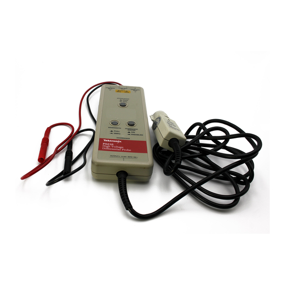
Getting Started This section describes the P5210 High Voltage Differential Probe and gives instructions on how to install and functionally test the probe. Features and Accessories The P5210 High Voltage Differential Probe shown in Figure 1 provides a safe means of measuring circuits with floating high voltages. - Seite 12 H The probe head and input cables are double insulated. H The control buttons and probe housing are non conductive and isolated. H The probe housing is internally shielded with a connection from the shield to earth ground through the output cable. P5210 Instructions...
- Seite 13 Getting Started Figure 1: P5210 High Voltage Differential Probe P5210 Instructions...
- Seite 14 WARNING. To avoid shock or burn hazard, use only the standard accessories or accessories that are rated for the application. Use the P5210 High Voltage Differential Probe accessories with this product only. Keep your fingers behind the finger guard on the probe body whenever possible to reduce the risk of a shock from the circuit under test.
- Seite 15 If your oscilloscope does not support the TEKPROBE interface, you can use the optional 1103 probe power supply as an effective interface. Contact your local Tektronix representative for more information. P5210 Instructions...
- Seite 16 The body is rated for the maximum input voltage of the P5210 High Voltage Differential Probe. The probe tip is a 6- - 32 threaded post that accepts the hook tips provided with the probe.
- Seite 17 The hook tip is rated for the maximum input voltage of the P5210 High Voltage Differential Probe. Install the large hook tip by sliding it over the body of the probe and screwing it onto the threaded probe tip.
- Seite 18 To use the marker bands, attach one band near the probe head and the matching band near the compensa- tion box. For a complete list of replaceable accessories and part ordering information, refer to the service manual that accompanies this product. P5210 Instructions...
-
Seite 19: Installation
Getting Started Installation Install the P5210 High Voltage Differential Probe as follows: 1. Connect the output of the probe to the TEKPROBE input of the oscilloscope or other measurement instrument. Make sure the measurement instrument is properly grounded. NOTE. Use the 1103 TEKPROBE Power supply if the instrument does not have the TEKPROBE interface. -
Seite 20: Functional Check
Getting Started Functional Check To make a simple functional check of the P5210 High Voltage Differential Probe, select a source that supplies AC line voltage and use the following procedure. This procedure verifies a majority of the circuitry within the probe. (For a complete performance verification, refer to the service manual that accompanies this product.) -
Seite 21: Operating Basics
Operating Basics To help you use the P5210 High Voltage Differential Probe safely and effectively, this section provides important information about safety limits, operating characteristics, and probing techniques. Operating the Probe Safely Before connecting the inputs of the probe to a circuit, read the safety information in this section and attach the appropriate accessories to the input connectors of the probe. -
Seite 22: Maximum Input Limits
RMS voltage.) You must also observe the ratings between the differential inputs and between each input and earth ground. CAUTION. To avoid damaging the input circuitry of the P5210, do not apply voltage of more than 2,200 V CAT II between either input... - Seite 23 4000 V 1000 V 500 V Voltage (RMS) 100 V 50 V DC or 0 100 k 500 k 10 M 50 M Frequency (Hz) Figure 2: Safety limits (voltage between either input and earth ground P5210 Instructions...
-
Seite 24: Operating Characteristics And Probing Techniques
Operating Basics Operating Characteristics and Probing Techniques This section explains the operating characteristics of the P5210 High Voltage Differential Probe along with techniques you can use to maximize the performance of the probe. Operating Limits The P5210 High Voltage Differential Probe has two operating ranges that you select with the ATTENUATION button on the front panel: 1,000X and 100X. -
Seite 25: Common-Mode Rejection
Common-Mode Rejection The common-mode rejection ratio (CMRR) is the specified ability of P5210 High Voltage Differential Probe to reject signals that are common to both inputs. More precisely, CMRR is the ratio of the differential gain to the common-mode gain. The higher the ratio, the greater the ability of probe to reject common-mode signals. -
Seite 26: Twisting The Input Leads
Frequency and impedance of the source determine how much the probe loads the circuit you are measuring. As the frequency of the source starts to increase beyond 1 kHz, the input impedance of the probe begins to decrease. P5210 Instructions... -
Seite 27: Cleaning
CAUTION. To avoid damaging the probe, use only a mild detergent and water solution or isopropyl alcohol. Do not use any other solvents or abrasive cleaners. Do not immerse the probe. P5210 Instructions... - Seite 28 Operating Basics P5210 Instructions...
-
Seite 29: Specifications
Specifications The specifications in Tables 2 through 6 apply to a P5210 High Voltage Differential Probe installed on a Tektronix TDS460A oscilloscope. When the probe is used with another oscilloscope, the oscilloscope must have an input impedance of 1 M Ω , an input capacitance range of between 15 and 20 pF, and a bandwidth greater than 200 MHz. -
Seite 30: Warranted Characteristics
Warranted characteristics that have checks in the Perfor- mance Verification procedure appear in boldface type. The Performance Verification procedure appears in the P5210 Service Manual (Tektronix part number 070-9895-XX, English only). P5210 Instructions... - Seite 31 Nonoperating: <85% RH at or below +60_ C The rating for DC voltage is the same as the rating for RMS voltage. The input voltage must not exceed this peak rating or the RMS rating. Tektronix Design Standard 062-2847-00 P5210 Instructions...
- Seite 32 UL3111-1 -- Standard for electrical measuring and test equipment IEC 10106-2-031 -- Particular requirements for hand-held probe assemblies for electrical measurement and test CAN/CSA-C22.2 No. 1010.1-92 and CAN/CSA-C22.2 No. 1010.2.031-94 -- Safety requirements for electrical equipment for measurement, control, and laboratory use P5210 Instructions...
- Seite 33 Equipment is usually cord-connected CAT I Secondary (signal level) or battery operated circuits of electronic equipment Pollution Degree 2 Do not operate in environments where conductive pollutants may be present. P5210 Instructions...
-
Seite 34: Typical Characteristics
See Figure 5 on page 27. Propagation Delay 20 nS Overdrive Recovery < 50 ns to 10% of final value after 10X overdrive (100X range only) 100X: ± 1.0 V DC Offset Adjust 1,000X: ± 10 V (referenced to input) P5210 Instructions... - Seite 35 (7.2 in × 2.6 in × 1.3 in) Dimensions, Input Leads 45.7 cm (18 in) Dimensions, Output Cable 1.8 m (6 ft) Unit Weight (probe only) 315 g (11 oz) Shipping Weight (with accessories) 1.42 kg (3 lb, 2 oz) P5210 Instructions...
- Seite 36 Specifications 40 dB 50 dB 60 dB 70 dB 80 dB 90 dB 1 Hz 10 Hz 100 Hz 1 kHz 10 kHz 100 kHz 1 MHz Frequency Figure 4: Typical Common-Mode Rejection Ratio (100X Attenuation) P5210 Instructions...
- Seite 37 Specifications 10 M 100 k 10 k 10 k 100 k 10 M 50 M Frequency (Hz) Figure 5: Input Impedance vs. Frequency P5210 Instructions...
-
Seite 38: Nominal Characteristics
Single-ended. Source Impedance of 50 Ω Output Type drives 1 MΩ oscilloscope input. Load impedance must be greater than 50 kΩ for stated accuracy Gain Switchable: 1/100 (100X) and 1/1,000 (1000X) Overrange Beeper Overrange sounds whenever ON, and over range LED is lit. P5210 Instructions... - Seite 39 Instructions Sonde différentielle haute tension P5210 070-9841-01 2 de 4 www.tektronix.com *P070984101* 070984101...
- Seite 40 Copyright © Tektronix, Inc. Tous droits réservés. Les produits Tektronix sont protégés par des brevets américains et étrangers déjà déposés ou en cours d’obtention. Les informations contenues dans ce document remplacent celles publiées précédemment. Les spécifications et les prix peuvent être modifiés.
- Seite 41 Tektronix, avec les frais d’expédition prépayés et une copie du certificat d’achat du client. Tektronix prendra à sa charge la réexpédition du produit au client si le destinataire se trouve dans le pays où le centre de réparation Tektronix est implanté. Tous les frais d’expédition, droits, taxes et autres frais afférents à...
- Seite 43 ......Caractéristiques nominales ......Instructions pour la sonde P5210...
-
Seite 44: Coordonnées De Tektronix
En dehors des heures de bureau, veuillez laisser un message sur le répondeur. Hors d’Amérique du Nord, adressez-vous à un bureau commercial Tektronix ou à un distributeur ; pour la liste des points de vente, consultez le site web Tektronix. Instructions pour la sonde P5210... -
Seite 45: Consignes Générales De Sécurité
Seul le personnel qualifié doit être autorisé à effectuer les opérations d’entretien. Respectez les tensions maximum d’utilisation N’utilisez pas la sonde différentielle haute tension P5210 avec des tensions supérieures à 1 000 V CAT II à la masse sur l’une des entrées ou ±... - Seite 46 état de ce matériel, faites-le inspecter par un technicien qualifié. N’utilisez pas ce matériel dans un environnement humide. N’utilisez pas ce matériel dans un environnement explosif. Maintenez les surfaces du produit propres et sèches. Instructions pour la sonde P5210...
- Seite 47 Symboles figurant sur le produit. Les symboles suivants peuvent figurer sur le produit : MISE EN GARDE AVERTISSEMENT Terminaison à la Dispose d’une Reportez-vous au Haute tension terre double isolation manuel Instructions pour la sonde P5210...
- Seite 48 Consignes générales de sécurité Instructions pour la sonde P5210...
-
Seite 49: Démarrage
Fonctions et accessoires La sonde différentielle haute tension P5210 représentée à la figure 1 fournit un moyen sûr pour mesurer les circuits présentant des hautes tensions fluctuantes. Elle délivre un signal de masse basse tension qui s’affiche sur les instruments dotés d’une interface TEKPROBE... - Seite 50 H Les boutons de commande et le boîtier de la sonde ne sont pas conducteurs et sont isolés. H L’intérieur du boîtier de la sonde est blindé et le blindage est relié à la terre via le câble de sortie. Instructions pour la sonde P5210...
- Seite 51 Démarrage Figure 1 : Sonde différentielle haute tension P5210 Instructions pour la sonde P5210...
- Seite 52 à l’application. Les accessoires de la sonde différentielle haute tension P5210 ne doivent être employés qu’avec ce produit. Placez les doigts derrière la protection sur le boîtier de la sonde chaque fois que cela est possible afin de réduire les risques de chocs provoqués par un circuit testé.
- Seite 53 Si votre oscilloscope ne prend pas en charge l’interface TEKPROBE, vous pouvez utiliser à défaut l’alimentation 1103 pour sonde en option. Pour plus d’informations, adressez-vous à votre représentant local Tektronix. Instructions pour la sonde P5210...
- Seite 54 Le corps est conçu en fonction de la tension d’entrée maximum de la sonde différentielle haute tension P5210. L’extrémité de la sonde est une tige filetée 6- - 32 sur laquelle se montent les embouts livrés avec la sonde.
- Seite 55 L’embout est conçu en fonction de la tension d’entrée maximum de la sonde différentielle haute tension P5210. Installez le grand embout en le faisant coulisser sur le corps de la sonde et en le vissant sur la tige filetée. Instructions pour la sonde P5210...
- Seite 56 Pour obtenir une liste complète des accessoires et des pièces de rechange et connaître les modalités de commande, reportez-vous au manuel d’entretien livré avec le produit. Instructions pour la sonde P5210...
-
Seite 57: Installation
Démarrage Installation Installez la sonde différentielle haute tension P5210 en procédant comme suit : 1. Raccordez la sortie de la sonde à la prise d’entrée TEKPROBE de l’oscilloscope ou d’un autre instrument de mesure. Vérifiez que l’instrument de mesure est correctement relié à la terre. -
Seite 58: Vérification De Fonctionnement
Vérification de fonctionnement Pour tester de manière très simple le bon fonctionnement de la sonde différentielle haute tension P5210, sélectionnez une source de courant alternatif et procédez comme suit : cette procédure permet de vérifier la plupart des circuits de la sonde. (Pour une vérification exhaustive des performances, reportez-vous au manuel d’entretien... -
Seite 59: Principes De Fonctionnement
à respecter, les caractéristiques et les techniques d’utilisation afin d’optimiser le maniement de la sonde différentielle haute tension P5210 en toute sécurité. Utilisation de la sonde en toute sécurité Avant de raccorder les entrées de la sonde à un circuit, lisez attentivement les consignes de sécurité... -
Seite 60: Limites Maximum D'entrée
(c.c. + crête c.a.) entre les entrées. Au-delà de 1,5 MHz, la limite de tension baisse, car la fréquence augmente. Voir la figure 2. La limite de puissance s’applique aux deux réglages, 100 X et 1 000 X. Instructions pour la sonde P5210... - Seite 61 1000 V 500 V Tension (efficace) 100 V 50 V DC ou 0 100 k 500 k 10 M 50 M Fréquence (Hz) Figure 2 : Limites de sécurité (tension entre l’entrée et la terre) Instructions pour la sonde P5210...
-
Seite 62: Caractéristiques De Fonctionnement Et Techniques D'utilisation
Caractéristiques de fonctionnement et techniques d’utilisation Cette section explique les caractéristiques de la sonde différentielle haute tension P5210 ainsi que les techniques pouvant être utilisées pour optimiser ses performances. Limites de fonctionnement La sonde différentielle haute tension P5210 dispose de deux plages d’utilisation que vous pouvez sélectionner à... -
Seite 63: Réjection En Mode Commun
60 Hz et de 500 V les deux cordons d’entrée de la sonde, cette dernière rejette le signal de 80 dB (type) et sur l’écran de l’oscilloscope, on peut lire un signal de seulement 50 mV Instructions pour la sonde P5210... -
Seite 64: Torsion Des Cordons D'entrée
La fréquence et l’impédance de la source désignent la charge induite par la sonde dans le circuit mesuré. Comme la fréquence de la source commence à augmenter au-delà de 1 kHz, l’impédance d’entrée de la sonde commence à baisser. Instructions pour la sonde P5210... -
Seite 65: Nettoyage
à base d’eau et de détergent doux ou d’isopropanol et d’eau. MISE EN GARDE. Pour éviter d’endommager la sonde, utilisez uniquement une solution à base d’eau et de détergent doux ou d’isopropanol. N’employez pas d’autres solvants ou détergents agressifs. N’immergez pas la sonde. Instructions pour la sonde P5210... - Seite 66 Principes de fonctionnement Instructions pour la sonde P5210...
-
Seite 67: Spécifications
Spécifications Les spécifications contenues dans les tableaux 2 à 6 s’appliquent à une sonde différentielle haute tension P5210 installée sur un oscilloscope Tektronix TDS460A. Lorsque la sonde est utilisée avec un autre oscilloscope, ce dernier doit avoir une impédance d’entrée de 1 M Ω... -
Seite 68: Caractéristiques Garanties
Les caractéristiques garanties cochées dans la procédure Vérification des performances sont en gras. La procédure de Vérification des performances figure dans le manuel d’entretien P5210 (référence Tektronix 070- - 9895- - XX, en anglais uniquement). Instructions pour la sonde P5210... - Seite 69 à +60_ C La valeur pour la tension C.C. est identique à celle pour la tension efficace. La tension d’entrée ne doit pas excéder cette valeur de crête ou la valeur efficace. Norme de conception Tektronix 062-2847-00 Instructions pour la sonde P5210...
- Seite 70 IEC 10106-2-031 -- Normes spéciales pour les sondes manuelles de mesure et de test électrique CAN/CSA-C22.2 No. 1010.1-92 et CAN/CSA-C22.2 No. 1010.2.031-94 -- Normes de sécurité pour les équipements électriques de mesure, de contrôle et de laboratoire Instructions pour la sonde P5210...
- Seite 71 à un cordon d’alimentation. CAT I Circuits secondaires (niveau de signal) ou alimentés par batterie sur les équipements électroniques. Niveau de pollution 2 N’utilisez pas ce matériel dans des environnements susceptibles d’abriter des polluants conducteurs. Instructions pour la sonde P5210...
-
Seite 72: Caractéristiques Types
< 50 ns à 10 % de la valeur finale après une surcharge de 10 X (plage 100 X uniquement) 100X : ± 1,0 V Ajustement du décalage en continu 1 000X : ± 10 V (par rapport à l’entrée) Instructions pour la sonde P5210... - Seite 73 185 mm × 66 mm × 32 mm Dimensions, boîtier Dimensions, cordons d’entrée 45,7 cm Dimensions, câble de sortie 1,8 m Poids de l’unité (sonde uniquement) 315 g Poids d’expédition (avec les accessoires) 1,42 kg Instructions pour la sonde P5210...
- Seite 74 60 dB 70 dB 80 dB 90 dB 1 Hz 10 Hz 100 Hz 1 kHz 10 kHz 100 kHz 1 MHz Fréquence Figure 4 : Taux de réjection en mode commun type (atténuation 100 X) Instructions pour la sonde P5210...
- Seite 75 Spécifications 10 M 100 k 10 k 10 k 100 k 10 M 50 M Fréquence (Hz) Figure 5 : Impédance d’entrée / Fréquence Instructions pour la sonde P5210...
-
Seite 76: Caractéristiques Nominales
Gain Commutable : 1/100 (100X) et 1/1 000 (1 000X) Beeper de dépassement de plage Le beeper se déclenche quand il est activé et que le témoin de dépassement de plage s’allume. Instructions pour la sonde P5210... -
Seite 77: Anleitung
Anleitung P5210 Hochspannungs-Differentialtastkopf 070-9841-01 3 von 4 www.tektronix.com *P070984101* 070984101... - Seite 78 Auslandspatente geschützt. Die Informationen in dieser Broschüre machen Angaben in allen früheren Unterlagen hinfällig. Änderungen der Spezifikationen und der Preisgestaltung vorbehalten. Tektronix Inc., P.O. Box 500, Beaverton, OR 97077, USA TEKTRONIX, TEK und TEKPROBE sind eingetragene Warenzeichen von Tektronix Inc.
- Seite 79 Ersatz für dieses fehlerhafte Produkt zur Verfügung zu stellen. Batterien sind von dieser Garantie ausgeschlossen. Um mit dieser Garantie Kundendienst zu erhalten, muß der Kunde Tektronix über den Fehler vor Ablauf der Garantiezeit informieren und passende Vorkehrungen für die Durchführung des Kundendienstes treffen.
- Seite 81 ....... . Nominale Merkmale ....... P5210 Anleitung...
-
Seite 82: Tektronix-Kontaktinformationen
Diese Rufnummer ist in Nordamerika gebührenfrei. Außerhalb der Geschäftszeiten können Sie eine Nachricht auf dem Anrufbeantworter hinterlassen. Kunden außerhalb Nordamerikas wenden sich an eine Tektronix-Niederlassung oder einen Tektronix-Händler in der Nähe. Eine Liste unserer Verkaufsbüros finden Sie auf der Tektronix-Website. P5210 Anleitung... -
Seite 83: Allgemeine Sicherheitshinweise
Wartungsarbeiten sind nur von qualifiziertem Personal durchzuführen. Einhalten der maximalen Arbeitsspannung Die maximal zulässige Spannung an den Eingängen des P5210 Hochspannungs-Differentialtastkopfs beträgt in Kreisen der bezogen auf Masse bzw. ± 1300 V Kategorie II 1000 V zwischen den Anschlüssen (DC + AC-Scheitelwert). - Seite 84 Gerät beschädigt ist, lassen Sie es von qualifiziertem Wartungspersonal überprüfen. Betreiben Sie das Gerät nicht in feuchter oder nasser Umgebung. Betreiben Sie das Gerät nicht in explosiver Atmosphäre. Halten Sie die Oberfläche des Geräts sauber und trocken. P5210 Anleitung...
-
Seite 85: Sicherheitsrelevante Begriffe Und Symbole
Hinweisstelle in Verbindung steht. CAUTION weist auf mögliche Sach- oder Geräteschäden hin. Symbole am Gerät. Am Gerät sind eventuell die folgenden Symbole zu sehen: VORSICHT Doppelt WARNUNG Schutzleiteranschluß Beachten Sie die isoliert (Erde) Hochspannung Hinweise im Handbuch P5210 Anleitung... - Seite 86 Allgemeine Sicherheitshinweise P5210 Anleitung...
-
Seite 87: Erste Schritte
Messen in Schaltungen mit erdfreier Hochspannung. Am Tastkopfausgang liegt ein massebezogenes Niederspannungssignal an, das auf Meßgeräten mit TEKPROBE- Schnittstellen dargestellt werden kann. Wenn das Netzteil Tektronix TekProbe 1103 verwendet wird, läßt sich das Signal mit einem beliebigen Oszilloskop oder Meßgerät anzeigen. - Seite 88 Eingangsgrenzwert des Tastkopfs. H Der Tastkopf selbst und die Eingangskabel sind doppelt isoliert. H Die Bedientasten sowie das Tastkopfgehäuse sind isoliert und nicht leitend. H Das Tastkopfgehäuse ist innen abgeschirmt. Die Schirmung ist über das Ausgangskabel mit Erde verbunden. P5210 Anleitung...
- Seite 89 Erste Schritte Abbildung 1: P5210 Hochspannungs-Differentialtastkopf P5210 Anleitung...
- Seite 90 WARNUNG. Zum Schutz vor Stromschlägen und Verbrennungen darf nur das Standardzubehör oder solches Zubehör verwendet werden, das für die jeweilige Anwendung geeignete Kennwerte aufweist. Verwenden Sie mit diesem Gerät ausschließlich P5210 Hochspannungs-Differentialtastkopf-Zubehör. Halten Sie Ihre Finger möglichst immer hinter der Schutzmanschette.
- Seite 91 TEKPROBE-Schnittstelle. Die TEKPROBE-Schnittstelle stellt die Stromversorgung bereit und übernimmt die Datenübertragung des Signals sowie der Tastkopfcharakteristik. Unterstützt ein Oszilloskop die TEKPROBE- Schnittstelle nicht, kann das optionale Tastkopfnetzteil 1103 als Schnittstelle verwendet werden. Nähere Informationen erhalten Sie bei Ihrem lokalen Tektronix-Händler. P5210 Anleitung...
- Seite 92 Tastkopfgehäuse. Bei der Entwicklung des Tastkopfg- häuses standen Bedienersicherheit, ergonomische Handhabung und Signaldarstellgüte im Vordergrund. Gehäuse ist für die maximale Eingangsspannung des P5210 Hochspannungs-Differentialtastkopfs ausgelegt. Die Tastkopfspitze ist als Schaft mit Gewinde (6- - 32) ausgeführt, auf den die mitgelieferten Hakenspitzen Tastkopfspitze mit aufgesetzt werden können.
- Seite 93 Kleine Hakenspitze. Die kleine Hakenspitze ist für den Anschluß an kleine Leiter, wie etwa die Anschlußbeine von Bauteilen, vorgesehen. Die Hakenspitze ist für die maximale Eingangsspannung des P5210 Hochspannungs-Differentialtastkopfs ausgelegt. Schieben Sie die kleine Hakenspitze über das Tastkopfgehäuse, und schrauben Sie sie auf das Gewinde an der Tastkopfspitze.
- Seite 94 Bringen Sie jeweils einen Streifen in der Nähe der Tastkopfspitze und einen gleichfarbigen Streifen in der Nähe des Kompensationsmoduls an. Eine vollständige Liste der austauschbaren Zubehörteile finden Sie zusammen mit Bestellhinweisen im Wartungshandbuch, das mit dem Gerät geliefert wird. P5210 Anleitung...
-
Seite 95: Installation
Erste Schritte Installation Gehen Sie zur Installation des P5210 Hochspannungs-Differentialtastkopfs in folgenden Schritten vor: 1. Schließen Sie den Ausgang des Tastkopfs an den Eingang TEKPROBE des Oszilloskops bzw. eines anderen Meßgeräts an. Überprüfen Sie, ob das Meßgerät einwandfrei geerdet ist. -
Seite 96: Funktionsprüfung
Gerät geliefert wird.) 1. Führen Sie die Installationsschritte aus, die ab Seite 9 beschrieben sind, und schließen Sie den Ausgang des P5210 Hochspannungs-Differentialtastkopfs an ein Meßgerät an. 2. Schließen Sie die Eingänge an, stellen Sie den Bereich ein, und führen Sie die Prüfungen durch, die in den einzelnen Zeilen von... -
Seite 97: Bedienungsgrundlagen
Bedienungsgrundlagen Dieses Kapitel enthält Hinweise zum sicheren und effizienten Einsatz des P5210 Hochspannungs-Differentialtastkopfs. Sie finden wichtige Informationen zu Sicherheitsgrenzwerten, Bedienungsmerkmalen und Meßverfahren. Sicherer Umgang mit dem Tastkopf Bevor Sie die Tastkopfeingänge an einen Stromkreis anschließen, sollten Sie die Sicherheitshinweise in diesem Kapitel lesen und das geeignete Zubehör an den Eingangsanschlüssen des Tastkopfs... -
Seite 98: Eingangsgrenzwerte
Differenzeingängen bzw. zwischen einem Eingang und Erde nicht überschritten werden. VORSICHT. Zur Verhinderung von Schäden an der Eingangsschaltung des P5210 dürfen in Kreisen der Kategorie II zwischen einem Eingang und Erde keine Spannungen über 2200 V bzw. zwischen den beiden Eingängen keine Spannungen über 4400 V... - Seite 99 HF-Verbrennungen (grau) zunehmender Frequenz 4000 V 1000 V 500 V Spannung (eff) 100 V 50 V DC or 0 100 k 500 k 10 M 50 M Frequenz (Hz) Abbildung 2: Sicherheitsgrenzwerte (Spannung zwischen einem Eingang und Erde P5210 Anleitung...
-
Seite 100: Bedienungsmerkmale Und Meßverfahren
Bedienungsgrundlagen Bedienungsmerkmale und Meßverfahren Dieser Abschnitt beschreibt die Bedienungsmerkmale des P5210 Hochspannungs-Differentialtastkopfs sowie Verfahren, mit denen sich die Leistungsfähigkeit des Tastkopfs steigern läßt. Betriebsgrenzwerte Der P5210 Hochspannungs-Differentialtastkopf kann in zwei verschiedenen Dämpfungsstufen betrieben werden, die mit der Taste ATTENUATION an der Frontplatte ausgewählt werden: 100-fach und 1000-fach (Beschriftung 1,000 X bzw. -
Seite 101: Gleichtaktunterdrückung
Kategorie II können das Ausgangssignal verzerren. Allerdings signalisiert der Tastkopf in diesem Fall keine Bereichsüberschreitung. Gleichtaktunterdrückung Die Gleichtaktunterdrückung des P5210 Hochspannungs-Differentialtastkopfs bezeichnet die Fähigkeit, Signale zu sperren, die an beiden Eingängen gleichzeitig anliegen. Präzise ausgedrückt: Die Gleichtaktunterdrückung ist das Verhältnis von Differenzverstärkung zu Gleichtaktverstärkung. -
Seite 102: Verdrillen Der Eingangsleitungen
Der Tastkopf stellt für die Schaltung, an die er angeschlossen wird, eine zusätzliche ohmsche, kapazitive sowie induktive Last dar. Frequenz und Impedanz der Quelle bestimmen, wie stark der Tastkopf den Meßkreis belastet. Sobald die Quellenfrequenz den Wert von 1 kHz überschreitet, nimmt die Eingangsimpedanz des Tastkopfs ab. P5210 Anleitung... -
Seite 103: Reinigung
Reinigung Verwenden Sie zur Reinigung ein weiches Tuch, das mit einer milden Reinigungslösung oder mit wasserverdünntem Isopropylalkohol angefeuchtet wurde. VORSICHT. Scheuermittel sowie scharfe Reinigungs- und Lösungs-mittel können den Tastkopf beschädigen. Tauchen Sie den Tastkopf niemals in Flüssigkeit ein. P5210 Anleitung... - Seite 104 Bedienungsgrundlagen P5210 Anleitung...
-
Seite 105: Spezifikationen
Spezifikationen Die Spezifikationen in den Tabellen 2 bis 6 gelten für einen P5210 Hochspannungs-Differentialtastkopf, der an ein Oszilloskop des Typs Tektronix TDS460A angeschlossen ist. Wird ein anderes Oszilloskop verwendet, muß dieses die folgenden Kenndaten aufweisen: Ein- gangsimpedanz min. 1 MW, Eingangskapazitätsbereich zwischen 15 und 20 pF, Bandbreite größer 200 MHz. -
Seite 106: Garantierte Merkmale
Voraussetzungen garantiert werden. Garantierte Merkmale, die bei einer Prüfung der Leistungsmerkmale untersucht werden, sind in Fettschrift gedruckt. Die Vorgehensweise zur Prüfung der Leistungsmerkmale ist im Wartungshandbuch zum P5210 beschrieben (Tektronix-Teilenummer 070- - 9895- - XX, nur auf Englisch verfügbar). P5210 Anleitung... - Seite 107 Betrieb: <85 % rel. Luftfeuchtigkeit bei max. +35 _C Lagerung: <85 % rel. Luftfeuchtigkeit bei max. +60 _C Der Gleichspannungsgrenzwert ist mit dem Effektivspannungsgrenzwert identisch. Die Eingangsspannung darf diesen Spitzenwert und auch den Effektivspitzenwert nicht überschreiten. Tektronix-Konstruktionsstandard 062-2847-00 P5210 Anleitung...
- Seite 108 Zulassungen UL3111-1 -- Norm für elektrische Meß- und Prüfgeräte IEC 10106-2-031 -- Besondere Anforderungen an elektrische Meß- und Prüfgeräte mit Handprüfköpfen CAN/CSA-C22.2 Nr. 1010.1-92 und CAN/CSA-C22.2 Nr. 1010.2.031-94 -- Sicherheitsanforderungen für elektrische Geräte für Messungen, Steuerung und Laborzwecke P5210 Anleitung...
- Seite 109 Ebene umfassen Haushaltsgeräte, tragbare Werkzeuge und ähnliche Geräte. Solche Geräte sind normalerweise über ein Kabel angeschlossen CAT I Sekundäre (Signalebene) oder batteriebetriebene Schaltungen elektronischer Geräte Belastungsgrad 2 Das Gerät darf nicht in Umgebungen betrieben werden, in denen leitende Verunreinigungen vorhanden sind. P5210 Anleitung...
-
Seite 110: Typische Merkmale
8 MΩ, 7 pF zwischen Eingang und Masse siehe Abbildung 5 auf Seite 27. Laufzeitverzögerung 20 nS Übersteuerungs-Erholzeit < 50 ns bis 10 % des Endwerts nach 10-facher Übersteuerung (nur bei Dämpfung 100-fach) 100-fach: ± 1,0 V DC-Offsetkompensation 1000-fach: ± 10 V (bezogen auf Eingangssignal) P5210 Anleitung... - Seite 111 185 mm × 66 mm × 32 mm Abmessungen Tasche (7,2” × 2,6” × 1,3”) Abmessungen Eingangsleitungen 45,7 cm (18”) Abmessungen Ausgangskabel 1,8 m (6 ft) Gewicht (nur Tastkopf) 315 g (11 oz) Transportgewicht (mit Zubehör) 1,42 kg (3 lb, 2 oz) P5210 Anleitung...
- Seite 112 Spezifikationen 40 dB 50 dB 60 dB 70 dB 80 dB 90 dB 1 Hz 10 Hz 100 Hz 1 kHz 10 kHz 100 kHz 1 MHz Frequenz Abbildung 4: Typisches Gleichtaktunterdrückungsverhältnis (100-fache Dämpfung) P5210 Anleitung...
- Seite 113 Spezifikationen 10 M 100 k 10 k 10 k 100 k 10 M 50 M Frequenz (Hz) Abbildung 5: Eingangsimpedanz in Abhängigkeit von der Frequenz P5210 Anleitung...
-
Seite 114: Nominale Merkmale
50 Ω zur Ansteuerung eines Oszilloskopeingangs mit 1 MΩ. Damit die angegebene Messgenauigkeit erreicht wird, muß die Lastimpedanz größer als 50 kΩ sein Verstärkung Schaltbar: 1/100 (Dämpfung 100-fach) oder 1/1000 (Dämpfung 1000-fach) Bereichsüberschreitungssummer Tastenstellung ON: Akustische Bereichsüberschreitungsmeldung in Verbindung mit LED-Anzeige. P5210 Anleitung... - Seite 115 インストラクション・マニュアル P5210型 高電圧差動プローブ 070-9841-01 4 o f 4 w w w . t e k t r o n i x . c o m *P070984101* 0 7 0 9 8 4 1 0 1...
- Seite 116 Copyright © Tektronix, Inc. All rights reserved. Tektronix products are covered by U.S. and foreign patents, issued and pending. Information in this publication supercedes that in all previously published material. Specifications and price change privileges reserved. Tektronix, Inc., P.O. Box 500, Beaverton, OR 97070 TEKTRONIX, TEK and TEKPROBE are registered trademarks of Tektronix, Inc.
- Seite 117 ..............
- Seite 118 P5210 1,000V CAT II 1,300V(DC + peak AC) RF Radio Frequency P5210...
- Seite 120 DANGER WARNING CAUTION P5210...
- Seite 121 P5210 P5210 TEKPROBE 1103 P5210...
- Seite 122 P5210...
- Seite 123 1: P5210...
- Seite 124 2,200V CATII 4,400V 5,600V (DC+peak AC) 1000 1000 4,400V CAT II 100 440V CAT II OVERRANGE P5210...
- Seite 125 FULL 50MHz 5MHz TEKPROBE TEKPROBE 1103...
- Seite 126 P5210 6 32 P5210...
- Seite 127 P5210 P5210...
- Seite 128 P5210...
- Seite 129 P5210 TEKPROBE TEKPROBE 1103 2. 440V ATTENUATION OVERRANGE 1000 a. TEKPROBE TEKPROBE 1103 1000 c. 2...
- Seite 130 P5210 1. 9 P5210 (- or +) (+ or -) 1,000 1,000 P5210...
- Seite 131 P5210 RF Radio Frequency...
- Seite 132 P5210 2,200V CAT II 2 4,400V 5,600V (DC+peakAC) 1.5MHz 1000 P5210...
- Seite 133 2,200V 4000V 1000V 500V 100V DC(0) 100k 500k...
- Seite 134 P5210 P5210 ATTENUATION H 100 560V (DC+peakAC) H 1000 5,600V (DC+peakAC) 2,200V 4,400V OVERRANGE OVER RANGE BEEPER P5210...
-
Seite 135: Common Mode Rejection
2,200V CAT II OVERRANGE Common Mode Rejection P5210 CMRR:Common-Mode Rejec tion Ratio CMRR CMRR CMRR 60Hz 500V 80dB 50mV... - Seite 136 1kHz P5210...
- Seite 138 P5210...
- Seite 139 P5210 TDS460A TDS460A 15 20pF 200MHz...
- Seite 140 : 070 9895 XX P5210...
- Seite 141 3000:1 CMRR 500VDC +20 50 MHz(-3dB) 3% +20 4.4 kV , CAT I&II 1 kV 1 kV , CAT III , CAT III 5.6 kV (DC+peakAC) 2.2 kV , CAT I&II 1 kV , CAT III Tektronix 062 2847 00...
- Seite 142 IEC 10106 2 031: Particular requirements for hand held probe assemblies for elec trical measurement and test CAN/CSA C22.2 No. 1010.1 92 and CAN/CSA C22.2 No. 1010.2.031 94: Safety requirements for electrical equipment for measurement, control, and laboratory use P5210...
- Seite 143 (Cont.) CAT III CAT II CAT I...
- Seite 144 100 kHz: 300:1 1 MHz: 300:1 100 : 150 mV (referenced to input) 1,000 : 800 mV 16 MW, 3.5 pF 8 MW, 7 pF 20 nS 50ns 100 : + 1.0 V (referenced to input) 1,000 : + 10 V P5210...
- Seite 145 185 mm 66 mm 32 mm 45.7 cm 1.8 m 315 g 1.42 kg...
- Seite 146 40 dB 50 dB 60 dB 70 dB 80 dB 90 dB 1 Hz 10 Hz 100 Hz 1 kHz 10 kHz 100 kHz 1 MHz 4: CMRR P5210...
- Seite 147 10 M 100 k 10 k 10 k 100 k 10 M 50 M...
- Seite 148 Balanced differential 50 W 50kW 1/100 100 1/1,000 1000 OVERRANGE OVER RANGE BEEPER ON P5210...
- Seite 149 Tektronix, shipping charges prepaid, and with a copy of customer proof of purchase. Tektronix shall pay for the return of the product to Customer if the shipment is to a location within the country in which the Tektronix service center is located.
- Seite 151 (This warranty is valid only in Japan.)
- Seite 152 TEL 03 3448 3010 FAX 0120 046 011 5 9 31 141 0001 9:00 12:00 13:00 17:00 E-Mail: ccc@sonytek.co.jp URL: http://www.sonytek.co.jp TEL 0120 741 046 FAX 0550 89 8268 143-1 412 0047 9:00 12:00 13:00 19:00...