Fronius OPT/i Bedienungsanleitung
Vorschau ausblenden
Andere Handbücher für OPT/i:
- Installationsanleitung (36 Seiten) ,
- Installationsanleitung (12 Seiten)

Verwandte Anleitungen für Fronius OPT/i


Inhaltszusammenfassung für Fronius OPT/i
- Seite 1 Operating Instructions OPT/i externer Gasregler OPT/i external gas regulator Bedienungsanleitung EN-US Operating instructions 42,0410,2665 004-31012025...
-
Seite 3: Inhaltsverzeichnis
Lieferumfang Einbau vor Ort Gasregler Lieferumfang Einbau vor Ort Plasmagas Anschlüsse und mechanische Komponenten Anschlüsse und mechanische Komponenten Installation Sicherheit Erforderliches Werkzeug Vorbereitung OPT/i TIG Gasregler einbauen OPT/i TIG Plasmagasregler einbauen Zweiten Gasregler einbauen Abschließende Tätigkeiten Inbetriebnahme Sicherheit Zusätzlich erforderlich Verbindung zum Schweißsystem herstellen Voraussetzungen für den Betrieb... -
Seite 4: Allgemeines
Allgemeines Funktionsprinzip Der externe Gasregler misst und regelt die erforderliche Gasmenge. Für alle Schweißprozesse ist damit ein ausreichender Gasschutz gegeben. Der externe Gasregler verfügt über einen Gassensor und ein Regelventil. Das Schweißgerät wertet das Mess-Signal des Gassensors kontinuierlich aus und sorgt für eine entsprechende Ansteuerung des Regelventils. -
Seite 5: Korrekturfaktor Für Verwendete Schutzgase
Schutzgas ab. Für nicht vorprogrammierte Schutzgase gibt es Korrekturfaktoren für den Regelungs-Abgleich. Somit kann für alle Materialar- ten die ausgewählt werden können, die gewünschte Schutzgasmenge exakt ein- gehalten werden. Optionen OPT/i TIG Gasregler 4,101,259 OPT/i TIG Formiergasregler 4,101,315 OPT/i TIG Schleppgasregler... -
Seite 6: Lieferumfang Einbau Vor Ort Gasregler
Die optionalen zweiten Gasregler für Formiergas oder Schleppgas sind mit je 2 Stk. Schraube M3x40 und für Plasmagas mit 2 Stk. M3x50 Schraube ausgestattet. Regelventil Gassensor-Kabel Gassensor externer Gasanschluss-Schlauch 1,5 m (nicht bei 4,101,259 OPT/i TIG Gasregler) 2 Stk. Gasschlauch (16 cm) -
Seite 7: Lieferumfang Einbau Vor Ort Plasmagas
Lieferumfang Gilt für: Einbau vor Ort OPT/i TIG Plasmagasregler Plasmagas Gasanschluss mit Flachmutter Steckkupplung 2 Stk. Winkel-Steckanschluss 2 Stk. Schraube M3x50 Regelventil Gassensor-Kabel Gassensor Montagewinkel 4 Stk. Furchschraube KST 3x12 DeltaPT (10) externer Gasanschluss-Schlauch 1,5 m (11) 2 Stk. Gasschlauch (16 cm) -
Seite 8: Anschlüsse Und Mechanische Komponenten
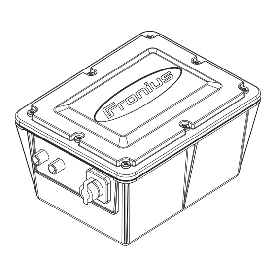
Anschlüsse und mechanische Komponenten Anschlüsse und mechanische Komponenten Deckel Anschluss GAS 2 IN Anschluss GAS 1 IN Anschluss SpeedNet Blindabdeckung Anschluss GAS 1 OUT Anschluss GAS 2 OUT... -
Seite 9: Installation
Gefahr durch Fehlbedienung und fehlerhaft durchgeführte Arbeiten. Schwere Personen- und Sachschäden können die Folge sein. ▶ Alle in diesem Dokument beschriebenen Arbeiten und Funktionen dürfen nur von Fronius-geschultem Servicepersonal ausgeführt werden. ▶ Dieses Dokument vollständig lesen und verstehen. ▶ Sämtliche Sicherheitsvorschriften und Benutzerdokumentationen dieses Gerätes und aller Systemkomponenten lesen und verstehen. -
Seite 10: Vorbereitung
Vorbereitung WARNUNG! Gefahr durch elektrischen Strom. Schwere Personen- und Sachschäden können die Folge sein. ▶ Vor Beginn der Arbeiten alle beteiligten Geräte und Komponenten aus- schalten und vom Stromnetz trennen. ▶ Alle beteiligten Geräte und Komponenten gegen Wiedereinschalten si- chern. ▶... - Seite 11 Folie an Position GAS 1 OUT aus- schneiden. Mit einem Bohrer Ø 14 mm eine Bohrung anbringen. Kabel Y1:A1 und Y1:A2 gemäß Ka- belaufdruck am Regelventil anste- cken. Regelventil von innen nach außen in die Bohrung bei GAS 1 IN ein- setzen.
-
Seite 12: Opt/I Tig Gasregler Einbauen
OPT/i TIG Gas- Gassensor-Kabel am Gassensor regler einbauen anstecken. WICHTIG! Auf Einbaurichtung achten. Gassensor am Halteblech montie- ren. 2 Stk. Winkel-Steckanschlüsse am Gassensor anstecken. - Seite 13 WICHTIG! Beim Anstecken des Gassensor-Kabels darauf achten, dass die Verriegelung des Steckers in Richtung Printkante zeigt. Gassensor-Kabel am Print an „X5 SENSOR 1“ anstecken. Gasschlauch am Regelventil anste- cken. Gasschlauch am Gassensor anste- cken. Steckkupplung am Gasanschluss anstecken. Zweiten Gasschlauch am Gasan- schluss anstecken.
-
Seite 14: Opt/I Tig Plasmagasregler Einbauen
OPT/i TIG Plas- Gassensor-Kabel am Gassensor magasregler ein- anstecken. bauen Montagewinkel am Gassensor be- festigen. WICHTIG! Auf Einbaurichtung achten. Gassensor am Halteblech montie- ren. - Seite 15 2 Stk. Winkel-Steckanschlüsse am Gassensor anstecken. WICHTIG! Beim Anstecken des Gassensor-Kabels darauf achten, dass die Verriegelung des Steckers in Richtung Printkante zeigt. Gassensor-Kabel am Print an „X5 SENSOR 1“ anstecken. Gasschlauch am Regelventil anste- cken. Gasschlauch am Gassensor anste- cken. Steckkupplung am Gasanschluss anstecken.
-
Seite 16: Zweiten Gasregler Einbauen
Zweiten Gasschlauch am Gasan- schluss anstecken. Zweiten Gasschlauch am Gassen- sor anstecken. Zweiten Gasreg- Voraussetzung: ler einbauen In der Gasregler-Box ist ein Gasregler eingebaut. GAS 1 IN und GAS 1 OUT sind belegt. Folie an den Positionen GAS 2 IN und GAS 2 OUT ausschneiden. Mit einem Stufenbohrer Ø... -
Seite 17: Abschließende Tätigkeiten
Zweiten Gassensor und den vor- handenen Gassensor mit den Schrauben und Unterlegscheiben aus dem Lieferumfang montieren. WICHTIG! Beim Anstecken des zweiten Gassensor-Kabels darauf achten, dass die Verriegelung des Steckers in Richtung Printkante zeigt. 2 Stk. Winkel-Steckanschlüsse am zweiten Gassensor anstecken. Zweites Gassensor-Kabel am Print an „X4 SENSOR 2“... -
Seite 18: Inbetriebnahme
SpeedNet-Kabel derlich Verbindung zum Den externen Gasregler an einer geeigneten Position platzieren. Zum Beispiel Schweißsystem mit der OPT/i Mounting Gasregler am Fahrwagen. Siehe Installationsanlei- herstellen tung OPT/i Mounting Gasregler. Den Gasregler mit einem SpeedNet-Kabel (nicht im Lieferumfang enthalten) am SpeedNet-Anschluss des Schweißgeräts oder des Drahtvorschubs an- schließen. -
Seite 19: Inbetriebnahme Plasmagas
Inbetriebnahme Schweißsystem an das Stromnetz anschließen. Plasmagas Netzschalter des Schweißgeräts in Stellung - I - schalten. Am Schweißgerät unter Prozessparameter > Allgemein WIG/MMA/Plasma > [nächste Seite]> Plasma > den jeweiligen Plasmagas-Sollwert und den Korrekturfaktor (Plasmagasfaktor am Schweißgerät) einstellen. Maximale Gas- Die maximale Gas-Durchflussmenge des Gassensors errechnet sich wie folgt: Durchflussmen- Maximale Gas-Durchflussmenge (l/min) = 30 x Korrekturfaktor... -
Seite 20: Korrekturfaktoren Der Gängigsten Schutzgase
1,00 Luft 100 % Luft 1,53 HINWEIS! Der Korrekturfaktor 1,72 bei Argon gilt auch für den OPT/i TIG Plasmagas- regler. Alle anderen Korrekturfaktoren sind für den OPT/i TIG Plasmagasreg- ler nicht oder nur bedingt anwendbar. Ar-He Schutzgas-Gemische Haupt- und Un-... - Seite 21 Haupt- und Un- tergruppe nach % CO EN ISO 14175 % Ar Ar + 30 % He + 0,5 % 69,50 0,50 2,30 Ar + 30 % He + 2 % CO 2,27 Ar + 30 % He + 67,50 2,50 2,26 2,5 % CO...
- Seite 22 Haupt- und Un- tergruppe nach % CO EN ISO 14175 % Ar Ar + 9 % CO 1,62 Ar + 8‑10 % CO Ar + 10 % CO 1,60 Ar + 12 % CO 1,58 Ar + 15 % CO 1,55 Ar + 15-20 % CO 1,52...
-
Seite 23: Technische Daten
Technische Daten OPT/i Externer OPT/i TIG Gasregler, OPT/i TIG Formiergasregler, OPT/i TIG Schleppgasregler Gasregler Regelbereich 0,5 - 30 l/min (1,07 - 64,29 cfh) Versorgungsspannung 24 V Maximaler Eingangsdruck 7 bar (101.49 psi) Toleranz +/- 10 % vom Endwert (max.) Linearität +/- 5 % vom Messwert (max.) - Seite 25 Scope of delivery—installation on-site Plasma gas Connections and mechanical components Connections and mechanical components Installation Safety Required tools Preparation Installing the OPT/i TIG gas regulator Installing OPT/i TIG plasma gas regulator Installing the second gas regulator Final tasks Commissioning Safety Additionally required...
-
Seite 26: General
General Operating The external gas regulator measures and controls the required amount of gas. principle This provides an adequate gas shield for all welding processes. The external gas regulator has a gas sensor and a control valve. The welding ma- chine continuously evaluates the measuring signal from the gas sensor and ensu- res appropriate control of the control valve. -
Seite 27: Correction Factor For Shielding Gases Used
Options OPT/i TIG gas regulator 4,101,259 OPT/i TIG forming gas regulator 4,101,315 OPT/i TIG trailing gas regulator 4,101,316 OPT/i TIG plasma gas regulator 4,101,314... -
Seite 28: Scope Of Delivery-Installation On-Site Gas Regulator
2 M3x40 screws each, and for plasma gas with 2 M3x50 screws. Control valve Gas sensor cable Gas sensor External shielding gas connection hose 1.5 m (not with 4,101,259 OPT/i TIG gas regulator) 2 gas hoses (16 cm) -
Seite 29: Scope Of Delivery-Installation On-Site Plasma Gas
Scope of deli- Applies to: very—installati- OPT/i TIG plasma gas regulator on on-site Plasma gas Shielding gas connection with flat nut Plug-in coupling 2 angled connections 2 M3x50 screws Control valve Gas sensor cable Gas sensor Mounting bracket 4 KST 3x12 DeltaPT self-tapping screws (10) External shielding gas connection hose 1.5 m... -
Seite 30: Connections And Mechanical Components
Connections and mechanical components Connections and mechanical com- ponents Connection GAS 2 IN Connection GAS 1 IN SpeedNet connection Dummy cover Connection GAS 1 OUT Connection GAS 2 OUT... -
Seite 31: Installation
This can result in serious personal injury and damage to property. ▶ All the work and functions described in this document must only be carri- ed out by a trained Fronius service technician. ▶ Read and understand this document in full. -
Seite 32: Preparation
Preparation WARNING! Danger from electrical current. This can result in serious personal injury and damage to property. ▶ Before starting work, switch off all the devices and components involved and disconnect them from the grid. ▶ Secure all devices and components involved so they cannot be switched back on. - Seite 33 Cut film at position GAS 1 OUT. Drill a bore with a Ø 14 mm drill. Connect cable Y1:A1 and Y1:A2 to the control valve as per the lette- ring on the cable. Insert the control valve from insi- de to outside into the bore at GAS 1 IN.
-
Seite 34: Installing The Opt/I Tig Gas Regulator
Installing the Connect the gas sensor cable to OPT/i TIG gas the gas sensor. regulator IMPORTANT! Pay attention to the direction of instal- lation. Mount the gas sensor on the retai- ning plate. Connect 2 angled connections to the gas sensor. - Seite 35 IMPORTANT! When plugging in the gas sensor cable, ensure that the plug locking mecha- nism points in the direction of the PC board edge. Connect the gas sensor cable to the PC board at "X5 SENSOR 1". Connect the gas hose to the con- trol valve.
-
Seite 36: Installing Opt/I Tig Plasma Gas Regulator
Installing OPT/i Connect the gas sensor cable to TIG plasma gas the gas sensor. regulator Attach the mounting bracket to the gas sensor. IMPORTANT! Pay attention to the direction of instal- lation. Mount the gas sensor on the retai- ning plate. - Seite 37 Connect 2 angled connections to the gas sensor. IMPORTANT! When plugging in the gas sensor cable, ensure that the plug locking mecha- nism points in the direction of the PC board edge. Connect the gas sensor cable to the PC board at "X5 SENSOR 1". Connect the gas hose to the con- trol valve.
-
Seite 38: Installing The Second Gas Regulator
Plug the second gas hose into the shielding gas connection. Connect the second gas hose to the gas sensor. Installing the se- Requirement: cond gas regula- The gas regulator box has a built-in gas regulator. GAS 1 IN and GAS 1 OUT are occupied. Cut out the film at the positions GAS 2 IN and GAS 2 OUT. -
Seite 39: Final Tasks
Fit the second gas sensor and the existing gas sensor using the screws and washers included in the scope of delivery. IMPORTANT! When plugging in the second gas sensor cable, ensure that the plug locking mechanism points in the direction of the PC board edge. Connect 2 angled connections to the second gas sensor. -
Seite 40: Commissioning
Establishing a Position the external gas regulator in a suitable position; for example, with connection with the OPT/i Mounting gas regulator on the trolley. See installation instructions the welding sys- for OPT/i Mounting gas regulator. Connect the gas regulator with a SpeedNet cable (not included in the scope of supply) to the SpeedNet connection of the welding machine or the wire- feeder. -
Seite 41: Commissioning The Plasma Gas
Commissioning Connect the welding system to the grid. the plasma gas Switch the power switch on the welding machine to - I - On the welding machine, under Process parameters > Common TIG/MMA/ Plasma > [Next page]> Plasma >, set the respective Plasma gas set value and the correction factor (Plasma gas factor on the welding machine). -
Seite 42: Correction Factors For Common Shielding Gases
100 % air 1.53 NOTE! The correction factor 1.72 for argon also applies to the OPT/i TIG plasma gas regulator. All other correction factors are not applicable or are only conditio- nally applicable for the OPT/i TIG plasma gas regulator. - Seite 43 Main group and subgroup accord- ing to EN ISO % CO 14175 % Ar Ar + 26.5 % He + 26.50 7.50 2.08 7.5 % CO Ar + 30 % He + 0.5 % 69.50 0.50 2.30 Ar + 30 % He + 2 % CO 2.27 Ar + 30 % He + 67.50...
- Seite 44 Ar-CO shielding gas mixtures Main group and subgroup accord- ing to EN ISO % CO 14175 % Ar Ar + 2-5 % CO 1.68 96.50 3.50 Ar + 2.5 % CO 97.50 2.50 1.69 Ar + 5 % CO 1.66 Ar + 5-10 % CO 92.50 7.50...
-
Seite 45: Technical Data
Technical data OPT/i external OPT/i TIG gas regulator, OPT/i TIG forming gas regulator, OPT/i TIG trailing gas gas regulator regulator Control range 0.5 - 30 l/min (1.07 - 64.29 cfh) Supply voltage 24 V Maximum inlet pressure 7 bar (101.49 psi) Tolerance +/- 10% of end value (max.) - Seite 47 Englisch (US)