Herunterladen Inhalt Inhalt Diese Seite drucken

Werbung

Verfügbare Sprachen

Verfügbare Sprachen

ENGLISH
DEUTSCH
FRANÇAIS
Mounting Instructions
Montageanleitung
Notice de montage
RTN

Werbung

Inhaltsverzeichnis
loading

Inhaltszusammenfassung für HBK HBM RTN

  • Seite 1 ENGLISH DEUTSCH FRANÇAIS Mounting Instructions Montageanleitung Notice de montage...
  • Seite 2 Hottinger Brüel & Kjaer GmbH Im Tiefen See 45 D-64293 Darmstadt Tel. +49 6151 803-0 Fax +49 6151 803-9100 info@hbkworld.com www.hbkworld.com Mat.: 7-0101.0030 DVS: A01153 04 Y00 00 03.2023 E Hottinger Brüel & Kjaer GmbH Subject to modifications. All product descriptions are for general information only.
  • Seite 3 ENGLISH DEUTSCH FRANÇAIS Mounting Instructions...
  • Seite 4: Inhaltsverzeichnis

    TABLE OF CONTENTS Safety instructions ..........Markings used .
  • Seite 5: Safety Instructions

    SAFETY INSTRUCTIONS Intended use Load cells of the RTN… type series are designed for technical weighing applications within the load limits detailed in the specifications. Any other use is not the intended use. The load cells may only be installed by qualified personnel in compliance with the specifi­ cations and with the safety requirements and regulations of these mounting instructions.
  • Seite 6 Additional safety precautions Load cells cannot (as passive transducers) implement any (safety-relevant) cutoffs. This requires additional components and constructive measures, for which the installer and operator of the plant is responsible. In cases where a breakage or malfunction of the load cells would cause injury to persons or damage to equipment, the user must take appropriate additional safety measures that meet at least the requirements of applicable safety and accident prevention regulations (e.g.
  • Seite 7 Environmental protection, disposal In accordance with national and local environmental protection, material recovery and recycling regulations, old transducers that are no longer serviceable must be disposed of separately from normal household waste. If you require more information about disposal, please contact your local authorities or the dealer from whom you purchased the product.
  • Seite 8: Markings Used

    MARKINGS USED Markings used in this document Important instructions for your safety are highlighted. Following these instructions is es­ sential in order to prevent accidents and damage to property. Symbol Significance This marking draws your attention to a situation in Notice which failure to comply with safety requirements can lead to damage to property.
  • Seite 9: Application

    APPLICATION RTN ring torsion load cells are available in different variants for a wide range of maxi­ mum capacities (1 to 470 metric tons). They are suitable for weighing all kinds of con­ tainers and for large platform scales. They have a stainless steel body that lends them a high IP rating and makes them suitable for use in harsh conditions.
  • Seite 10: Mounting Instructions

    MOUNTING INSTRUCTIONS When mounting the load cells, pay attention to the following: Please handle load cells with care! Load cells are precision sensors and so their achievable accuracy depends greatly on their being mounted correctly! Use suitable hoisting gear for mounting the weighing device! Do not overload load cells even briefly (e.g.
  • Seite 11 Notice Load cells are precision measuring elements and need to be handled carefully. Dropping or knocking the transducer may cause permanent damage. Make sure that the transducer cannot be overloaded, including while it is being mounted. Preparations for mounting The installation space or foundations must be level and horizontal. The base plate of the load cell has to satisfy certain special requirements: Thermal expansion coefficient of 11·10 /K;...
  • Seite 12: Electrical Connection

    ELECTRICAL CONNECTION The following can be connected for measurement signal conditioning: Carrier-frequency amplifiers DC voltage amplifiers that are designed for strain gage measurement systems. If rubber-metal bearings are used, the construction is insulated against the foundation. Here, please pay attention to DIN/VDE 0100, Part 410 as regards the necessary potential equalization.
  • Seite 13: Plug Connection (Optional)

    Plug connection (optional) Plug-in contact 1 = measurement signal (-) Plug-in contact 2 = not in use Plug-in contact 3 = sense lead (-) Plug-in contact 4 = not in use Plug-in contact 5 = sense lead (+) Plug-in contact 6 = excitation voltage (+) Plug-in contact 7 = excitation voltage (-) Plug-in contact 8 = measurement signal (+) Fig.
  • Seite 14: Shortening And Extending The Cable

    Bridge excitation voltage (+) (black) Sensing element (+) Bridge excitation voltage (-) (blue) Sensing element (-) (red) Signal (+) (white) Signal (-) (yellow) Shield Junction box (e.g. “VKK...” or “VKEX” from HBM) Extension cable Fig. 5.3 Parallel connection of several transducers Shortening and extending the cable Use only shielded, low-capacitance measurement cables for extending the cable, making sure there is a proper connection with minimal contact resistance.
  • Seite 15 30 m long or if the equipment is used outdoors. Customers should take additional pre­ cautions in these cases. Please note: Connect the connecting cable shield all over the surface of the shielding electronics housing. When using several load cells, connect the shields all over the surface of the junction box (combination of transducer signals, e.g.
  • Seite 16: Corrosion Protection And Maintenance

    CORROSION PROTECTION AND MAINTENANCE Protect load cells against chemicals that could attack the cable or the steel of the hous­ ing. Notice Acids and all substances that release ions also attack stainless steels and their weld seams. The resulting corrosion could cause the transducer to fail. If this is the case, you must pro­ vide appropriate means of protection.
  • Seite 17: Specifications

    SPECIFICATIONS Information You can find further product information at www.hbm.com/rtn SPECIFICATIONS...
  • Seite 18: Dimensions Of The Rtn

    DIMENSIONS OF THE RTN... LOAD CELL Scope of supply Load cell with connecting cable RTN... / ≤4.7 t RTN... / 10 t - 470 t View X Thread depth 7 mm Cable assignment of RTN... / 1 t - 470 t (black) Bridge excitation voltage (+) (red)
  • Seite 19 RTN... 10.5 2.2 t 10.5 4.7 t 10.5 10 t 15 t 22 t 15 m 33 t 15 m 47 t 15 m 68 t 15 m 100 t 15 m 150 t 220 t 330 t 470 t DIMENSIONS OF THE RTN...
  • Seite 20: Mounting Accessories

    MOUNTING ACCESSORIES VPN pendulum bearing Scope of supply: Base plate, pendulum, centering bolt, centering flange, shims, grease, screws You can find more detailed information in the VPN mounting instructions at www.hbm.­ com/rtn VEN rubber-metal bearing Scope of supply: Base plate, elastomer, centering flange, centering bolt, thrust piece (>4.7 t), shims, grease, screws You can find more detailed information in the VEN mounting instructions at www.hbm.­...
  • Seite 21 ENGLISH DEUTSCH FRANÇAIS Montageanleitung...
  • Seite 22 INHALTSVERZEICHNIS Sicherheitshinweise ..........Verwendete Kennzeichnungen .
  • Seite 23: Sicherheitshinweise

    SICHERHEITSHINWEISE Bestimmungsgemäße Verwendung Die Wägezellen der Typenreihe RTN… sind für wägetechnische Anwendungen im Rahmen der durch die technischen Daten spezifizierten Belastungsgrenzen konzipiert. Jeder andere Gebrauch ist nicht bestimmungsgemäß. Die Wägezellen dürfen nur von qualifiziertem Personal ausschließlich entsprechend der technischen Daten unter Beachtung der Sicherheitsbestimmungen und Vorschriften dieser Montageanleitung eingesetzt werden.
  • Seite 24 Zusätzliche Sicherheitsvorkehrungen Die Wägezellen können (als passive Aufnehmer) keine (sicherheitsrelevanten) Abschaltungen vornehmen. Dafür bedarf es weiterer Komponenten und konstruktiver Vorkehrungen, für die der Errichter und Betreiber der Anlage Sorge zu tragen hat. Wo bei Bruch oder Fehlfunktion der Wägezellen Menschen oder Sachen zu Schaden kommen können, müssen vom Anwender geeignete zusätzliche Sicherheitsvorkehrungen getroffen werden, die zumindest den Anforderungen der einschlägigen Unfallverhütungs­...
  • Seite 25 Veräußerung Bei einer Veräußerung der Wägezelle ist diese Montageanleitung der Wägezelle beizu­ legen. Umweltschutz, Entsorgung Nicht mehr gebrauchsfähige Aufnehmer sind gemäß den nationalen und örtlichen Vorschriften für Umweltschutz und Rohstoffrückgewinnung getrennt von regulärem Hausmüll zu entsorgen. Falls Sie weitere Informationen zur Entsorgung benötigen, wenden Sie sich bitte an die örtlichen Behörden oder an den Händler, bei dem Sie das Produkt erworben haben.
  • Seite 26: Verwendete Kennzeichnungen

    VERWENDETE KENNZEICHNUNGEN In dieser Anleitung verwendete Kennzeichnungen Wichtige Hinweise für Ihre Sicherheit sind besonders gekennzeichnet. Beachten Sie diese Hinweise unbedingt, um Unfälle und Sachschäden zu vermeiden. Symbol Bedeutung Diese Kennzeichnung weist auf eine Situation hin, die Hinweis – wenn die Sicherheitsbestimmungen nicht beachtet werden –...
  • Seite 27: Anwendung

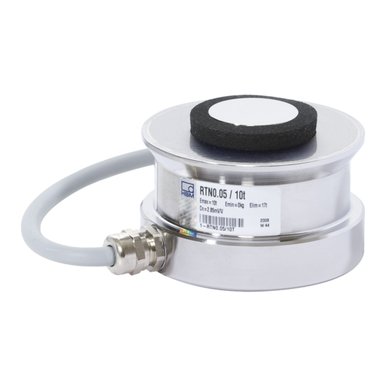
    ANWENDUNG Die Ring-Torsions-Wägezellen RTN sind in ihren verschiedenen Varianten für einen brei­ ten Nennlastbereich verfügbar (1 bis 470 Tonnen). Sie sind geeignet für Behälter­ verwiegung aller Art sowie für große Plattformwaagen. Sie verfügen über einen Körper aus rostfreiem Stahl, die eine hohe Schutzart und damit den Einsatz unter rauen Bedingungen ermöglichen.
  • Seite 28: Montagehinweise

    MONTAGEHINWEISE Bei der Montage der Wägezellen sind folgende Punkte zu beachten: Wägezelle bitte schonend handhaben! Wägezellen sind Präzisionsaufnehmer, die erzielbare Genauigkeit ist daher stark von der korrekten Montage abhängig! Für die Montage der Wägevorrichtung geeignete Hebezeuge verwenden! Wägezelle nicht überlasten, auch nicht kurzzeitig (z. B. durch ungleich verteilte Aufla­ gerlasten)! Bei Richtarbeiten, die die Wägezellen gefährden können, gleich hohe Stützkörper (Dummies) einsetzen!
  • Seite 29 Hinweis Wägezellen sind Präzisions‐Messelemente und verlangen daher eine umsichtige Hand­ habung. Stöße oder Stürze können zu permanenten Schäden am Aufnehmer führen. Sorgen Sie dafür, dass auch bei der Montage keine Überlastung des Aufnehmers auftreten kann. Montagevorbereitungen Die Stellflächen bzw. Fundamente müssen eben und waagrecht sein. Die Aufstandsfläche (Fußplatte der Wägezelle) muss besonderen Anforderungen genügen: Wärmeausdehnungskoeffizient von 11·10 /K;...
  • Seite 30: Elektrischer Anschluss

    ELEKTRISCHER ANSCHLUSS Zur Messsignalverarbeitung können angeschlossen werden: Trägerfrequenz‐Messverstärker Gleichspannungs‐Messverstärker die für DMS‐Messsysteme ausgelegt sind. Bei Einsatz von Elastomerlagern ist die Konstruktion gegenüber dem Fundament isoliert. Beachten sie hier die DIN/VDE 0100, Teil 410 bezüglich eines notwendigen Potenzial­ ausgleichs. Anschluss in Vierleitertechnik Speisung (+) (schwarz) Fühler (+)
  • Seite 31: Steckeranschluss (Optional)

    Steckeranschluss (optional) Steckkontakt 1 = Messsignal (-) Steckkontakt 2 = nicht belegt Steckkontakt 3 = Fühlerleitung (-) Steckkontakt 4 = nicht belegt Steckkontakt 5 = Fühlerleitung (+) Steckkontakt 6 = Speisespannung (+) Steckkontakt 7 = Speisespannung (-) Steckkontakt 8 = Messsignal (+) Abb.
  • Seite 32: Kabelverlängerung Und Kabelkürzung

    Speisung (+) (schwarz) Fühler (+) Speisung (-) (blau) Fühler (-) (rot) Signal (+) (weiß) Signal (-) (gelb) Schirm Klemmenkasten (z. B. “VKK...” oder “VKEX” von HBM) Kabelverlängerung Abb. 5.3 Parallelschaltung mehrerer Aufnehmer Kabelverlängerung und Kabelkürzung Verwenden Sie nur abgeschirmte, kapazitätsarme Messkabel zur Verlängerung. Achten Sie auf eine einwandfreie Verbindung mit geringem Übergangswiderstand.
  • Seite 33 Abweichungen über der spezifizierten Genauigkeit der Wägezelle entstehen. Solche Spannungsstöße kommen in Anlagen z.B. durch Blitzeinschlag oder Schalthandlungen in Leistungsstromkreisen vor und verschwinden direkt nach Störeinwirkung wieder. Dies ist insbesondere bei Kabellängen über 30 m oder Verwendung im Außenbereich zu beach­ ten.
  • Seite 34: Korrosionsschutz Und Wartung

    KORROSIONSSCHUTZ UND WARTUNG Die Wägezelle muss gegen Chemikalien geschützt werden, die den Stahl des Gehäuses oder das Kabel angreifen. Hinweis Säuren und alle Stoffe, die Ionen freisetzen, greifen auch nichtrostende Stähle und deren Schweißnähte an. Die dadurch auftretende Korrosion kann zum Ausfall des Aufnehmers führen. Sehen Sie in diesem Fall entsprechende Schutzmaßnahmen vor.
  • Seite 35: Technische Daten

    TECHNISCHE DATEN Information Weitere Produktinformationen unter www.hbm.com/rtn TECHNISCHE DATEN...
  • Seite 36: Abmessungen Wägezelle Rtn

    ABMESSUNGEN WÄGEZELLE RTN... Lieferumfang Wägezelle mit Anschlusskabel RTN... / ≤4,7 t RTN... / 10 t - 470 t Ansicht X Gewindetiefe 7 mm Kabelbelegung RTN... / 1 t - 470 t (schwarz) Speisung (+) (rot) Signal (+) (blau) Speisung (-) (weiß) Signal (-) (grün‐gelb)
  • Seite 37 RTN... 10,5 2,2 t 10,5 4,7 t 10,5 10 t 15 t 22 t 15 m 33 t 15 m 47 t 15 m 68 t 15 m 100 t 15 m 150 t 220 t 330 t 470 t ABMESSUNGEN WÄGEZELLE RTN...
  • Seite 38: Einbauzubehör

    EINBAUZUBEHÖR Pendellager VPN Lieferumfang: Fußplatte, Pendel, Zentrierbolzen, Zentrierflansch, Ausgleichsbleche, Schmierfett, Schrauben Nähere Informationen in der Montageanleitung der VPN, zu finden auf www.hbm.com/rtn Elastomerlager VEN Lieferumfang: Fußplatte, Elastomer, Zentrierflansch, Zentrierbolzen, Druckstück (>4,7 t), Ausgleichsbleche, Schmierfett, Schrauben Nähere Informationen in der Montageanleitung der VEN, zu finden auf www.hbm.com/rtn EINBAUZUBEHÖR...
  • Seite 39 ENGLISH DEUTSCH FRANÇAIS Notice de montage...
  • Seite 40 TABLE DES MATIÈRES Consignes de sécurité ..........Marquages utilisés .
  • Seite 41: Consignes De Sécurité

    CONSIGNES DE SÉCURITÉ Utilisation conforme Les capteurs de pesage de la série RTN… sont conçus pour des applications de pesage dans le cadre des limites de charge spécifiées dans les caractéristiques techniques. Toute autre utilisation est considérée comme non conforme. Les capteurs de pesage doivent uniquement être manipulés par du personnel qualifié...
  • Seite 42 Prévention des accidents Bien que la charge indiquée dans la plage de destruction corresponde à un multiple de la pleine échelle, il est impératif de respecter les directives pour la prévention des accidents du travail éditées par les caisses professionnelles d'assurance accident. Mesures de sécurité...
  • Seite 43 supposent l'emploi d'un traitement de signal électronique. La sécurité dans ce domaine doit également être conçue, mise en œuvre et prise en charge par l'ingénieur/le construc­ teur/l'exploitant de manière à minimiser les dangers résiduels. Il convient de respecter les réglementations nationales et locales en vigueur. Transformations et modifications Il est interdit de modifier le capteur sur le plan conceptuel ou celui de la sécurité...
  • Seite 44: Marquages Utilisés

    MARQUAGES UTILISÉS Marquages utilisés dans le présent document Les consignes importantes pour votre sécurité sont repérées d'une manière particulière. Respectez impérativement ces consignes pour éviter tout accident et/ou dommage matériel. Symbole Signification Ce marquage signale une situation qui - si les Note dispositions relatives à...
  • Seite 45: Symboles Apposés Sur L'appareil

    Symboles apposés sur l'appareil Marquage CE Le marquage CE permet au constructeur de garantir que son produit est conforme aux exigences des directives européennes correspondantes (la déclaration de conformité est disponible sur le site Internet de HBM (www.hbm.com) sous HBMdoc). Marquage d'élimination des déchets prescrit par la loi Conformément aux réglementations nationales et locales en matière de protection de l'environnement et de recyclage, les...
  • Seite 46: Application

    APPLICATION Les capteurs de pesage à anneau de torsion RTN sont disponibles dans leurs diverses variantes pour une large plage de portées maximales (de 1 à 470 tonnes). Ils sont conçus pour le pesage de cuves de toutes sortes et pour les grands ponts-bascules. Ils ont un corps en acier inoxydable offrant un degré...
  • Seite 47: Instructions De Montage

    INSTRUCTIONS DE MONTAGE Lors du montage des capteurs de pesage, les points suivants doivent être respectés : Manipuler le capteur de pesage avec précaution ! Les capteurs de pesage étant des capteurs de précision, l'exactitude atteignable dé­ pend donc fortement d'une réalisation correcte du montage ! Utiliser des engins de levage adaptés pour le montage du dispositif de pesage ! Ne pas surcharger le capteur de pesage même brièvement (par ex.
  • Seite 48 Note Les capteurs de pesage sont des éléments sensibles de précision et doivent donc être maniés avec précaution. Les chocs et les chutes risquent de provoquer un endom­ magement irréversible du capteur. Veiller à ce que le capteur ne puisse pas être surchargé lors du montage également.
  • Seite 49 Si des forces transverses élevées sont attendues dans l'application, il est conseillé d'utili­ ser les paliers oscillants proposés par HBM afin de réduire les forces transverses géné­ rées par la force normale agissant sur le capteur de pesage. Voir également le chapitre 1 "Consignes de sécurité", page 3. INSTRUCTIONS DE MONTAGE...
  • Seite 50: Raccordement Électrique

    RACCORDEMENT ÉLECTRIQUE Pour traiter les signaux de mesure, il est possible de raccorder : des amplificateurs à fréquence porteuse des amplificateurs à courant continu convenant aux systèmes de mesure à jauges d'extensométrie. En cas d'utilisation de paliers élastomère, la construction est alors isolée de la fondation. Respecter alors la norme DIN/VDE 0100, partie 410, en ce qui concerne la nécessité...
  • Seite 51: Raccordement Sur Connecteur (Option)

    Raccordement sur connecteur (option) Broche 1 = signal de mesure (-) Broche 2 = libre Broche 3 = fil de contre-réaction (-) Broche 4 = libre Broche 5 = fil de contre-réaction (+) Broche 6 = tension d'alimentation (+) Broche 7 = tension d'alimentation (-) Broche 8 = signal de mesure (+) Fig.
  • Seite 52: Rallonge Et Raccourcissement De Câbles

    Alimentation (+) (noir) Contre-réaction (+) Alimentation (-) (bleu) Contre-réaction (-) (rouge) Signal (+) (blanc) Signal (-) (jaune) Blindage Boîtier de raccordement (par ex. "VKK..." ou "VKEX" de HBM) Rallonge de câble Fig. 5.3 Branchement en parallèle de plusieurs capteurs Rallonge et raccourcissement de câbles Utilisez uniquement des câbles de mesure blindés de faible capacité...
  • Seite 53 tension selon EN 61000-4-5 peuvent générer des écarts supérieurs à l'exactitude spécifiée du capteur de pesage. De tels chocs de tension apparaissent dans les installations, par exemple suite à des impacts de foudre ou à des manœuvres dans des circuits de puissance. Ils disparaissent immédiatement après la perturbation. Cela est à prendre en compte en particulier pour les câbles de plus de 30 m ou en cas d'utilisation en extérieur.
  • Seite 54: Protection Contre La Corrosion Et Entretien

    PROTECTION CONTRE LA CORROSION ET ENTRETIEN Le capteur de pesage doit être protégé contre les produits chimiques susceptibles d'at­ taquer l'acier du boîtier ou le câble. Note Les acides et toutes les substances libérant des ions attaquent également les aciers in­ oxydables et leurs cordons de soudure.
  • Seite 55: Caractéristiques Techniques

    CARACTÉRISTIQUES TECHNIQUES Information Pour plus d'informations sur le produit, consulter la page www.hbm.com/rtn CARACTÉRISTIQUES TECHNIQUES...
  • Seite 56: Dimensions Capteur De Pesage Rtn

    DIMENSIONS CAPTEUR DE PESAGE RTN... Étendue de la livraison Capteur de pesage avec câble de raccordement RTN... / ≤4,7 t RTN... / 10 t - 470 t Vue X Profondeur du filet 7 mm Code de câblage RTN... / 1 t - 470 t (noir) Alimentation (+) (rouge)
  • Seite 57 RTN... 10,5 2,2 t 10,5 4,7 t 10,5 10 t 15 t 22 t 15 m 33 t 15 m 47 t 15 m 68 t 15 m 100 t 15 m 150 t 220 t 330 t 470 t DIMENSIONS CAPTEUR DE PESAGE RTN...
  • Seite 58: Accessoires De Montage

    ACCESSOIRES DE MONTAGE Palier oscillant VPN Étendue de la livraison : plaque d'assise, construction pendulaire, boulon de centrage, bride de centrage, tôles de compensation, graisse, vis Pour plus d'informations, consulter la notice de montage du VPN qui est disponible à la page suivante : www.hbm.com/rtn Palier élastomère VEN...
  • Seite 59 ACCESSOIRES DE MONTAGE...
  • Seite 60 HBK - Hottinger Brüel & Kjaer www.hbkworld.com info@hbkworld.com...

Inhaltsverzeichnis