HBK MP60 Bedienungsanleitung
Inhaltsverzeichnis
Verfügbare Sprachen
Verfügbare Sprachen
Quicklinks
Inhaltsverzeichnis

Verwandte Anleitungen für HBK MP60


Inhaltszusammenfassung für HBK MP60
- Seite 1 ENGLISH DEUTSCH Operating Manual Bedienungsanleitung MP60, MP60DP...
- Seite 2 Hottinger Brüel & Kjaer GmbH Im Tiefen See 45 D-64293 Darmstadt Tel. +49 6151 803-0 Fax +49 6151 803-9100 info@hbkworld.com www.hbkworld.com Mat.: DVS: A05958 01 X00 00 04.2023 E Hottinger Brüel & Kjaer GmbH Subject to modifications. All product descriptions are for general information only.
- Seite 3 ENGLISH DEUTSCH Operating Manual MP60, MP60DP...
- Seite 89 ENGLISH DEUTSCH Bedienungsanleitung MP60, MP60DP...
- Seite 90 Versorgungsspannung und Steuerein‐/ausgänge und CAN Schnittstelle ..6.2.1 Externe Versorgungsspannung für die Steuerausgänge (MP60) ..Aufnehmer anschließen ..........
- Seite 91 ........... . . MP60, MP60DP...
-
Seite 92: Sicherheitshinweise
Zuständen oder Datenverlust in der Automatisie rungseinrichtung führen. Bestimmungsgemäße Verwendung Die Module MP60 und MP60DP mit den angeschlossenen Aufnehmern sind ausschließ lich für Messaufgaben und direkt damit verbundene Steuerungsaufgaben zu verwenden. Jeder darüber hinausgehende Gebrauch gilt als nicht bestimmungsgemäß. - Seite 93 Achten Sie beim Reinigen darauf, dass keine Flüssigkeit in das Gerät oder an die An schlüsse gelangt. Restgefahren Der Leistungs‐ und Lieferumfang des MP60 bzw. MP60DP deckt nur einen Teilbereich der Messtechnik ab. Sicherheitstechnische Belange der Messtechnik sind zusätzlich vom Anlagenplaner/Ausrüster/Betreiber so zu planen, zu realisieren und zu verantworten, dass Restgefahren minimiert werden.
- Seite 94 Greenline-Schirmführung verwenden (den Schirm des Aufnehmer kabels auf das Steckergehäuse legen). Die verwendeten Kabel der digitalen Ein‐ und Ausgänge des MP60/MP60DP sollten nicht länger als 30 Meter sein und das Gebäude, in dem die Anlage steht, nicht verlassen. An...
- Seite 95 Rechts‐ und Sicherheitsvorschriften zu beachten. Sinngemäß gilt dies auch bei Verwen dung von Zubehör. Qualifiziertes Personal sind Personen, die mit Aufstellung, Montage, Inbetriebsetzung und Betrieb des Produktes vertraut sind und die über die ihrer Tätigkeit entsprechende Quali fikationen verfügen. MP60, MP60DP SICHERHEITSHINWEISE...
-
Seite 96: Verwendete Kennzeichnungen
Dokumente und Dateien. Auf dem Gerät angebrachte Symbole CE-Kennzeichnung Mit der CE‐Kennzeichnung garantiert der Hersteller, dass sein Produkt den Anforderungen der relevanten EG‐Richtlinien ent spricht (die Konformitätserklärung finden Sie auf der Website von HBM (www.hbm.com) unter HBMdoc). MP60, MP60DP VERWENDETE KENNZEICHNUNGEN... - Seite 97 Gesetzlich vorgeschriebene Kennzeichnung zur Entsorgung Nicht mehr gebrauchsfähige Altgeräte sind gemäß den nationa len und örtlichen Vorschriften für Umweltschutz und Rohstoff rückgewinnung getrennt von regulärem Hausmüll zu entsorgen. MP60, MP60DP VERWENDETE KENNZEICHNUNGEN...
-
Seite 98: Einführung
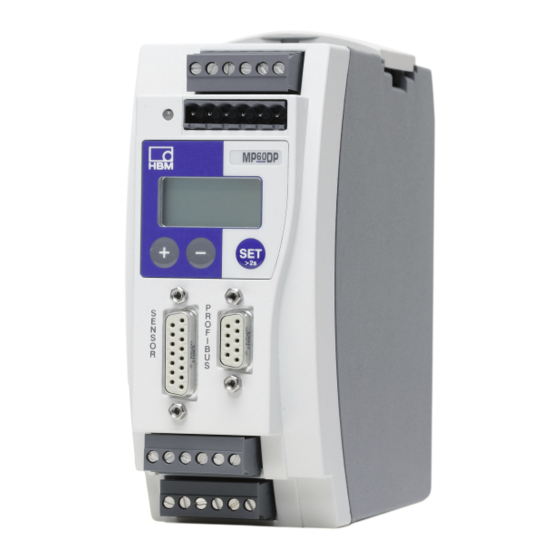
Setup‐Toolkit (Schnittstellenumsetzer USB auf CAN) Bestell‐Nr.: 1-PME-Setup-USB Allgemeines Modul MP60 Die Module MP60 und MP60DP der Produktlinie PME sind Frequenz‐Messmodule, die für den Anschluss von Inkrementalgebern, Frequenzgebern und HBM‐Drehmoment‐Mess flanschen geeignet ist. Eingestellt und parametriert werden die Module über Tastatur und Display oder mit Hilfe des PME-Assistenten. - Seite 99 PRO FIBUS‐DP‐Schnitt stelle (für MP60DP) Abb. 3.1 Blockschaltbild des Moduls MP60 Information Auf dem DIP‐Schalter S12 (MP60) muss der Verstärkertyp MP60 eingestellt sein (siehe auch Seite 13). 1 2 3 4 5 6 Schalterpositionen dürfen nicht verändert werden! MP60, MP60DP...
-
Seite 100: Verstärkereinstellungen Mit Dip-Schaltern
Analogausgang, Synchronisierung, Bus‐Abschlusswiderstand, Flanken steilheit Zum Einstellen der DIP‐Schalter müssen Sie wie in Abb. 4.1 gezeigt vorgehen. Deckel abschrauben Abb. 4.1 Gehäuse öffnen, Lage der DIP‐Schalter Beispiel: bedeutet 1 2 3 4 5 6 Abb. 4.2 Schalterkonvention MP60, MP60DP VERSTÄRKEREINSTELLUNGEN MIT DIP‐SCHALTERN... - Seite 101 1 2 3 4 5 6 1 2 3 4 5 6 Analog Keine Keine Synchronisation Verstärker Abschluss Frequenz ausgang Funktion Funktion (Master) widerstand eingang, (10 V) 120 Ω Referenznull; (AUS) Interne Schalt Schalterpositionen schwelle dürfen nicht (symmetrisch) verändert werden! MP60, MP60DP VERSTÄRKEREINSTELLUNGEN MIT DIP‐SCHALTERN...
-
Seite 102: Verstärker Einstellen
1 2 3 Ua”;siehe Seite 33 Aufnehmerabhängig Zuschalten (F1, F2 Referenznull auf EIN) bei symmetrischen Ausgangssignalen und langen Messleitungen (u100 m). Referenznull 1 2 3 1 2 3 1 2 3 Abb. 4.3 Verstärker einstellen MP60, MP60DP VERSTÄRKEREINSTELLUNGEN MIT DIP‐SCHALTERN... - Seite 103 Synchronisation Master 1 2 3 4 5 6 Slave 1 2 3 4 5 6 Abb. 4.4 Verstärker einstellen (Fortsetzung) Bus‐Abschlusswiderstand Kippschalter für Abschlusswiderstand (siehe auch Seite 24) Abb. 4.5 Schalter für Abschlusswiderstand CAN‐Bus (Prinzipbild) MP60, MP60DP VERSTÄRKEREINSTELLUNGEN MIT DIP‐SCHALTERN...
-
Seite 104: Montage/Demontage
MONTAGE/DEMONTAGE Abb. 5.1 Montieren auf eine Tragschiene Abb. 5.2 Demontage VORSICHT Die Tragschiene muss auf Schutzleiterpotential liegen. MP60, MP60DP MONTAGE/DEMONTAGE... -
Seite 105: Mehrere Module Verbinden
Einbau einer zweiten Feder für eine stabilere Befestigung des Moduls auf der Hutschiene Mehrere Module verbinden Flachbandkabel‐Buchsenstecker Folgegeräte werden über diesen Stecker miteinander verbunden. Farbliche Kennzeich nung an Pin 1 58 mm empfohlener Abstand der Flach bandkabel‐ Buchsenstecker Abb. 5.4 Flachbandkabel anschließen MP60, MP60DP MONTAGE/DEMONTAGE... -
Seite 106: Anschließen
2zeiliges LCD‐Display Drucksensitive Bedientasten Aufnehmeranschluss (15poliger Sub‐D‐Stecker) Steckklemme 3: Potentialgetrennte Steuerein gänge (24 V‐Pegel), Analogausgang Steckklemme 4: Potentialgetrennte Steuerausgänge (24 V‐Pegel), Externe Versorgung der Steuereingänge Potentialtrennung bezogen auf Messverstärker (Messkreis) und Versorgungsspannung Steuereingänge und Steuerausgänge haben gemeinsames Bezugspotential MP60, MP60DP ANSCHLIEßEN... -
Seite 107: Versorgungsspannung Und Steuerein-/Ausgänge Und Can Schnittstelle
Schnittstelle Es stehen vier abziehbare Steckklemmen für das Anschließen zur Verfügung. Spannungsversorgung anschließen WARNUNG Das Modul MP60 muss an eine externe Spannung von 18-30 V (24 V angeschlossen werden. - Aderenden der Spannungsversorgung verdrillen und mit Aderendhülsen versehen. - Aderenden an die Steckklemme 1 schrauben. -
Seite 108: Externe Versorgungsspannung Für Die Steuerausgänge (Mp60)
Die 4 Steckklemmen sind kodiert, um sie verwechslungssicher auf die 4 Buchsen aufstek ken zu können. Die Buchsen sind mit Kodierreitern, die Steckklemmen mit Kodierstiften versehen. 6.2.1 Externe Versorgungsspannung für die Steuerausgänge (MP60) Beispiel: SPS‐Anschluss Modul MP60 Relais max. 100 mA OUT3 max. -
Seite 109: Aufnehmer Anschließen
T34FN Anschluss B Betriebsspannungsnull Messsignal Drehzahl, F2 (+), 25 V (5...30 V) Spit Mess ze‐Spitze (90° phasenverschoben für Drehrich welle tungserkennung) Geh. Kabelschirm Messsignal Drehzahl, F1 (+), 25 V (5...30 V) Spitze‐Spitze Aufnehmerfehler Abb. 6.3 Anschluss MP60 MP60, MP60DP ANSCHLIEßEN... - Seite 110 Messsignal Drehzahl, F2 (+), 90° Nullindex (+) Nullindex (-) Aufnehmerfehler Frequenz, Impulszähler, Inkrementalaufnehmer (asymmetrische Signale) Anschluss A Masse f1, 0° Messsignal Drehzahl, F1 (+), 0° Kabelschirm Geh. f2, 90° Messsignal Drehzahl, F2 (+), 90° Nullindex (+) Aufnehmerfehler Abb. 6.4 Anschluss MP60 MP60, MP60DP ANSCHLIEßEN...
-
Seite 111: Synchronisieren
Der CAN‐Bus wird über die Steckklemme 1 angeschlossen. In einem Bus‐Segment dürfen maximal 32 CAN‐Teilnehmer angeschlossen werden. Der CAN‐Bus benötigt im ersten und letzten Busteilnehmer einen Abschlusswiderstand von 120 Ω. Im Modul MP60 ist ein Abschlusswiderstand integriert, der durch den Kipp schalter S14 aktiviert wird (siehe Seite 15). MP60, MP60DP... - Seite 112 (siehe Seite 15) widerstand zuschalten Abb. 6.7 CAN‐Bus‐Betrieb mit mehreren Modulen (nach Norm maximal 32) Information Ist das erste beziehungsweise letzte Gerät in der Bus‐Leitung kein PME‐Modul, so muss an diesen Fremdgeräten jeweils ein 120 W‐Widerstand zugeschaltet werden. MP60, MP60DP ANSCHLIEßEN...
-
Seite 113: Profibus-Schnittstelle
Setup‐Programm die gewünschte PROFIBUS‐Adresse einstellen. Schließen Sie die PROFIBUS‐Leitung an das Modul MP60DP an. Achten Sie darauf, dass am ersten und letzten PROFIBUS‐Teilnehmer ein Abschlusswiderstand von zuge schaltet ist (am Gehäuse des PROFIBUS‐Steckers befindet sich hierzu üblicherweise ein Schiebeschalter). MP60, MP60DP ANSCHLIEßEN... -
Seite 114: Profibus-Betrieb
Beispiel PROFIBUS‐Ste PROFIBUS‐Ste cker cker Letztes Gerät in Erstes Gerät in der Busleitung der Busleitung Schiebeschalter des PROFIBUS‐ Schiebeschalter des PRO Steckers auf “Widerstand EIN” FIBUS‐Steckers auf “Wider stand EIN” Abb. 6.9 PROFIBUS‐Betrieb MP60, MP60DP ANSCHLIEßEN... -
Seite 115: Einstellen Und Bedienen
Taste kurz drücken -> Wert einzeln weiterschalten Funktion der Tasten − - Vom Messbetrieb in den Einstellbetrieb Parameter/Gruppe auswählen wechseln - Den ersten Parameter innerhalb der Gruppe wählen. - Eingabe bestätigen - Zurück in den Messbetrieb (2 Sek drük ken) MP60, MP60DP EINSTELLEN UND BEDIENEN... - Seite 116 Gewünschten Parameter 0.000 _ _ Hz wählen ↓ ↑ In Eingabemodus gehen Zahlenwert eingeben oder 2.000 0.5 Hz Tabellenwert wählen Bestätigen Zurück in den 2 Sek PME fragt: Speichr? Messbetrieb: NEIN Speichr? speichert Nein gerade MP60, MP60DP EINSTELLEN UND BEDIENEN...
- Seite 117 -18.00 Statusfeld Einheit Symbol im Statusfeld Anzeigemodus kein Zeichen Bruttosignal >T< Nettosignal Maximales Spitzenwertsignal Minimales Spitzenwertsignal wenn aktiv − Spitze/Spitze‐Signal Eingangssignal V oder mA Analogausgangssignal gesetzt, nicht gesetzt Ausg Eing Zustand von Eingang und Ausgang MP60, MP60DP EINSTELLEN UND BEDIENEN...
-
Seite 118: Inbetriebnahme
Erscheint hier die Fehlermeldung HardwOvf, lesen Sie bitte in Kapitel 11 ”Fehlermeldungen/Betriebszustand (LED)”, Seite 82 weiter. Zusätzlich zeigt Ihnen die gelbe LED die Messbereitschaft des MP60 an. Die weiteren Bedeutungen der LED entnehmen Sie dem Kapitel 11 ”Fehlermeldungen/Betriebszustand (LED)”, Seite 82. -
Seite 119: Übersicht Aller Gruppen Und Parameter
Null kNm Tarier. E.Spitzw Nenn kHz SpMomMax E.E/A Nenn kNm SpHltMax E.CAN AufnFhlr SpMomMin E.Zusatz HPTGR SpHltMin HPTGR Shunt ParaCod1 ParaCod2 EingFkt. HPTGR Je nach gewählter Einheit Nur bei MP60DP Voreingestellt mit DIP‐Schaltern, HPTGR mit zurück zur Gruppe MP60, MP60DP... -
Seite 120: Einstellen Aller Parameter
E.E/A Blinkt, wenn Parameterwert editierbar E.CAN drücken Eingabe bestätigen: E.Zusatz Hinweis: +/- = oder Wenn sich eine Gruppe nicht anwählen läßt, überprüfen Sie zurück unter DIALOG, ob die Gruppe freigegeben ist. 2 sec Zurück in den Messbetrieb: HAUPTGRP MP60, MP60DP... - Seite 121 HAUPTGRP 500Hz ↓ ↑ Null kNm 0.000 ‰ ↓ ↑ Bessel ↓ ↑ FiltChar Nenn kHz 0.00000 Butterw l/mi ↓ ↑ Nenn kNm 0.00000 zurück HAUPTGRP ↓ ↑ Aufn Fhlr zurück HAUPTGRP zurück HAUPTGRP je nach gewählter Einheit MP60, MP60DP...
- Seite 122 EinVz ms SpMomMin zurück HAUPTGRP ↓ ↑ AusVz ms SpHltMin Shunt zurück ParaCod1 HAUPTGRP ParaCod2 ↓ ↑ Gilt analog für die Grenzwerte 2...4 frei EingFkt. gesprt. je nach gewählter Einheit bei Ausgang2: F2 bei Ausgang2: Drehrichtung zurück HAUPTGRP MP60, MP60DP...
- Seite 123 ↓ ↑ Brutto langsam ↓ ↑ Ausgabe Tastatur schnell Netto mittel SpwtMax SpwtMin SpwtS-S HW-Vers zurück HAUPTGRP ↓ ↑ AusgR ms ↓ ↑ float PDO‐Frmt int32 ↓ ↑ AutoOPER zurück Nur bei MP60DP HAUPTGRP Je nach gewählter Einheit MP60, MP60DP...
-
Seite 124: Beispiel: Messen Von Md Und N Mit Drehmoment-Aufnehmer T10F (24 V-Versorgung)
Beispiel: Messen von Md und N mit Drehmoment‐Aufnehmer T10F (24 V‐Versorgung) Sowohl T10F als auch der MP60 sind werkseitig auf symmetrische Signale eingestellt. Drehmoment‐Messung Vorbereitung der Messung: Verwenden Sie das Standardkabel md‐Kab149. Schließen Sie die externe Versorgungsspannung von 24 V auch an die Steckklemme 4 an (siehe Seite 21). - Seite 125 6000 U/min = 6000/60 U/sec = 100 U/sec bei 360 Impulsen/Umdrehung: f = 36 kHz In diesem Beispiel soll das F2‐Signal (notwendig zur Drehrichtungserkennung) ausgewer tet werden. 1) Als Eingangsbereich ist die nächst höhere Frequenz zu wählen, hier: 100 kHz MP60, MP60DP...
- Seite 126 6000 U/min entsprechen dann 144 kHz (statt 72 kHz bei F2 = AUS). Schalter: F2 Schalter: Frq x 4 Frequenzanzeige Richtungserkennung nein nein 2). Es wird jede Flanke gezählt, nicht nur die Impulse; dadurch vervierfacht sich die Auflösung MP60, MP60DP...
-
Seite 127: Erklärung Der Wesentlichen Parameter
Definition durch ein (-) angezeigt. Schaltsw Schaltschwelle ab der das Eingangssignal erkannt wird Unterdrückt Störimpulse mit einer Dauer von t3,2 μs GltchFlt Null kHz Null kNm Eingangskennlinie über Aufnehmerkennwerte einstellen Nenn kHz Nenn kNm MP60, MP60DP ERKLÄRUNG DER WESENTLICHEN PARAMETER... - Seite 128 >T<speich Tarawert unmittelbar nach dem Tarieren speichern Filter 0,05 Hz 1 Hz 20 Hz 500 Hz 0,1 Hz 2 Hz 50 Hz 0,2 Hz 5 Hz 100 Hz 0,5 Hz 10 Hz 200 Hz MP60, MP60DP ERKLÄRUNG DER WESENTLICHEN PARAMETER...
- Seite 129 Mit den DIP‐Schaltern S11 legen Sie den Signalmodus für den Analogausgang fest. Folgende Optionen sind möglich: "10 V, "20 mA, 4...20 mA Null % Null V EndwkNm Endw V Endw V Null V Physikalische Null kNm Endw kNm Einheit MP60, MP60DP ERKLÄRUNG DER WESENTLICHEN PARAMETER...
- Seite 130 Änderung erst nach der Verzögerungs zeit (EinVz) am Ausgang aus. AusVz ms Ausschaltverzögerung, wie EinVz SPITZ Eing.Min/ Als Quelle des Spitzenwertsignales kann gewählt werden: Brutto, Netto, SpLöschn Der Spitzenwert kann gelöscht werden. MP60, MP60DP ERKLÄRUNG DER WESENTLICHEN PARAMETER...
- Seite 131 Ausgangssignal wird invertiert (pos.Log) oder nicht inver Aus1...4 tiert (neg.Log). Die aufgeführten Funktionen können den Steuerkontakten (Eingängen/Ausgängen) frei zugeordnet werden. Funktionen Eingangspegel 0 V Eingangspegel 24 V Tarieren bei Übergang von 0 V - 24 V wird die Tarierung gestartet MP60, MP60DP ERKLÄRUNG DER WESENTLICHEN PARAMETER...
- Seite 132 Betriebsart Momentanwert SpMin für SpMin SpHltMax Speicherinhalt SpMax wird Speicherinhalt SpMax wird aktualisiert eingefroren SpHltMin Speicherinhalt SpMin wird Speicherinhalt SpMin wird aktualisiert eingefroren ParaCod1 Auswahl von Parametersätzen und binär codierten Eingängen ParaCod2 Parametersatz ParaCod2 ParaCod1 MP60, MP60DP ERKLÄRUNG DER WESENTLICHEN PARAMETER...
- Seite 133 PDO‐Frmt Das über den CAN‐Bus ausgegebene Signal wird gewählt und als PDO versendet: Brutto, Netto oder Spitzenwert max/min., Spitze/Spitze, AUS, Benutzer AutoOPER wenn aktiviert: automatisch Operational geschaltet PROFI‐Bus Adresse Adresseinstellung von 3 - 123 MP60, MP60DP ERKLÄRUNG DER WESENTLICHEN PARAMETER...
- Seite 134 Î Î Î Î Î Î Î Fundament Î Î Î Î Î Î Î StillAnz Stillstandsanzeige. Ist Stillstand eingetreten und EIN gewählt, erscheint das Zeichen LadnmNul AUS: Nullwertspeicher wird nicht überschrieben bei Parameterwechsel HW‐Synchr Master oder Slave MP60, MP60DP ERKLÄRUNG DER WESENTLICHEN PARAMETER...
-
Seite 135: Schnittstellenbeschreibung Can
SCHNITTSTELLENBESCHREIBUNG CAN Allgemeines Die Module MP60 und MP60DP verfügen über eine eingebaute CAN‐Schnittstelle, über die sowohl Messwerte übertragen werden können als auch die Parametrierung des Mo duls vorgenommen werden kann. Die Baudrate ist wählbar, maximal ist 1 MBaud möglich. Das Protokoll der Schnittstelle orientiert sich am CANopen Standard. -
Seite 136: Parametrierung
Ñ Ñ Ñ Ñ Ñ Ñ Ñ Ñ Ñ Ñ Ñ Ñ Ñ Ñ Ñ Ñ Ñ Schreiben eines Parameters Wert senden (PC oder SPS an MP60/ MP60DP) Ñ Ñ Ñ Ñ Ñ Ñ Ñ Ñ Ñ Ñ Ñ Ñ Ñ Ñ Ñ Ñ Ñ Ñ Ñ Ñ Ñ Ñ Ñ Ñ... - Seite 137 Ñ Ñ Ñ Ñ Ñ Ñ Ñ Ñ Ñ Ñ Ñ Ñ Ñ Ñ Ñ Ñ Ñ Ñ Ñ Ñ Ñ Ñ Ñ Ñ Ñ Quittung (MP60/ MP60DP an PC oder SPS) Ñ Ñ Ñ Ñ Ñ Ñ Ñ Ñ Ñ Ñ Ñ Ñ Ñ Ñ Ñ Ñ Ñ Ñ Ñ Ñ Ñ Ñ Ñ Ñ Ñ...
-
Seite 138: Objektverzeichnis (Kommunikations-Profil-Bereich)
Ñ Ñ Ñ Ñ Ñ Ñ Ñ Version String Ñ Ñ Ñ Ñ Ñ Ñ Ñ Ñ Ñ Ñ Ñ Ñ Ñ Ñ Ñ Ñ Ñ Ñ Ñ Ñ Ñ Ñ Ñ Ñ Ñ Ñ Ñ Ñ MP60, MP60DP SCHNITTSTELLENBESCHREIBUNG CAN... - Seite 139 Ñ Ñ Ñ Ñ Ñ Ñ Ñ Ñ Ñ Ñ Ñ Ñ Ñ Ñ Ñ Ñ Ñ Ñ Ñ Ñ Ñ Ñ Ñ Ñ Ñ Ñ Ñ Ñ Ñ Ñ Ñ Ñ Ñ Ñ Ñ Ñ Ñ 1801 0..2 2. Sende‐PDO‐Parame PDO Comm MP60, MP60DP SCHNITTSTELLENBESCHREIBUNG CAN...
- Seite 140 PDO gültig PDO ungültig RTR erlaubt RTR nicht erlaubt 11 bit ID 29 bit ID 28..0 CAN‐ID PDO Mapping: Index Subindex Name Datentyp 0021 Anzahl gemappter Objekte unsigned8 1. gemapptes Objekt unsigned32 2. gemapptes Objekt unsigned32 unsigned32 MP60, MP60DP SCHNITTSTELLENBESCHREIBUNG CAN...
- Seite 141 Fehlercode ‐ zusätzliche Information: Wert Bedeutung Kein Fehler Übertragungsfehler Systemfehler unbekannter Befehl falsche Parameterzahl falscher Parameterwert Fehler wegen Filterfrequenz Verstärker übersteuert Befehl nicht ausführbar fehlerhafte Kanalwahl Fehler beim Messen Fehler beim Triggern Fehler beim Messbereich Fehler beim Tarieren MP60, MP60DP SCHNITTSTELLENBESCHREIBUNG CAN...
-
Seite 142: Emergency Objekte
Parameter, die auf Messwerte Bezug nehmen, sind ziffernrichtig skaliert als Long (Integer 32 Bit) codiert. Die Dezimalpunktposition ist im Objekt 2120Hex definiert. Alternativ ste hen diese Größen auch als Float‐Werte (IEEE754‐1985 Format 32 Bit) zur Verfügung (siehe Seite 67). Hinweis: rop, rwp: PDO‐Mappbar MP60, MP60DP SCHNITTSTELLENBESCHREIBUNG CAN... - Seite 143 Impuls: 0 Nachkommast. 2006 Wert Analo inte 3 Nachkommastellen gausgang V ger32 2010 Messwert‐Sta unsi Bit 0: Messw. Overflow gned8 Bit 1: Analog Ausg. Overfl. Bit 2: Skalierung fehlerhaft Bit 3: EEPROM Fehler Bit 4..7: Grenzwert 1...4 MP60, MP60DP SCHNITTSTELLENBESCHREIBUNG CAN...
- Seite 144 0: Schreiben = Löschen 2082 Seriennummer vis.string 12 Zeichen 2083 Edit‐Mode ver unsi Messwertanzeige nach be lassen gned8 schreiben mit beliebigem Wert Dialog 2101 Dialog‐Sprache unsi 1500 deutsch gned16 1501 englisch 2103 Passwort inte ger16 MP60, MP60DP SCHNITTSTELLENBESCHREIBUNG CAN...
- Seite 145 Bit 15: Tastatursperre Parameter sätze 2110 Parametersatz unsi 6600: Werkseinstellung aktivieren gned16 6601: Parametersatz 1 6602: Parametersatz 2 6603: Parametersatz 3 6604: Parametersatz 4 2111 Parametersatz unsi s.o. speichern gned16 Anzeige anpassung 2120 Dezimalpunkt‐ unsi 0..5 Position gned16 MP60, MP60DP SCHNITTSTELLENBESCHREIBUNG CAN...
- Seite 146 1631: % 1657: l/mi 2122 Physikalische visible 4 char Einheit String 2131 Messbereich unsi 533: 1 MHz gned16 534: 100 kHz 531: 20 kHz 535: 10 kHz 536: 1 kHz 1646: 5 MImp 1647: 1 GImp MP60, MP60DP SCHNITTSTELLENBESCHREIBUNG CAN...
- Seite 147 Wert in kHz kennwert kHz ger32 2143 Aufnehmer inte Wert z.B. in kN kennwert phy ger32 sik. Einheit 2150 Eingangskenn inte Wert in kHz linie 1. Punkt ger32 2151 Eingangskenn inte Wert z.B. in kN linie 2.Punkt ger32 MP60, MP60DP SCHNITTSTELLENBESCHREIBUNG CAN...
- Seite 148 Ñ Ñ Ñ Ñ Ñ Ñ Ñ Ñ Ñ (Spannung/ 292: 4..20 mA Strom) Ñ Ñ Ñ Ñ Ñ Ñ Ñ Ñ Ñ Ñ Ñ Ñ Ñ Ñ Ñ Ñ Ñ Ñ Ñ Ñ Ñ Ñ Ñ Ñ Ñ Ñ Ñ Ñ MP60, MP60DP SCHNITTSTELLENBESCHREIBUNG CAN...
- Seite 149 2218 Status Grenz unsi wert 1 gned8 Ñ Ñ Ñ Ñ Ñ Ñ Ñ Ñ Ñ Ñ Ñ Ñ Ñ Ñ Ñ Ñ Ñ Ñ Ñ Ñ Ñ Ñ Ñ Ñ Ñ Ñ Ñ Ñ Ñ MP60, MP60DP SCHNITTSTELLENBESCHREIBUNG CAN...
- Seite 150 Ñ Ñ Ñ Ñ Ñ Ñ Ñ Ñ Ñ Grenzwert 3 ger32 Ñ Ñ Ñ Ñ Ñ Ñ Ñ Ñ Ñ Ñ Ñ Ñ Ñ Ñ Ñ Ñ Ñ Ñ Ñ Ñ Ñ Ñ Ñ Ñ Ñ Ñ Ñ Ñ MP60, MP60DP SCHNITTSTELLENBESCHREIBUNG CAN...
- Seite 151 Ñ Ñ Ñ Ñ Ñ Ñ Ñ Ñ Ñ Ñ icher freigeben gned16 0: gesperrt Ñ Ñ Ñ Ñ Ñ Ñ Ñ Ñ Ñ Ñ Ñ Ñ Ñ Ñ Ñ Ñ Ñ Ñ Ñ Ñ Ñ Ñ Ñ Ñ Ñ Ñ Ñ Ñ Ñ MP60, MP60DP SCHNITTSTELLENBESCHREIBUNG CAN...
- Seite 152 Ñ Ñ Ñ Ñ Ñ Ñ Ñ Ñ Ñ gned16 Ñ Ñ Ñ Ñ Ñ Ñ Ñ Ñ Ñ Ñ Ñ Ñ Ñ Ñ Ñ Ñ Ñ Ñ Ñ Ñ Ñ Ñ Ñ Ñ Ñ Ñ Ñ Ñ MP60, MP60DP SCHNITTSTELLENBESCHREIBUNG CAN...
- Seite 153 Ñ Ñ Ñ Ñ Ñ Ñ Ñ Ñ Ñ Ñ satzauswahl 1 Ñ Ñ Ñ Ñ Ñ Ñ Ñ Ñ Ñ Ñ Ñ Ñ Ñ Ñ Ñ Ñ Ñ Ñ Ñ Ñ Ñ Ñ Ñ Ñ Ñ Ñ Ñ Ñ Ñ MP60, MP60DP SCHNITTSTELLENBESCHREIBUNG CAN...
- Seite 154 Ñ Ñ Ñ Ñ Ñ Ñ Ñ Ñ Ñ 2610 Tarieren unsi 1: Tarieren gned8 Ñ Ñ Ñ Ñ Ñ Ñ Ñ Ñ Ñ Ñ Ñ Ñ Ñ Ñ Ñ Ñ Ñ Ñ Ñ Ñ Ñ Ñ Ñ Ñ Ñ Ñ Ñ Ñ MP60, MP60DP SCHNITTSTELLENBESCHREIBUNG CAN...
-
Seite 155: Herstellerspezifische Objekte Im Datenformat Float
Ñ Ñ Ñ Ñ Ñ Ñ Ñ sche Einheit Ñ Ñ Ñ Ñ Ñ Ñ Ñ Ñ Ñ Ñ Ñ Ñ Ñ Ñ Ñ Ñ Ñ Ñ Ñ Ñ Ñ Ñ Ñ Ñ Ñ Ñ Ñ Ñ Ñ MP60, MP60DP SCHNITTSTELLENBESCHREIBUNG CAN... - Seite 156 Ñ Ñ Ñ Ñ Ñ Ñ 3247 Hysterese Grenzwert 4 float Ñ Ñ Ñ Ñ Ñ Ñ Ñ Ñ Ñ Ñ Ñ Ñ Ñ Ñ Ñ Ñ Ñ Ñ Ñ Ñ Ñ Ñ Ñ Ñ Ñ Ñ Ñ Ñ MP60, MP60DP SCHNITTSTELLENBESCHREIBUNG CAN...
-
Seite 157: Beispiele
Einstellen der Filterfrequenz auf 200 Hz. Protokoll an den Verstärker: Identifier 1.Byte 2.Byte 3.Byte 4.Byte 5.Byte 6.Byte 7.Byte 8.Byte 0603 CAN‐ schrei Index Index Subin Low‐Byte High‐ don't care Identifier Low‐ High‐ Byte 2Byte Byte Byte 958 = (3BF Hex) MP60, MP60DP SCHNITTSTELLENBESCHREIBUNG CAN... - Seite 158 Antwort vom Verstärker: Identifier 1.Byte 2.Byte 3.Byte 4.Byte 5.Byte 6.Byte 7.Byte 8.Byte 0583 CAN‐ Quit Index Index Subin don't care Identifier tung Low‐ High‐ schrei Byte Byte MP60, MP60DP SCHNITTSTELLENBESCHREIBUNG CAN...
-
Seite 159: Schnittstellenbeschreibung Profibus (Nur Mp60Dp)
Fügen Sie ein HBM‐Gerät hinzu (Hardwarekatalog). Wählen Sie aus dem Hardwarekatalog die Konfiguration, die Sie auf dem Profibus benötigen. Abb. 10.1 Hardware‐Konfiguration Öffnen Sie durch Doppelklicken der konfigurierten Einträge das Eigenschaftsfenster und wählen Sie die gewünschten Parameter aus. MP60, MP60DP (NUR MP60DP) SCHNITTSTELLENBESCHREIBUNG PROFIBUS... -
Seite 160: Parametrierung
Die Verstärkerparameter werden wie beim MP60DP über Tastatur oder CAN‐Schnittstelle eingestellt. Das Profibus‐DP‐Parametriertelegramm legt einige Parameter für die DP‐ Übertragung fest. Wenn Sie Profibus‐Parametriertools verwenden, die GSD‐Files der GSD‐ Revision 1 verwerten können, stehen folgende Parameter zur Auswahl: MP60, MP60DP (NUR MP60DP) SCHNITTSTELLENBESCHREIBUNG PROFIBUS... - Seite 161 Funktionen im Fehlerfall gegen eine ungewollte Auslösung abzusichern, da sonst z.B. der einmal eingestellte Nullpunkt verloren gehen könnte. Falls Sie ältere Parametriertools einsetzen, müssen die Parameterwerte in Dezimal‐ oder Hexadezimalwerte umgerechnet werden: MP60, MP60DP (NUR MP60DP) SCHNITTSTELLENBESCHREIBUNG PROFIBUS...
- Seite 162 1 = freigegeben Ausgangssteuer wort frei Steuerbits 0 = gesperrt gesperrt gibt Funktion für Parametersatz Steuerung über 3 = freigegeben Ausgangssteuer wort frei wird u.U. von Ihrem Parametriertool sebständig verändert Tab. 10.2 Inhalt des Parametrier‐Telegramms MP60, MP60DP (NUR MP60DP) SCHNITTSTELLENBESCHREIBUNG PROFIBUS...
-
Seite 163: Konfiguration
Nachkommastellenzahl. Die Angaben, ob das 16 Bit oder ein 32 Bit‐Format verwendet wird, sowie die Anzahl der Nachkommastellen wird im Parametrier‐Telegramm festge legt. Im GSD‐File sind typische Kombinationen vordefiniert. Wenn Sie andere Kombinationen benötigen, können Sie anhand der folgenden Spezifikationen das GSD‐File entsprechend erweitern. MP60, MP60DP (NUR MP60DP) SCHNITTSTELLENBESCHREIBUNG PROFIBUS... -
Seite 164: 10.3.1 Definition Eigener Konfigurations-Kombinationen
Eingangswerte: 1(2) Brutto 1(2) Netto 1(2) 1(2) 1(2) Spitze‐Spitze Status1 Status2 Ausgangswerte: Steuerwort 1(2) Grenzwertpegel 1 1(2) Grenzwertpegel 2 1(2) Grenzwertpegel 3 1(2) Grenzwertpegel 4 Tab. 10.3 Auswahl der Dateninhalte über die herstellerspezifischen Daten MP60, MP60DP (NUR MP60DP) SCHNITTSTELLENBESCHREIBUNG PROFIBUS... -
Seite 165: Zyklischer Datenaustausch
(2 Worte, 32 Bit Integer im Zweierkomplement, Kommastelle muss der lesenden Stelle bekannt sein). Für die Umrechnung der Werte in die Festpunktdarstellung wird die Anzahl der Nachkommastellen in der Modulparametrierung (Display, CAN‐Bus) zugrunde gelegt. Status 1 Name Bedeutung MesswOvfl Messwerte übersteuert AOutOvfl Analogausgang übersteuert MP60, MP60DP (NUR MP60DP) SCHNITTSTELLENBESCHREIBUNG PROFIBUS... - Seite 166 Bit 9 Parametersatz‐Nr Status 2 Das Status‐Doppelwort 2 liefert eine detailliertere Fehlerkennzeichung. Name Bedeutung HardwOvfl Übersteuerung Hardware ADCOvfl ADC übersteuert GrossOvfl Bruttosignal übersteuert NetOvfl Nettosignal übersteuert AOutOvfl Analogausgang übersteuert MaxOvfl Maximum übersteuert MinOvfl Minimum übersteuert MP60, MP60DP (NUR MP60DP) SCHNITTSTELLENBESCHREIBUNG PROFIBUS...
-
Seite 167: Bedeutung
0-1 löst Tarierung aus SHUNT Shunt EIN / AUS reserviert CLRMAX 0-1 löscht den Spitzenwertspeicher MAX CLRMIN 0-1 löscht den Spitzenwertspeicher MIN HOLDMAX 1: Spitzenwertspeicher MAX einfrieren HOLDMIN 1: Spitzenwertspeicher MIN einfrieren PAR1 Parametersatz‐Auswahl Bit 1 MP60, MP60DP (NUR MP60DP) SCHNITTSTELLENBESCHREIBUNG PROFIBUS... -
Seite 168: Diagnose
Wert Bedeutung 0..7 Version 1 0..7 Länge der Gerätediagnose ist insgesamt 4 Byte Hardware übersteuert ADC übersteuert Brutto übersteuert Netto übersteuert Analogausgang übersteuert Maximum übersteuert Minimum übersteuert 0..3 Skalierung Eingangskennlinie fehlerhaft Skalierung Ausgangskennlinie fehlerhaft MP60, MP60DP (NUR MP60DP) SCHNITTSTELLENBESCHREIBUNG PROFIBUS... - Seite 169 Octet Wert Bedeutung Nennwert überschritten Werkskalibrierung fehlerhaft Aufnehmer‐Fehler 1...7 Tab. 10.8 Inhalt Diagnose MP60, MP60DP (NUR MP60DP) SCHNITTSTELLENBESCHREIBUNG PROFIBUS...
-
Seite 170: Fehlermeldungen/Betriebszustand (Led)
Min. Spitzenwertsignal SpSp Ovf UrkalFhl − − − − − − − Spitze/Spitze‐Signal ZhlOvfl UrkalFhl − − − − − − − Eingangssignal ZhlOvfl AnlgOvfl − − − − − − − ASkalFhl UrkalFhl Analogausgangssignal Imp, kImp MP60, MP60DP FEHLERMELDUNGEN/BETRIEBSZUSTAND (LED) - Seite 171 ändern (ASkalFhl) (UrKalFhl) Keine gültigen Urkalibrier Neustart, PME an den Hersteller werte (HBM) senden CAN Tx PDOs werden nicht auf dem CAN‐Bus‐Aufbau prüfen Bus abgenommen Auf CAN‐Bus wird ±1000000 ausgegeben Siehe Seite 40 MP60, MP60DP FEHLERMELDUNGEN/BETRIEBSZUSTAND (LED)
- Seite 172 Information Der MP60 kann Aufnehmerfehler, die vom Drehmomentsensor erzeugt werden, signalisie ren. Dazu muss aber das Fehlersignal vom Drehmomentsensor auf Pin 7 der Aufnehmer stecker (15 poliger Sub‐D Stecker) gelegt werden. Zusätzlich ist dann die Funktion “Aufnehmerfehler” im MP60 zu aktivieren.
- Seite 173 DATA_EX (Zyklischer Datenverkehr) ERROR (Bus‐Fehler) Die LED zeigt die Betriebszustände (Messbereit, Overflow etc.) des MP60DP an. Statt des CAN‐Zustandes (wie beim MP60) wird jedoch der Profibus‐Zustand angezeigt. Betriebszustand: LED‐Farbe Zustand Bedeutung Profibus‐Zustand Grün Leuchtet stetig Zustand DATA_EX Gelb Leuchtet stetig Zustände BD_SEAR, WT_PARM, WT_CONF...
-
Seite 174: Stichwortverzeichnis
Eingangskennlinie, 39 Ausgänge, 43 Eingangssignal asymmetrisch / Ausgangs-Steuerkontakte, 43 differentiell, 14 Ausgangskennlinie, 42 Einschaltverzögerung, 42 Einstellbetrieb, 28 Einstellen, 27, 30 Baudrate, 45 Einstellen der Parameter, 32 Bessel, 41 Emergency-Objekt, 54 Butterworth, 41 Entladerate, 43 Fehler, 29 Fehler-Quittung, 49 MP60, MP60DP STICHWORTVERZEICHNIS... - Seite 175 Beschreibung, 39 einstellen, 32 Inbetriebnahme, 30 lesen, schreiben, 48 Passwort, 28, 39 Pegel, 42 Kodierreiter, 20 PROFI-Bus, 45 Kodierstift, 20 Profil, 45 Konfigurieren, 30 Referenznull, 13, 46 Laden, 39 LED, 84, 85 Leitungsabschlusswiderstand, 14 Schalterkonvention, 12 Schaltrichtung, 42 MP60, MP60DP STICHWORTVERZEICHNIS...
- Seite 176 Steuerausgänge, 18 Steckklemmenbelegung, 19, 72, 75, 77, Steuerausgänge, 18, 20 Steuerein- und ausgänge, 18 Steuereingänge, 18, 20, 43 Steuerkontakte, 43 Stillstand, 30 Stillstandsanzeige, 46 Synchronisation, 18, 23 Tarieren, 40 Triggerpegel, 59 Versorgungsspannung, 19 Verstärker einstellen, 14 Verstärkereinstellungen, 12 MP60, MP60DP STICHWORTVERZEICHNIS...
- Seite 177 MP60, MP60DP...