
Verwandte Anleitungen für CLIVET ME2-Y 27M Serie


Inhaltszusammenfassung für CLIVET ME2-Y 27M Serie
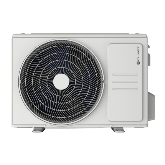
- Seite 1 UNITÀ ESTERNA MONOSplit SCHIARA 2 Serie ME2-Y da 27M a 35M M0KE00001-00 10-2021...
- Seite 2 MATERIALE INFIAMMABILE Indica che l’apparecchio utilizza un refrigerante infiammabile. GARANZIA Il prodotto CLIVET gode di una garanzia convenzionale, valida a partire dalla data di acquisto dell’apparecchio, le cui condizioni sono specificate nelle CONDIZIONI GENERALI DI VENDITA reperibili all’indirizzo www.clivet.com AVVERTENZA –...
- Seite 3 INDICE Generalità ............4 5 Smaltimento ........... 24 Avvertenze generali e regole per la 6 Nozioni sul collegamento delle linee sicurezza frigorifere ............25 1.2 Descrizione componenti del sistema 6.1 Collegamento linee frigorifere 1.3 Accessori 6.1.1 Tagliare i tubi 1.4 Identificazione 6.1.2 Eliminare le sbavature 2 Installazione ...........
-
Seite 4: Generalità
Avvertenze generali e regole per la sicurezza AVVERTENZA – Il presente manuale è proprietà di CLIVET e ne è vietata la riproduzione o la cessione a terzi dei contenuti del presente documento. Tutti i diritti sono riservati. Esso è parte integrante del prodotto; assicurarsi che sia sempre a corredo dell’apparecchio, anche in caso di vendita/trasferimento ad altro proprietario, affinché... - Seite 5 Generalità ATTENZIONE PERICOLO – Quando si collegano le linee frigorifere, evitare l’ingresso nell’unità di sostanze o gas diversi dal refrigerante specificato. La presenza di altri gas o sostanze può ridurre le prestazioni dell’unità e causare un innalzamento anomalo della pressione nel ciclo di refrigerazione. Questo può generare rischi di esplosione e conseguenti lesioni.
- Seite 6 Generalità Descrizione componenti del sistema Fig. 1 A Ingresso aria 6 Tubo flessibile di drenaggio B Uscita aria 7 Collegamento elettrico 8 Linee frigorifere 1 Piastra di montaggio a parete 9 Alimentazione unità esterna 2 Unità interna 10 Telecomando 3 Feritoia di ventilazione 11 Supporto del telecomando 4 Filtro 12 Display led SCHIARA 2...
- Seite 7 Generalità Accessori Il condizionatore è provvisto dei seguenti accessori. Per installarlo, usare tutti i componenti e gli accessori d’installazione specificati. Un’installazione non corretta può provocare perdite d’acqua, scosse elettriche e incendi, o causare il malfunzionamento dell’apparecchio. Descrizione Aspetto Quantità Guarnizione Raccordo di scarico Manuale installazione uso e manutenzione...
- Seite 8 Generalità Identificazione L’unita interna e l’unità esterna sono identificabili attraverso l’etichetta matricolare che riporta i dati tecnici, prestazionali dell’apparecchio e quanto richiesto dalla Legislazione in vigore. Etichetta matricolare Unità interna Etichetta matricolare Unità esterna Fig. 2 PRESTARE CAUTELA La manomissione, l’asportazione, la mancanza delle etichette di identificazione o quant’altro non permetta la sicura identificazione del prodotto, rende difficoltosa qualsiasi operazione di installazione e manutenzione.
- Seite 9 Installazione 2 INSTALLAZIONE Installazione - avvertenze preliminari AVVERTENZA Ricevimento del prodotto Prima di installare l’unità interna, consultare l’etichetta sulla confezione del prodotto L’apparecchio viene fornito imballato in più colli. La per controllare che il numero di modello movimentazione deve essere effettuata con appropriati corrisponda a quello dell’unità...
-
Seite 10: Installazione Unità Esterna
Installazione Installazione unità esterna CONSIDERAZIONI SPECIALI PER CONDIZIONI ATMOSFERICHE ESTREME Se l’unità è esposta a forte vento: 2.4.1 Luogo di installazione Installare l’unità in modo che il ventilatore dell’uscita aria si trovi a 90° rispetto alla direzione del vento. Se Prima di installare l’unità... -
Seite 11: Montaggio Dell'unità Esterna
Installazione 2.4.2 Montaggio del raccordo di scarico 2.4.3 Montaggio dell’unità esterna Le unità con pompa di calore richiedono un raccordo L’unità esterna può essere fissata al pavimento o a una di scarico. Prima di fissare l’unità esterna in posizione, staffa montata a parete. è... -
Seite 12: Collegamenti Elettrici
Installazione 2.4.4 Collegamenti elettrici 3 Pulire i fori dalla polvere di calcestruzzo. 4 Inserire un dado all’estremità di ogni tassello a Per l’alimentazione dell’unità esterna sono necessari dei espansione. cavi con le seguenti caratteristiche: 5 Martellare i tasselli a espansione nei fori realizzati. Alimentazione da rete Unità... - Seite 13 Installazione Lo schema elettrico dell’unità esterna Morsettiera unità ESTERNA Morsettiera unità ESTERNA si trova all’interno del coperchio della morsettiera. 1(L) 2(N) Coperchio Vite segnale alimentazione segnale alimentazione Fig. 7 dalla morsettiera 230V~50Hz dalla morsettiera 4 Abbinare i colori/le etichette dei cavi alle etichette della dell’unità...
-
Seite 14: Evacuazione Dell'aria
Messa in servizio 3 MESSA IN SERVIZIO 4 Attivare la pompa da vuoto per evacuare il sistema. 5 Tenere in funzione la pompa da vuoto per almeno 15 minuti, o finché l’indicatore del manometro di bassa Evacuazione dell’aria pressione segna -76 cmHG (10 Pa). -
Seite 15: Controllo Di Dispersioni Elettriche E Perdite Di Gas
Messa in servizio 3.1.1 Carica di refrigerante DURANTE LA PROVA DI FUNZIONAMENTO Controllo delle dispersioni elettriche L’apparecchio viene precaricato in fabbrica con una Durante la prova di funzionamento, usare un’elettrosonda quantità di refrigerante sufficiente per una lunghezza dei e un multimetro per condurre un test completo della tubi fino a 5 metri. -
Seite 16: Messa In Servizio
Messa in servizio – COOL – Selezionare la temperatura più bassa possibile 5 Al termine della prova di funzionamento, se tutti – HEAT – Selezionare la temperatura più alta i controlli elencati hanno avuto esito positivo, possibile procedere come segue: –... -
Seite 17: Ricerca Guasti
Manutenzione 4 MANUTENZIONE È buona norma pulire periodicamente sia le parti interne che quelle esterne dell’apparecchio. Questo ne garantisce il buon funzionamento e la durata nel tempo. Eseguire la manutenzione periodica dell’apparecchio secondo quanto previsto dalla normativa vigente. La manutenzione deve essere effettuata da personale tecnico qualificato. ATTENZIONE PERICOLO ELETTRICO Prima delle operazioni di pulizia o manutenzione, spegnere sempre il condizionatore e staccarlo dalla rete elettrica. - Seite 18 Manutenzione Anomalie Possibili cause Rimedi Interruzione di corrente Attendere il ripristino della corrente elettrica L’unità è spenta Accendere l’apparecchio Il fusibile è bruciato Sostituire il fusibile (Centro di Assistenza) Le batterie del telecomando sono L’unità non funziona Sostituire le batterie scariche È...
- Seite 19 Manutenzione Segnalazioni di errore unità esterna SEGNALAZIONE LED SULLA SCHEDA (solo su unità 35M) Lampeggio = errore viene visualizzato sull’unità interna Lampeggio lento = stand-by LED acceso = unità ON Codice errore Descrizione EC 51 Malfunzionamento EEPROM esterno EL 01 Errore di comunicazione delle unità...
- Seite 20 Manutenzione Operare in sicurezza in presenza di refrigerante R32 in quanto durante queste operazioni il refrigerante infiammabile potrebbe fuoriuscire nello spazio circostante. MATERIALE INFIAMMABILE Prima di iniziare l’intervento, si dovrà ispezionare l’area Il refrigerante utilizzato all’interno di questa intorno all’apparecchio per verificare che non presenti unità...
- Seite 21 Manutenzione La situazione dovrà essere comunicata al proprietario parti specificate dal fabbricante. Altri componenti dell’apparecchiatura in modo che tutte le persone possono causare l’ignizione del refrigerante rilasciato interessate possano essere debitamente informate. nell’atmosfera. Cablaggio Controlli di sicurezza iniziali: – controllare che i condensatori siano scarichi: Controllare che il cablaggio non sia esposto a usura, questa procedura deve essere eseguita in modo corrosione, pressione eccessiva, vibrazioni, bordi taglienti...
- Seite 22 Manutenzione Dismissione – aprire il circuito con un’operazione di taglio o brasatura. Prima di eseguire questa procedura, è essenziale che il tecnico abbia totale dimestichezza con l’attrezzatura e La carica di refrigerante potrà essere recuperata nelle tutti i suoi componenti. Si raccomanda di recuperare tutti apposite bombole.
- Seite 23 Manutenzione Etichettatura Trasporto, marcatura e stoccaggio delle unità L’apparecchio deve essere etichettato per segnalare che è stato dismesso e svuotato dal refrigerante. 1 Trasporto di apparecchiature contenenti refrigeranti L’etichetta dovrà essere datata e firmata. Controllare infiammabili che sull’apparecchio siano applicate etichette indicanti il contenuto di refrigerante infiammabile.
-
Seite 24: Smaltimento
Smaltimento 5 SMALTIMENTO Il produttore è iscritto al Registro Nazionale AEE, in RAEE professionali: tutti i RAEE diversi da quelli provenienti conformità all’attuazione della direttiva 2012/19/UE e delle dai nuclei domestici di cui al punto sopra. relative norme nazionali vigenti sui rifiuti di apparecchiature Queste apparecchiature possono contenere: elettriche ed elettroniche. - Seite 25 Nozioni sul collegamento delle linee frigorifere 6 NOZIONI SUL COLLEGAMENTO DELLE LINEE FRIGORIFERE La lunghezza dei tubi del refrigerante incide sulle prestazioni e sull’efficienza energetica dell’unità. L’efficienza nominale viene testata su unità i cui tubi hanno una lunghezza di 5 metri. Per le aree tropicali, la lunghezza massima del tubo del refrigerante non deve superare i 10 metri.
- Seite 26 Nozioni sul collegamento delle linee frigorifere 6.1.3 Svasare le estremità dei tubi Una svasatura corretta è essenziale per una perfetta tenuta della guarnizione. 1 Dopo avere rimosso le sbavature dal tubo tagliato, sigillare le estremità con del nastro in PVC per impedire l’ingresso di materiali estranei.
-
Seite 27: Coppie Di Serraggio
Nozioni sul collegamento delle linee frigorifere 6.1.4 Collegare i tubi Collegamento dei tubi all’unità interna Quando si collegano i tubi del refrigerante, fare attenzione a non usare una coppia di serraggio eccessiva o a non 1 Allineare il centro dei due tubi da collegare. eseguire altre operazioni che possano danneggiarli. - Seite 28 Collegamento dei tubi all’unità esterna 1 Svitare il coperchio del gruppo valvola sul lato dell’unità esterna. Coperchio del gruppo valvole Fig. 22 2 Rimuovere i cappucci di protezione dalle estremità delle valvole. Fig. 23 3 Applicare un pò di olio lubrificante solo sulla superficie interna della svasatura (B).
-
Seite 29: Informazioni Tecniche
Informazioni tecniche 7 INFORMAZIONI TECNICHE Caratteristiche tecniche (MONOSplit) Unità Linee frigorifere inch Ø 1/4” Ø 1/4” Linea liquido Ø 6,35 Ø 6,35 inch Ø 3/8” Ø 3/8” Linea gas Ø 9,52 Ø 9,52 Lunghezza equivalente max Max. dislivello unità esterna / unità interna ±10 ±10 Precarica refrigerante... - Seite 30 Allegati 8 ALLEGATI Schemi elettrici unità esterna (27M - 35M) SERIE GRANDEZZA ME2-Y 27M - 35M...
- Seite 31 Allegati...
- Seite 32 E IL BENESSERE DELL’INDIVIDUO E DELL’AMBIENTE www.clivet.com vendita e assistenza PRONTO CLIVET ASSISTENZA DEDICATA: PRONTO CLIVET Assistenza SPLIT Clivet (solo Italia): Tel. 041/5099169 Lu-Ve 09:00-20:00, Sa 09:00-12:00 (festivi esclusi) split@clivet.support CLIVET SPA Via Camp Lonc 25, Z.I. Villapaiera 32032 Feltre (BL) - Italy Tel.
-
Seite 33: Outdoor Unit
OUTDOOR UNIT MONOSplit SCHIARA 2 ME2-Y series from 27M to 35M... - Seite 34 Indicates that the appliance uses a flammable refrigerant. WARRANTY The product CLIVET is covered by a conventional warranty, valid from the date of purchase of the appliance, the conditions of which are specified in the GENERAL CONDITIONS OF SALE available at www.clivet.com WARNING –...
- Seite 35 INDEX General Details ..........4 5 Disposal ............24 General warnings and safety rules 6 Notions on refrigerant piping connection .. 25 1.2 Description of system components 6.1 Refrigerant piping connections 1.3 Accessories 6.1.1 Cut the pipes 1.4 Identification 6.1.2 Eliminate smudges 2 Installation ............
-
Seite 36: General Details
WARNING – This manual is the property of CLIVET and reproduction or transfer to third parties of the contents of this document is prohibited. All rights reserved. It is an integral part of the product; make sure that it is always supplied with the appliance, even in case of sale/transfer to another owner, so that it can be consulted by the user or by personnel authorized to carry out maintenance and repairs. - Seite 37 General Details CAUTION DANGER – When connecting refrigerant piping,keep substances or gases other than the specified refrigerant from entering the unit. The presence of other gases or substances can reduce unit performance and cause an abnormal increase in pressure in the refrigeration cycle. This can lead to explosion hazards and resulting injuries. –...
- Seite 38 General Details Description of system components Fig. 1 Air inlet 6 Flexible drainage hose Air outlet 7 Electrical connection 8 Refrigerant piping 1 Wall mounting plate 9 Outdoor unit power supply 2 Indoor unit 10 Remote control 3 Ventilation slit 11 Remote control support 4 Filter 12 Display LED SCHIARA 2...
-
Seite 39: Accessories
General Details Accessories The air conditioner is equipped with the following accessories. Use all specified installation components and accessories to install it. Incorrect installation may cause water leakage, electric shock and fire, or cause the unit to malfunction. Description Aspect Quantity Gasket Exhaust fitting... - Seite 40 General Details Identification The indoor unit and the outdoor unit can be identified by the serial number label that shows the technical and perfor- mance data of the unit and what is required by the legislation in force. Serial number label Indoor unit Serial number label Outdoor unit...
-
Seite 41: Size And Weight
Installation 2 INSTALLATION Installation - preliminary warnings WARNING Product receiving Before installing the indoor unit, consult the label on the product package to check that the The appliance is supplied packed in several parcels. model number matches the model number of Handling must be carried out by appropriate means in the outdoor unit. -
Seite 42: Outdoor Unit Installation
Installation Outdoor unit installation SPECIAL CONSIDERATIONS FOR EXTREME WEATHER CONDITIONS If the unit is exposed to strong wind: 2.4.1 Installation Site Install the unit so that the air outlet fan is 90° to the direction of the wind. If necessary, place a barrier in front Before installing the outdoor unit, you must choose an of the unit to protect it from particularly strong winds. - Seite 43 Installation 2.4.2 Installation of the drain connection 2.4.3 Mounting the outdoor unit Units with heat pump require a drain connection. Before The outdoor unit can be fixed to the floor or to a wall fixing the outdoor unit in place, you must install the drain mounted bracket.
-
Seite 44: Electrical Connections
Installation 2.4.4 Electrical connections 4 Insert a nut at the end of each expansion block. 5 Hammer the expansion anchors into the holes made. Cables with the following characteristics are required to power the outdoor unit: 6 Remove the nuts from the expansion anchors and place the outdoor unit on the anchors. - Seite 45 Installation The wiring diagram of the outdoor OUTSIDE unit terminal block Morsettiera unità ESTERNA unit is located inside the terminal box cover. 1(L) 2(N) Cover Screw signal power supply segnale alimentazione Fig. 7 dalla morsettiera 230V~50Hz from the terminal block of 4 Match the colours/labels of the cables to the labels dell’unità...
-
Seite 46: Starting Up The System
Starting up the system 3 STARTING UP THE SYSTEM 3 Open the low pressure side of the manifold gauge assembly. Keep the high pressure side closed. 4 Activate the vacuum pump to evacuate the system. Air evacuation 5 Keep the vacuum pump running for at least 15 minutes, or until the low pressure gauge indicator The presence of air and foreign substances in the reads -76 cmHG (10... -
Seite 47: Function Test
Starting up the system 3.1.1 Refrigerant charge DURING THE OPERATIONAL TEST Electrical dispersion control The unit is factory pre-charged with a sufficient quantity During the operational test, use an electrode and of refrigerant for pipe length up to 5 metres. multimeter to conduct a complete electrical leakage test. - Seite 48 Starting up the system 4 Leave each function active for 5 minutes and perform IF THE ROOM TEMPERATURE IS BELOW 16°C the following checks: If the room temperature is below 16°C, you cannot use the remote control to activate the cooling function (COOL). List of checks to be performed YES/NO In this case, you can use the MANUAL CONTROL button...
- Seite 49 Maintenance 4 MAINTENANCE It is good practice to periodically clean both the internal and external parts of the appliance. This guarantees its proper functioning and durability. Carry out periodic maintenance of the appliance in accordance with the regulations in force. Maintenance must be carried out by qualified technical personnel.
- Seite 50 Maintenance Anomalies Possible causes Remedies The amount of refrigerant in the system Check for leaks and top up the coolant (Service is excessive or insufficient Centre) Incompressible gas has entered or Evacuate the system and recharge the The unit starts or stops moisture has penetrated the system.
- Seite 51 Maintenance Outdoor unit error messages Led signaling on the board (only on 35M unit) Flashing= error displayed on the indoor unit Slow flashing = stand-by LED on = unit ON Error code Description EC 51 Outdoor EEPROM malfunction EL 01 Indoor / outdoor units communication error PC 40 Communication malfunction between IPM board and outdoor main board...
- Seite 52 Maintenance Operate safely with R32 refrigerant present Area ventilation FLAMMABLE MATERIAL Before working on the system or performing hot The refrigerant used inside this unit is operations, make sure the area is open or adequately flammable. A coolant leak that is exposed to ventilated.
- Seite 53 Maintenance Repair of sealed components Leak detection methods The following leak detection methods are considered 10.1 While repairing sealed components, all electrical acceptable for systems containing flammable refrigerants. utilities must be disconnected from the equipment Electronic leak detectors can be used to detect before removing the sealing covers, etc.
- Seite 54 Maintenance Charging operations 10 After filling the cylinders correctly and completing the procedure, transfer the cylinders and equipment from In addition to conventional charging procedures, it is the site as soon as possible and close all isolation recommended to follow the ensuing guidelines: valves on the equipment.
- Seite 55 Maintenance Transport, marking and storage of units 1 Transport equipment containing flammable refrigerants – Follow applicable regulations related transporting these materials 2 Markings and signage on equipment – Observe the regulations in force 3 Disposing equipment containing flammable refrigerants – Comply with national regulations 4 Equipment storage –...
- Seite 56 Disposal 5 DISPOSAL The manufacturer is registered on the National EEE Register, Professional WEEE: all WEEE which comes from something in compliance with implementation of Directive 2012/19/EU other than private households. and pertinent national regulations on electrical and electronic This equipment may contain: equipment waste.
- Seite 57 Notions on refrigerant piping connection 6 NOTIONS ON REFRIGERANT PIPING CONNECTION The length of the refrigerant pipes affects performance and energy efficiency of the unit. The nominal efficiency is tested on units whose pipes are 5 meters long. For tropical areas, the maximum length of the coolant pipe must not exceed 10 metres. Refer to the following table for specifications on maximum pipe length and height difference Max equivalent length Max.
- Seite 58 Notions on refrigerant piping connection 6.1.3 Countersink the ends of the pipes Correct flaring is essential to perfectly seal the gasket. 1 After removing burrs from the cut pipe, seal the ends with PVC tape to prevent foreign materials from entering. 2 Wrap the pipe in an insulating material.
- Seite 59 Notions on refrigerant piping connection 6.1.4 Connect the pipes Connecting the pipes to the indoor unit When connecting the coolant pipes, be careful not to use excessive torque or perform other operations that may 1 Align the centre of the two pipes to be connected. damage them.
- Seite 60 Notions on refrigerant piping connection Connecting the pipes to the outdoor unit 1 Unscrew the valve unit cover on the side of the outdoor unit. Valve group cover Fig. 22 2 Remove the protective caps from the valve ends. 3 Apply a little lubricating oil only to the inner surface of Fig.
-
Seite 61: Technical Data
Technical data 7 TECHNICAL DATA Technical features (MONOSplit) Unit Refrigerant piping inch Ø 1/4” Ø 1/4” Liquid line Ø 6.35 Ø 6.35 inch Ø 3/8” Ø 3/8” Gas line Ø 9.52 Ø 9.52 Max equivalent length Max. height difference outdoor unit / indoor unit ±10 ±10 Refrigerant pre-charge... - Seite 62 Attachments 8 ATTACHMENTS Outdoor Unit Wiring Diagrams (27M - 35M) SERIES SIZE ME2-Y 27M - 35M...
- Seite 63 Attachments...
- Seite 64 FOR 30 YEARS WE HAVE BEEN OFFERING SOLUTIONS FOR SUSTAINABLE COMFORT THE WELL-BEING OF PEOPLE AND THE ENVIRONMENT www.clivet.com sales and service CLIVET SPA Via Camp Lonc 25, Z.I. Villapaiera 32032 Feltre (BL) - Italy Tel. +39 0439 3131 - Fax +39 0439 313300 info@clivet.it...
-
Seite 65: Unité Externe
UNITÉ EXTERNE MONOSplit SCHIARA 2 Série ME2-Y de 27M à 35M... - Seite 66 – Le produit doit être utilisé pour l'usage prévu par CLIVET et pour lequel il a été expressément réalisé. Toute responsabilité contractuelle et extra-contractuelle de CLIVET pour des dommages corporels ou...
- Seite 67 INDEX Généralités ............. 4 5 Élimination ............24 Avertissements généraux et consignes 6 Notions sur le raccordement des de sécurité lignes frigorifiques......... 25 1.2 Description des composants du système 6.1 Raccordement des lignes frigorifiques 1.3 Accessoires 6.1.1 Couper les tuyaux 1.4 Identification 6.1.2 Éliminer les bavures 2 Installation ............
-
Seite 68: Généralités
MISE EN GARDE – Ce manuel est la propriété de CLIVET et sa reproduction ou le transfert à des tiers du contenu de ce document est interdit. Tous les droits sont réservés. Il fait partie intégrante du produit ; il faut donc s’assurer qu'il est toujours fourni avec l'appareil, même en cas de vente/transfert à... - Seite 69 Généralités ATTENTION DANGER – Lors du raccordement des lignes frigorifiques, éviter l’entrée de substances ou de gaz autres que le réfrigérant spécifié dans l'unité. La présence d'autres gaz ou de substances peut réduire les performances de l'unité et provoquer une augmentation anormale de la pression dans le cycle de réfrigération. Cela peut entraîner des risques d'explosion et des blessures consécutives.
- Seite 70 Généralités Description des composants du système Fig. 1 Entrée air 6 Tuyau flexible de drainage Sortie air 7 Branchement électrique 8 Lignes frigorifiques 1 Plaque pour le montage mural 9 Alimentation des unités externes 2 Unité interne 10 Télécommande 3 Volet de ventilation 11 Support de la télécommande 4 Filtre 12 Écran LED SCHIARA 2...
- Seite 71 Généralités Accessoires Le climatiseur est équipé des accessoires suivants. Pour l'installer, il faut utiliser toutes les pièces et accessoires d'installation spécifiés. Une mauvaise installation incorrecte entraîner des fuites d'eau, des décharges électriques et des incendies, ou provoquer un dysfonctionnement de l'appareil. Description Aspect Quantité...
- Seite 72 Généralités Identification L'unité interne et l'unité externe sont identifiables au moyen de l'étiquette du numéro de série qui indique les données techniques, les performances de l'appareil et ce qui est requis par la législation en vigueur en la matière. Étiquette du numéro de série Unité...
-
Seite 73: Réception Du Produit
Installation 2 INSTALLATION Installation - mises en garde préliminaires Réception du produit MISE EN GARDE L'appareil est livré emballé dans plusieurs colis. Avant d'installer l'unité interne, il faut vérifier La manutention doit être effectuée avec des engins l'étiquette située sur l'emballage du produit de appropriés compte tenu du poids total du colis. -
Seite 74: Lieu D'installation
Installation Installation unité externe CONSIDÉRATIONS PARTICULIÈRES POUR DES CONDITIONS ATMOSPHÉRIQUES EXTRÊMES Si l'unité est exposée à un vent fort : 2.4.1 Lieu d’installation Il faut installer l'unité de sorte que le ventilateur de sortie de l'air soit à 90° par rapport à la direction du vent. Avant d'installer l'unité... - Seite 75 Installation 2.4.2 Montage du raccord d’évacuation 2.4.3 Montage de l’unité externe Les unités avec pompe à chaleur nécessitent un raccord L'unité externe peut être fixée au sol ou à un support d’évacuation. Avant de fixer l'unité externe dans sa mural. position, il faut installer le raccord d’évacuation à...
-
Seite 76: Branchements Électriques
Installation 2.4.4 Branchements électriques 4 Insérer un écrou à l'extrémité de chaque cheville à expansion. Pour alimenter l'unité externe, des câbles ayant les 5 Marteler les chevilles à expansion dans les trous caractéristiques suivantes sont nécessaires : réalisés. Alimentation secteur Unité... - Seite 77 Installation Le schéma électrique de l'unité Bornier unité EXTERNE Morsettiera unità ESTERNA externe se trouve à l'intérieur du couvercle du bornier. 1(L) 2(N) Couvercle signal alimentation segnale alimentazione Fig. 7 dalla morsettiera 230V~50Hz du bornier de l'unité 4 Associer les couleurs/les étiquettes des fils aux dell’unità...
-
Seite 78: Mise En Service
Mise en service 3 MISE EN SERVICE 4 Actionner la pompe à vide pour évacuer le système. 5 Faire fonctionner la pompe à vide pendant au moins 15 minutes, ou jusqu'à ce que le manomètre de basse Évacuation de l'air pression indique -76 cmHG (10 Pa). -
Seite 79: Essai De Fonctionnement
Mise en service 3.1.1 Charge de réfrigérant PENDANT L’ESSAI DE FONCTIONNEMENT Contrôle des dispersions électriques L'appareil est préchargé en usine avec une quantité de Pendant l’essai de fonctionnement, utiliser une sonde réfrigérant suffisante pour une longueur de tuyaux allant électrique et un multimètre pour effectuer un essai jusqu'à... - Seite 80 Mise en service 3 Appuyer sur la touche MODE pour faire défiler les 5 À la fin de l’essai de fonctionnement, si toutes les fonctions suivantes, une à la fois : contrôles répertoriés ont été positifs, il faut procéder comme suit : –...
-
Seite 81: Diagnostic Des Pannes
Entretien 4 ENTRETIEN Il est recommandé de nettoyer périodiquement les parties internes et externes de l'unité. Cela garantit son bon fonctionnement et sa durée dans le temps. Effectuer un entretien périodique de l'unité conformément à la réglementation en vigueur. L’entretien doit être effectué par un personnel technique qualifié. ATTENTION DANGER ÉLECTRIQUE Avant les opérations de nettoyage ou d'entretien, il faut toujours éteindre le climatiseur et le débrancher du secteur. - Seite 82 Entretien Anomalies Causes possibles Remèdes Coupure de courant Attendre que le courant soit rétabli L'unité est éteinte Allumer l’unité Le fusible est grillé Remplacer le fusible (Centre de Service) Les piles de la télécommande sont L'unité ne fonctionne pas Remplacer les piles épuisées La fonction de protection avec retard de Attendre trois minutes avant de redémarrer...
- Seite 83 Entretien Signalisations d’erreur de l’unité externe Signalisation DEL sur la carte (uniquement sur les unités 35M) Clignotant = erreur affiché sur l’unité intérieure Clignotant lent = stand-by DEL allumée = unité allumée Code d’erreur Description EC 51 Dysfonctionnement EEPROM unité extérieure EL 01 Erreur communication unités intérieure / extérieure PC 40...
- Seite 84 Entretien Intervenir en toute sécurité en présence de réfrigérant R32 démontage et d'élimination, car le réfrigérant inflammable pourrait s'échapper dans l'espace environnant pendant MATÉRIAU INFLAMMABLE ces opérations. Avant de commencer l'intervention, Le réfrigérant utilisé à l'intérieur de cette il faudra inspecter la zone autour de l'appareil pour unité...
- Seite 85 Entretien mais il est nécessaire de maintenir le système en marche, inflammable. Le testeur doit avoir les caractéristiques il faudra adopter une solution temporaire appropriée. nominales correctes. La situation devra être communiquée au propriétaire de Pour remplacer des composants, n'utiliser que les pièces l'équipement afin que toutes les personnes concernées spécifiées par le fabricant.
- Seite 86 Entretien Mise au rebut – évacuer ; – purger à nouveau avec du gaz inerte ; Avant d'effectuer cette procédure, il est essentiel que le technicien connaisse parfaitement l'équipement et tous – ouvrir le circuit en effectuant une opération de ses composants.
- Seite 87 Entretien Étiquetage Transport, marquage et stockage des unités L'appareil doit être étiqueté pour indiquer qu'il a été mis 1 Transport d’appareils contenant des réfrigérants hors service et vidé du réfrigérant. L'étiquette devra être inflammables datée et signée. Vérifier que les étiquettes indiquant le –...
- Seite 88 Élimination 5 ÉLIMINATION Le producteur est inscrit dans le Registre National EEE, Les DEEE professionnels : tous les DEEE autres que ceux conformément à l’application de la directive 2012/19/UE provenant des foyers domestiques mentionnés au point et des réglementations nationales correspondantes en ci-dessus.
- Seite 89 Notions sur le raccordement des lignes frigorifiques 6 NOTIONS SUR LE RACCORDEMENT DES LIGNES FRIGORIFIQUES La longueur des tuyaux du réfrigérant affecte les performances et l'efficacité énergétique de l'unité. L'efficacité nominale est testée sur des unités dont les tuyaux ont 5 mètres de long. Pour les zones tropicales, la longueur maximale du tuyau du réfrigérant ne doit pas dépasser les 10 mètres.
- Seite 90 Notions sur le raccordement des lignes frigorifiques 6.1.3 Évaser les extrémités des tuyaux Un évasement correct est essentiel pour une parfaite étanchéité du joint. 1 Après avoir éliminé les bavures du tuyau coupé, sceller les extrémités avec du ruban en PVC afin d’empêcher l’entrée de corps étrangers.
-
Seite 91: Couples De Serrage
Notions sur le raccordement des lignes frigorifiques 6.1.4 Raccorder les tuyaux Raccordement des tuyaux à l'unité interne Lors du raccordement des tuyaux du réfrigérant, faire attention à ne pas utiliser un couple de serrage excessif 1 Aligner le centre des deux tuyaux à raccorder. ou à... - Seite 92 Raccordement des tuyaux à l'unité externe 1 Dévisser le couvercle du groupe vannes sur le côté de l'unité externe. Couvercle du groupe vannes Fig. 22 2 Retirer les capuchons de protection des extrémités des vannes. Fig. 23 3 Appliquer un peu d'huile lubrifiante uniquement sur la surface interne de l'évasement (B).
-
Seite 93: Informations Techniques
Informations techniques 7 INFORMATIONS TECHNIQUES Caractéristiques techniques (MONOSplit) Unité Lignes frigorifiques pouce Ø 1/4” Ø 1/4” Ligne liquide Ø 6,35 Ø 6,35 pouce Ø 3/8” Ø 3/8” Ligne gaz Ø 9,52 Ø 9,52 Longueur équivalente max Dénivellement max. unité externe/unité interne ±10 ±10 Précharge de réfrigérant... - Seite 94 Pièces jointes 8 PIÈCES JOINTES Schémas électriques de l'unité externe (27M - 35M) SÉRIE TAILLE ME2-Y 27M - 35M...
- Seite 95 Pièces jointes...
- Seite 96 OFFRONS DES SOLUTIONS POUR UN CONFORT DURABLE ET LE BIEN-ÊTRE DES PERSONNES ET DE L’ENVIRONNEMENT www.clivet.com vente et assistance CLIVET SPA Via Camp Lonc 25, Z.I. Villapaiera 32032 Feltre (BL) - Italie Tél. +39 0439 3131 - Fax +39 0439 313300 info@clivet.it...
-
Seite 97: Ausseneinheit
AUSSENEINHEIT MONOSplit SCHIARA 2 Serie ME2-Y 27M bis 35M... -
Seite 98: Einführung
Weist darauf hin, dass in diesem Gerät entflammbares Kältemittel enthalten ist. GARANTIE Das Produkt CLIVET verfügt über eine herkömmliche Garantie, die ab dem Kaufdatum des Geräts gültig ist und deren Bedingungen in den ALLGEMEINEN VERKAUFSBEDINGUNGEN unter www.clivet.com aufgeführt sind WARNUNG –... - Seite 99 INDEX Allgemeines ............ 4 5 Entsorgung ............. 24 Allgemeine Hinweise und 6 Informationen zum Anschluss von Sicherheitsregeln Kühlleitungen ..........25 1.2 Beschreibung der Systemkomponenten 6.1 Anschluss von Kühlleitungen 1.3 Zubehör 6.1.1 Ablängen von Rohrleitungen 1.4 Kennzeichnung 6.1.2 Grate beseitigen 2 Installation ............9 6.1.3 Rohrenden bördeln 2.1 Anlieferung des Produkts 6.1.4 Die Rohre anschließen...
-
Seite 100: Allgemeines
Allgemeine Hinweise und Sicherheitsregeln WARNUNG – Dieses Handbuch ist Eigentum von CLIVET und es ist verboten, den Inhalt dieses Dokuments zu vervielfältigen oder an Dritte weiterzugeben. Alle Rechte vorbehalten. Es ist ein wesentlicher Bestandteil des Produkts, weshalb sicherzustellen ist, dass es das Gerät bei einem Verkauf/einer Übertragung an einen anderen Eigentümer immer begleitet, so dass es vom Benutzer oder dem autorisierten Personal für... -
Seite 101: Achtung Gefahr
Allgemeines ACHTUNG GEFAHR – Beim Anschluss der Kältemittelleitungen darauf achten, dass keine sonstigen Substanzen oder Gase außer dem spezifizierten Kältemittel in das Gerät gelangen. Sonstige Gase oder Substanzen mindern die Geräteleistung und können anormal hohe Drücke im Kältekreislauf bewirken. Dadurch kann eine Explosion verursacht und können Personen verletzt werden. -
Seite 102: Beschreibung Der Systemkomponenten
Allgemeines Beschreibung der Systemkomponenten Abb. 1 Lufteingang 6 Ablaufschlauch Luftausgang 7 Elektrischer Anschluss 8 Kältemittelleitungen 1 Platte für die Wandmontage 9 Versorgung der Außeneinheit 2 Inneneinheit 10 Fernbedienung 3 Luftleitlamelle 11 Zubehörteile Halterung für Fernbedienung 4 Filter 12 SCHIARA 2 LED-Display 5 Außeneinheit WARNUNG Die Abbildungen in diesem Handbuch dienen nur zur Veranschaulichung. - Seite 103 Allgemeines Zubehör Die Klimaanlage wird mit folgendem Zubehör geliefert. Für die Installation der Klimaanlage müssen sämtliche Installations- und Zubehörteile verwendet werden. Eine unsachgemäße Installation kann Wasserleckagen, einen Stromschlag, Brand oder den Ausfall des Geräts zur Folge haben. Beschreibung Aussehen Menge Dichtung Ablaufanschluss Installations-, Bedienungs- und...
-
Seite 104: Kennzeichnung
Allgemeines Kennzeichnung Die Inneneinheit und die Außeneinheit können anhand des Aufklebers mit der Seriennummer bestimmt werden, auf dem die technischen Daten und Leistungsdaten des Geräts sowie die Anforderungen der geltenden Rechtsvorschriften aufgeführt sind. Seriennummernschild Inneneinheit Seriennummernschild Außeneinheit Abb. 2 VORSICHT Die Manipulation, das Entfernen, das Fehlen von Kennzeichnungsetiketten oder alles andere, was die sichere Identifizierung des Produkts unmöglich macht, erschwert alle Installations- und Wartungsarbeiten. -
Seite 105: Installation - Einleitende Hinweise
Installation 2 INSTALLATION Installation – einleitende Hinweise WARNUNG Anlieferung des Produkts Vor der Installation der Inneneinheit anhand des Aufklebers auf dem Gerätekarton sicherstellen, Das Gerät wird in mehrere Packstücke verpackt geliefert. dass die Modellnummer der Inneneinheit mit der Die Handhabung muss unter Berücksichtigung des Modellnummer der Außeneinheit übereinstimmt. -
Seite 106: Installation Der Außeneinheit
Installation Installation der Außeneinheit SPEZIELLE MASSNAHMEN FÜR EXTREME KLIMABEDINGUNGEN Falls das Gerät sehr starken Winden ausgesetzt ist: 2.4.1 Installationsort Das Gerät so installieren, dass der Luftaustrittsventilator im 90°-Winkel zur Windrichtung steht. Ggf. bei äußerst Für die Installation der Außeneinheit muss ein geeigneter starkem Wind eine Schutzwand vor dem Gerät errichten. -
Seite 107: Montage Der Außeneinheit
Installation 2.4.2 Montage des Ablaufanschlusses 2.4.3 Montage der Außeneinheit Für Geräte mit Wärmepumpe ist ein Ablaufanschluss Die Außeneinheit kann am Boden oder an einer erforderlich. Vor dem Anschrauben der Außeneinheit wandmontierten Halterung verankert werden. in ihrer Einbauposition den Ablaufanschluss an der Unterseite des Geräts anbringen. - Seite 108 Installation 2.4.4 Stromanschlüsse 3 Den Betonstaub aus den Löchern entfernen. 4 Jeweils eine Mutter an das Ende der Spreizdübel Zur Stromversorgung der Außeneinheit sind Kabel mit einsetzen. folgenden Eigenschaften erforderlich: 5 Die Spreizdübel einem Hammer Netzteil Außen- vorgebohrten Löcher eintreiben. Kabelanzahl/ einheit V/Hz/p...
-
Seite 109: Nach Der Überprüfung, Dass Alle Anschlüsse
Installation Der Anschlussplan der Außeneinheit Klemmleiste der AUSSEN-Einheit Morsettiera unità ESTERNA Innenseite Klemmenkastendeckels Außeneinheit abgebildet. 1(L) 2(N) Deckel Schraube Signal Stromversorgung segnale alimentazione Abb. 7 dalla morsettiera 230V~50Hz von der Klemmleiste der 4 Die Kabelfarben/Bezeichnungen den Bezeichnungen dell’unità INTERNA INNEN-Einheit auf der Klemmleiste zuordnen und jeweils den Gabelkabelschuh der einzelnen Kabel fest in die Abb. -
Seite 110: Evakuieren
Inbetriebnahme 3 INBETRIEBNAHME 4 Die Vakuumpumpe einschalten, um die Anlage zu evakuieren. 5 Die Vakuumpumpe mindestens 15 Minuten lang Evakuieren bzw. bis die Niederdruckanzeige -76 cmHG (10 Luft und Fremdstoffe im Kältemittelkreis können anormale anzeigt, laufen lassen. Druckanstiege bewirken, die u. U. die Klimaanlage schädigen, 6 Die Niederdruckseite der Manometerbaugruppe ihren Wirkungsgrad verringern und zu Verletzungen führen. -
Seite 111: Funktionsprüfung
Inbetriebnahme 3.1.1 Kältemittelfüllung WÄHREND DES PROBEBETRIEBS Kontrolle auf Kriechströme Das Gerät ist werkseitig mit einer ausreichenden Menge Während des Probebetriebs mit einem Stromprüfer und Kältemittel für eine Rohrlänge von bis zu 5 Metern Multimeter eine umfassende Kontrolle auf Kriechströme vorgefüllt. durchführen. - Seite 112 Inbetriebnahme – COOL – niedrigstmögliche Temperatur 5 Nach einem erfolgreichen Probebetrieb und der auswählen Bestätigung, dass die einzelnen Kontrollpunkte der Checkliste erfüllt wurden, wie folgt vorgehen: – HEAT – höchstmögliche Temperatur auswählen – Mit der Fernbedienung das Gerät wieder auf die Temperatur für Normalbetrieb schalten.
-
Seite 113: Wartung
Wartung 4 WARTUNG Es empfiehlt sich, sowohl die inneren als auch die äußeren Teile des Geräts regelmäßig zu reinigen. Dies garantiert seine einwandfreie Funktion und Haltbarkeit. Die regelmäßige Wartung des Geräts ist in Übereinstimmung mit den geltenden Vorschriften durchzuführen. Die Wartung darf nur von technischem Fachpersonal durchgeführt werden. ACHTUNG ELEKTRISCHE GEFAHR Vor Reinigungs- oder Wartungseingriffen die Klimaanlage immer erst ausschalten und vom Stromnetz trennen. - Seite 114 Wartung Störung Mögliche Ursache Abhilfen Warten, bis die Stromversorgung Stromausfall wiederhergestellt ist Das Gerät ist ausgeschaltet Das Gerät einschalten Die Sicherung ist durchgebrannt Die Sicherung austauschen (Kundendienst) Gerät funktioniert nicht Die Batterien der Fernbedienung sind Die Batterien ersetzen schwach Die Schutzfunktion mit einer Drei Minuten vor dem Neustart des Geräts Verzögerung von 3 Minuten ist aktiv warten...
-
Seite 115: Fehlersignale Der Außeneinheit
Wartung Fehlersignale der Außeneinheit LED-Signalisierung auf der Platine (nur bei 35M-Geräten) Blinken = Fehler wird am Innengerät angezeigt Langsames Blinken = Standby LED an = Gerät EIN Ursache Beschreibung EC 51 Fehlfunktion EEPROM Außengerät EL 01 Kommunikationsfehler Innen-/Außengerät PC 40 Kommunikationsfehler zwischen IPM-Platine und Hauptplatine des Außengeräts PC 08 Überspannungsschutz Außengerät... - Seite 116 Wartung Sicherer Betrieb mit Kältemittel R32 an der die Installations-, Reparatur-, Zerlegungs- und Entsorgungsarbeiten durchgeführt werden, gehalten ENTZÜNDLICHES MATERIAL werden, da bei diesen Arbeiten das brennbare Kältemittel in Das in diesem Gerät verwendete Kältemittel die Umgebung entweichen kann. Vor Beginn der Arbeiten ist entzündlich.
-
Seite 117: Reparaturen Von Abgedichteten Komponenten
Wartung behoben werden kann, sondern der Betrieb fortgesetzt eine brennbare Atmosphäre vorhanden ist. Das Prüfgerät werden muss, ist eine angemessene provisorische muss auf den korrekten Messbereich eingestellt sein. Lösung zu finden. Dieser Umstand muss dem Eigentümer Komponenten ausschließlich durch vom Hersteller der Anlage mitgeteilt werden, damit alle Beteiligten vorgeschriebene Ersatzteile ersetzen. -
Seite 118: Außerbetriebnahme
Wartung Außerbetriebnahme – Evakuieren; – Erneut mit Inertgas spülen; Vor den hiermit verbundenen Arbeiten muss sich der Servicetechniker unbedingt ausführlich mit dem Gerät – Den Kreislauf durch Schneiden oder Hartlöten und dessen technischen Details vertraut machen. Es wird öffnen. darauf hingewiesen, dass das gesamte Kältemittel auf sichere Weise abgesaugt werden muss. -
Seite 119: Auffangen
Wartung Kennzeichnung Stand absaugen, damit möglichst kein brennbares Kältemittel im Schmiermittel zurückbleibt. Es muss An dem Gerät muss ein Schild angebracht werden, das abgesaugt werden, bevor der Verdichter an darauf hinweist, dass das Gerät außer Betrieb genommen die Hersteller zurückgegeben wird. Um diesen und das Kältemittel abgesaugt wurde. -
Seite 120: Entsorgung
Entsorgung 5 ENTSORGUNG Der Hersteller ist gemäß der Umsetzung der Richtlinie Gewerbliche Elektro- und Elektronikaltgeräte: alle 2012/19/EU und der einschlägigen nationalen Vorschriften Elektro- und Elektronikaltgeräte, die nicht aus den oben für Elektro- und Elektronikaltgeräte im nationalen genannten Haushalten stammen. AEE-Register registriert. Diese Geräte können enthalten: Die Richtlinie schreibt die fachgerechte Entsorgung von –... -
Seite 121: Informationen Zum Anschluss Von Kühlleitungen
Informationen zum Anschluss von Kühlleitungen 6 INFORMATIONEN ZUM ANSCHLUSS VON KÜHLLEITUNGEN Die Länge der Kältemittelleitungen hat Auswirkungen auf die Leistung und den energetischen Wirkungsgrad des Geräts. Der Nennwirkungsgrad wird an Geräten getestet, deren Rohre eine Länge von 5 Metern haben. In tropischen Gebieten sollte die maximale Länge der Kältemittelleitung 10 Meter nicht überschreiten. -
Seite 122: Rohrenden Bördeln
Informationen zum Anschluss von Kühlleitungen 6.1.3 Rohrenden bördeln Korrektes Bördeln ist entscheidend, um eine luftdichte Abdichtung zu erzielen. 1 Nach dem Entfernen der Grate vom abgelängten Rohr die Enden mit PVC-Band verschließen, damit keine Fremdstoffe in das Rohr gelangen können. 2 Das Rohr mit Isoliermaterial ummanteln. -
Seite 123: Die Rohre Anschließen
Informationen zum Anschluss von Kühlleitungen 6.1.4 Die Rohre anschließen Anschluss der Rohre an die Inneneinheit Beim Anschluss der Kältemittelrohre darauf achten, kein zu großes Anzugsmoment anzuwenden und 1 Die zwei Rohre, die verbunden werden sollen, mittig die Rohrleitungen nicht zu verbiegen. Zuerst die zentrieren. - Seite 124 Anschluss der Rohre an die Außeneinheit 1 Den Deckel der Ventilbaugruppe an der Seite der Außeneinheit abschrauben. Deckel der Ventilbaugruppe Abb. 22 2 Die Schutzkappen von den Enden der Ventile entfernen. Abb. 23 3 Nur ein wenig Schmieröl auf die Innenfläche der Bördelung (B) auftragen.
- Seite 125 Technische Informationen 7 TECHNISCHE INFORMATIONEN Technische Merkmale (MONOSplit) Einheit Kältemittelleitungen Zoll Ø 1/4” Ø 1/4” Flüssigkeitsleitung Ø 6,35 Ø 6,35 Zoll Ø 3/8” Ø 3/8” Gasleitung Ø 9,52 Ø 9,52 Max. äquivalente Länge Max. Höhenunterschied Außeneinheit/Inneneinheit ±10 ±10 Vorbefüllung mit Kältemittel kg/m 0,70 / 5 0,70 / 5...
-
Seite 126: Schaltpläne Für Außeneinheit (27M - 35M)
Anlagen 8 ANLAGEN Schaltpläne für Außeneinheit (27M - 35M) BAUREIHE GRÖSSE ME2-Y 27M - 35M... - Seite 127 Anlagen...
- Seite 128 SEIT 30 JAHREN BIETEN WIR LÖSUNGEN FÜR NACHHALTIGEN KOMFORT, WOHLBEFINDEN DES MENSCHEN UND SCHUTZ DER UMWELT www.clivet.com Verkauf und Kundendienst CLIVET SPA Via Camp Lonc 25, Z.I. Villapaiera 32032 Feltre (BL) - Italien Tel. +39 0439 3131 - Fax +39 0439 313300 info@clivet.it...