Herunterladen Inhalt Inhalt Diese Seite drucken
HBM ME50S6 Bedienungsanleitung
Vorschau ausblenden Andere Handbücher für ME50S6:
Inhaltsverzeichnis

Werbung

Verfügbare Sprachen

Verfügbare Sprachen

Operating Manual | Bedienungsanleitung |
Manuel d'emploi
English
Deutsch
Français
ME50S6

Werbung

Inhaltsverzeichnis
loading

Inhaltszusammenfassung für HBM ME50S6

  • Seite 1 Operating Manual | Bedienungsanleitung | Manuel d'emploi English Deutsch Français ME50S6...
  • Seite 2 Tel. +49 6151 803-0 Fax +49 6151 803-9100 info@hbm.com www.hbm.com Mat.: 7-2002.0380 DVS: A00260_04_Y00_01 HBM: public 12.2018 E Hottinger Baldwin Messtechnik GmbH. Subject to modifications. All product descriptions are for general information only. They are not to be understood as a guarantee of quality or durability.
  • Seite 3 Operating Manual | Bedienungsanleitung | Manuel d'emploi English Deutsch Français ME50S6...
  • Seite 4: Inhaltsverzeichnis

    ........Measuring Amplifiers on Eurocards ME50S6 .
  • Seite 5 ........ME50S6 A00260_04_Y00_01 HBM: public...
  • Seite 6: Safety Instructions

    General dangers in the case of non‐observance of the safety instructions The ME50S6 complies with the state of the art and is operationally reliable. If the device is used and operated inappropriately by untrained personnel, resid­...
  • Seite 7 S When cleaning, please ensure that no liquid finds its way into the device or onto the contacts. Residual dangers The ME50S6 scope of performance and supply covers part of the measuring‐ technology, only. The plant designer/constructor/operator must in addition de­ sign, realise and take responsibility for the measuring‐system's safety such that potential residual dangers are minimized.
  • Seite 8: Markings Used

    This marking draws your attention to information about the product or about handling the product. Information Emphasis Italics are used to emphasize and highlight text and See…. references to other chapters and external documents. ME50S6 A00260_04_Y00_01 HBM: public...
  • Seite 9: Symbols On The Product

    The CE mark enables the manufacturer to guarantee that the product complies with the requirements of the rele­ vant EC directives (the declaration of conformity is avail­ able at http://www.hbm.com/HBMdoc). Statutory marking requirements for waste disposal National and local regulations regarding the protection of...
  • Seite 10: Measuring Amplifiers On Eurocards Me50S6

    Measuring Amplifiers on Eurocards ME50S6 Measuring Amplifiers on Eurocards ME50S6 The Eurocards ME50S6 are 4.8KHz carrier frequency measuring single‐channel amplifiers for strain gauge transducers. All plug‐in cards are delivered without housing or rack frame and without power supply unit so that an individual setting in an existing 19” rack mounting system is possible.
  • Seite 11: Electrical Connection

    The required bridge supply voltage is 5 V (symmetrical about ground) as set factory settings. It can be reduced to 1.0 V by switch S25. Bridge resistance Switch S25 ≥110...4000 Ω 5 V(factory settings) ≥60...4000 Ω ME50S6 A00260_04_Y00_01 HBM: public...
  • Seite 12: Supply Voltage

    ....pin 20a The output is provided for the connection of a display and/or recorders. A cur­ rent output can be generated optionally (see chapter 7.3). ME50S6 A00260_04_Y00_01 HBM: public...
  • Seite 13: Pin Assignment

    28a bridge supply voltage C(bu) 29a operating voltage zero Line c Line a Line b : not 30a measuring signal D(rd) connected 31a operating voltage zero (ye) 32a bridge supply voltage B(bl) see also chapter 10 “Component Layout”, page 24 ME50S6 A00260_04_Y00_01 HBM: public...
  • Seite 14: Putting Into Operation

    1 is concerned, the fine adjustment is also possible via an external potentiometer (see chapter 6.3). Notice P22 must not be altered in order not to detune the manufacturer's setting (MR2 ±0.2mV/V) (see chapter 6.5). ME50S6 A00260_04_Y00_01 HBM: public...
  • Seite 15 Putting into Operation ME50 Fig. 5.1 Front view ME50S6 ME50S6 A00260_04_Y00_01 HBM: public...
  • Seite 16: Individual Settings

    Any alteration to the measuring ranges between "0.2 mV/V and "4 mV/V = 5 V (resp. "1.0 mV/V... "20 mV/V with U with U = 1.0 V) can be made by means of the DIP switches S26 and S27. For fine balancing see chap­ ter 5.3). ME50S6 A00260_04_Y00_01 HBM: public...
  • Seite 17: External Fine Balancing Of The Mr1

    ......pin 8c potentiometer finish ....pin 7c ME50S6 A00260_04_Y00_01 HBM: public...
  • Seite 18: Bridge Fine Balancing

    24c Calibration Signal The measuring amplifier ME50S6 operates on a 6‐wire technique, i.e. the cal­ ibration and zero compensation signals are formed from the bridge supply volt­ age fed back; thus they are independent of transducer, connecting cable and pin resistances.
  • Seite 19: Measuring Frequency Range / Cut-Off Frequency Fco

    0...40 Hz (-1 dB) Synchronization When synchronizing several units of the type ME50S6 one of them has to be switched as master; its carrier frequency is used for reference. Pins 12c and 15c of all amplifiers concerned must be joined for synchronization. The master amplifier is selected by switch S28.
  • Seite 20: Options

    ....pin 5a When using the modules KM001 resp. a DC‐DC converter attention has to be paid to the jumpers BR3 and BR4 which are re‐configured. factory settings: With module KM001 resp. DC‐DC converter ME50S6 A00260_04_Y00_01 HBM: public...
  • Seite 21: Current Output Module

    Safety Barriers for use in Hazardous Areas For transducer operation in potentially explosive atmospheres the safety barri­ ers SD01A are used conforming to the protection classes (EEx ia IIC) accord­ ing to EN 50 014 and EN 50 020. ME50S6 A00260_04_Y00_01 HBM: public...
  • Seite 22: General Notes

    Certain regulations concerning electrical installation have to be observed in plants with strongly disturbed supply mains systems. The most important points are listed up in the HBM leaflet ” Hints for connection/disturbances”. An extensive summary is given in the installation regulations VDI/VDE 3551. The extent of certain measures to be taken depends on the specific applications.
  • Seite 23: Technical Data

    Measurement frequency range Butterworth low-pass 3rd order, switchable at -1 dB 0...40 0...250 at -3 dB Phase delay time Rise time Overshoot at sudden change in signal <10 <10 Residual carrier voltage <0.02 <0.2; typically 0.1 ME50S6 A00260_04_Y00_01 HBM: public...
  • Seite 24 <13; also <0.05 % of the bridge balance value Long-term drift over 48 hours (after μV/V <0.05 1 h warm-up time) Single mode amplifier ME50S6 Stabilized Voltage "15 for the operation of additional units max. power consumption < 50 Supply current standard;...
  • Seite 25 Output current, with option EM002 permissible connection resistance 0...500 internal resistance kΩ > 100 current consumption < " 30 with standard and KM001 add. with DC‐DC converter 75...25 linearity deviation related to nominal < 0.05 current ME50S6 A00260_04_Y00_01 HBM: public...
  • Seite 26: Component Layout

    40 Hz to 250 Hz S24/4: MR changeover from MR1 to MR2 S25: alteration to bridge supply voltage S26/27: setting of measuring range (coarse) P21/22: fine balancing of MR P23: zero balancing (fine) ME50S6 A00260_04_Y00_01 HBM: public...
  • Seite 27 Operating Manual | Bedienungsanleitung Manuel d'emploi English Deutsch Français ME50S6...
  • Seite 28 ......Europakarten - Messverstärker ME50S6 ....
  • Seite 29 ......... . . ME50S6 A00260_04_Y00_01 HBM: public...
  • Seite 30: Sicherheitshinweise

    Rechts‐ und Sicherheitsvorschriften zu beachten. Sinngemäß gilt dies auch bei Verwendung von Zubehör. Allgemeine Gefahren bei Nichtbeachten der Sicherheitshinweise Der ME50S6 entspricht dem Stand der Technik und ist betriebssicher. Von dem Gerät können Restgefahren ausgehen, wenn es von ungeschultem Per­ sonal unsachgemäß eingesetzt und bedient wird.
  • Seite 31 S Achten Sie beim Reinigen darauf, dass keine Flüssigkeit in das Gerät oder an die Anschlüsse gelangt. Restgefahren Der Leistungs‐ und Lieferumfang des ME50S6 deckt nur einen Teilbereich der Messtechnik ab. Sicherheitstechnische Belange der Messtechnik sind zusätz­ lich vom Anlagenplaner/Ausrüster/Betreiber so zu planen, zu realisieren und zu verantworten, dass Restgefahren minimiert werden.
  • Seite 32: Verwendete Kennzeichnungen

    Sie nützliche Informationen hin. Tipp Diese Kennzeichnung weist auf Informationen zum Produkt oder zur Handhabung des Produktes hin. Information Hervorhebung Kursive Schrift kennzeichnet Hervorhebungen im Siehe … Text und kennzeichnet Verweise auf Kapitel, Bilder oder externe Dokumente und Dateien. ME50S6 A00260_04_Y00_01 HBM: public...
  • Seite 33: Auf Dem Gerät Angebrachte Symbole

    CE-Kennzeichnung Mit der CE‐Kennzeichnung garantiert der Hersteller, dass sein Produkt den Anforderungen der relevanten EG‐Richtlinien entspricht (die Konformitätserklärung finden Sie auf der Website von HBM (www.hbm.com) unter HBMdoc). Gesetzlich vorgeschriebene Kennzeichnung zur Entsorgung Nicht mehr gebrauchsfähige Altgeräte sind gemäß den nationalen und örtlichen Vorschriften für Umweltschutz...
  • Seite 34: Europakarten - Messverstärker Me50S6

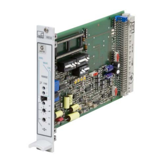
    Europakarten - Messverstärker ME50S6 Europakarten - Messverstärker ME50S6 Die Europakarte ME50S6 ist ein 4,8‐kHz‐Trägerfrequenz Einkanal‐Mess­ verstärker für DMS-Aufnehmer. Die Einschubkarten werden grundsätzlich ohne Gehäuse und ohne Netzteil geliefert, so dass in einer schon vorhandenen 19” Mechanik ein individueller Aufbau möglich ist. Durch die geringe Breite der Einschubkarten (4TE = 20,32 mm) können bis zu 21 Karten in ein 19”‐Gehäuse eingeschoben...
  • Seite 35: Anschlussbelegung

    Abb. 4.1 Brückenanschlussbelegung Die erforderliche Brückenspeisespannung beträgt bei Werkseinstellung 5V (erdsymmetrisch). Über Schalter S25 lässt sie sich auf 1V umschalten. Brückenwiderstand Schalter S25 ≥110...4000 Ω 5 V (Werkseinstellung) ≥60...4000 Ω 1 V (für Betrieb mit SD01) ME50S6 A00260_04_Y00_01 HBM: public...
  • Seite 36: Versorgungsspannung

    ....Kontakt 20a Der Ausgang ist für den Anschluss eines Anzeige‐ und/oder Registriergerätes vorgesehen. Optional ist ein Stromausgang möglich (siehe Kapitel 7.3). ME50S6 A00260_04_Y00_01 HBM: public...
  • Seite 37: Anschlussbelegung, Übersicht

    31c Betriebsspannungsnull (ge) 28a Brückenspeisespannung C (bl) Reihe c Reihe a 29a Betriebsspannungsnull Reihe b : 30a Messsignal D (rt) nicht belegt 31a Betriebsspannungsnull (ge) 32a Brückenspeisespannung B (sw) siehe auch Kapitel 10 „Bauteillageplan“, Seite 24 ME50S6 A00260_04_Y00_01 HBM: public...
  • Seite 38: Bedienen

    Messbereich, möglich. Für MB 1 besteht zusätzlich die Mög­ lichkeit der Feineinstellung über ein externes Potentiometer (siehe Kapitel 6.3). Hinweis Um die werkseitige Einstellung von MB2 (±0,2 mV/V) nicht zu verstimmen, darf P22 nicht verstellt werden (siehe auch Kapitel 6.5). ME50S6 A00260_04_Y00_01 HBM: public...
  • Seite 39 Bedienen ME50 Abb. 5.1 Frontansicht ME50S6 ME50S6 A00260_04_Y00_01 HBM: public...
  • Seite 40: Individuelle Einstellmöglichkeiten

    Eine Voreinstellung der Messbereiche im Bereich ±0,2 mV/V … ±4 mV/V bei = 5 V bzw. ±1 mV/V … ±20 mV/V bei U = 1 V ist mit den DIP‐Schaltern S26 und S27 gemäß Tabelle möglich. Feineinstellung siehe Kapitel 5.3. ME50S6 A00260_04_Y00_01 HBM: public...
  • Seite 41: Externe Messbereichsfeineinstellung Mb1

    Mit einem extern angeschlossenen Potentiometer (5 kΩ) kann eine Mess­ bereichsfeineinstellung durchgeführt werden. Damit sind Korrekturen von ca. 35 %, bezogen auf den eingestellten Messbe­ reich, möglich. Anschlussbelegung: Kontakt 9c R=5 kΩ Kontakt 8c Kontakt 7c ME50S6 A00260_04_Y00_01 HBM: public...
  • Seite 42: Brückennullabgleich

    Kontakt 21c Kontakt 24c Kalibriersignal Der Messverstärker ME50S6 arbeitet in der Sechsleitertechnik, d.h. Kalibriersi­ gnal und Nullkompensationssignal werden aus der rückgeführten Brücken­ speisespannung gebildet und sind somit unabhängig vom Aufnehmer, Anschlusskabel und Kontaktwiderstand. Bei Bedarf lässt sich mit einem inter­...
  • Seite 43: Messfrequenzbereich / Grenzfrequenz Fg

    (Werkseinstellung) 0...40 Hz (-1 dB); Synchronisierung Werden mehrere Messverstärker ME50S6 gemeinsam (im gleichen Gehäuse) betrieben, so ist einer davon als Master zu schalten, dessen Trägerfrequenz den Takt vorgibt, die übrigen Verstärker sind als Slave zu schalten. Zur Syn­ chronisierung sind die Kontakte 12c und 15c aller Verstärker zu verbinden. Die Auswahl des Master‐Verstärkers erfolgt durch Schalter S28.
  • Seite 44: Optionen

    ....Kontakt 5a Der DC/DC Wandler trennt die interne Betriebsspannungen galvanisch von der Versorgungsspannung Werkseinstellung Mit Modul KM001 bzw. DC‐DC‐Wandler ME50S6 A00260_04_Y00_01 HBM: public...
  • Seite 45: Stromendstufenmodul

    Sicherheitsbarrieren für Ex‐Schutz Zum Betrieb von Aufnehmern in explosionsgefährdeten Bereichen können die Sicherheitsbarrieren SD01A eingesetzt werden. Sie entsprechen den Anforderungen der Schutzart EEx ia IIC nach DIN EN 50 014 und DIN EN 50 020 (siehe Datenblatt). ME50S6 A00260_04_Y00_01 HBM: public...
  • Seite 46: Allgemeine Hinweise

    Besonders beim Einsatz in Produktionsbetrieben mit sehr stark gestörten Versorgungsnetzen sind bestimmte Vorschriften bei der elektrischen Installation zu beachten. Die wichtigsten Punkte sind in einem HBM‐Merkblatt aufgeführt. Eine umfassende Zusammenstellung finden Sie in den Installationsrichtlinien VDI/VDE 3551. In welchem Umfang bestimmte Maß­...
  • Seite 47: Technische Daten

    ±2 (Polarität einstellbar) Feinabgleich, mit Schraubendreherpo­ mV/V ±0,08 tentiometer Messfrequenzbereich Butterworth‐Tiefpaß 3.Ordnung, umschaltbar bei ‐1 dB 0...40 0 ... 250 bei ‐3 dB Phasenlaufzeit Anstiegszeit Überschwingen bei Signalsprung <10 <10 Trägerrestspannung <0,02 <0,2; typ. 0,1 ME50S6 A00260_04_Y00_01 HBM: public...
  • Seite 48 (4x350 Ω) im Messbereich 0,2 mV/V bei <13; zusätzlich <0,05% des Brü­ =5 V ckenabgleichwertes Langzeitdrift über 48h (nach 1h Ein­ μV/V <0,05 laufzeit) Einzelbetrieb Verstärkereinschub ME50S6 Stabilisierte Spannung ±15 zum Betrieb von Zusatzeinheiten maximale Stromentnahme <50 Stromversorgung Standard; KM001 DC‐DC‐...
  • Seite 49 < 0,1 "20 bzw. +4...+20 Ausgangsstrom, eingeprägt mit Option EM002 Ω zul. Anschlusswiderstand 0...500 Innenwiderstand kΩ > 100 Stromaufnahme < ± 30 bei Standard und KM001 zusätz­ lich bei DC‐DC‐Wandler 75...25 Linearitätsabweichung bezogen auf < 0,05 Nennstrom ME50S6 A00260_04_Y00_01 HBM: public...
  • Seite 50: Bauteillageplan

    Kalibrieren - Messen - Null S22/23: Null‐Abgleich (grob) S24/1+2: MB1 Feinabgleich intern/extern S24/3: Umschaltung Messfrequenzbereich 40 Hz auf 250 Hz S24/4: MB‐Umschaltung von MB1 auf MB2 S25: Ändern der Brückenspeisespannung S26/27: MB‐Einstellung (grob) P21/22: MB‐Feinabgleich P23: Null‐Abgleich (fein) ME50S6 A00260_04_Y00_01 HBM: public...
  • Seite 51 Operating Manual | Bedienungsanleitung | Manuel d'emploi English Deutsch Français ME50S6...
  • Seite 52 ......Cartes Euro - Amplificateur ME50S6 ......
  • Seite 53 ....... Plan de la disposition des composants ..... ME50S6 A00260_04_Y00_01 HBM: public...
  • Seite 54: Consignes De Sécurité

    350 V (C.A.). Utilisation conforme Le ME50S6 et les capteurs qui lui ont été raccordés doivent être uniquement utilisés pour des tâches de mesure et les opérations de commande qui y sont directement liées. Toute autre utilisation est considérée comme non conforme.
  • Seite 55 Dangers résiduels Les performances du ME50S6 et l'étendue de la livraison ne couvrent qu'une partie des techniques de mesure. La sécurité dans ce domaine doit également être conçue, mise en œuvre et prise en charge par l'ingénieur/le constructeur/ l'opérateur de manière à...
  • Seite 56 Les travaux d'entretien et de réparation sur l'appareil ouvert sous tension sont réservés à une personne qualifiée ayant connaissance du risque existant. ME50S6 A00260_04_Y00_01 HBM: public...
  • Seite 57: Marquages Utilisés

    Conseil Ce marquage signale que des informations concernant le produit ou sa manipulation sont Information fournies. Mise en valeur Pour mettre en valeur certains mots du texte, Voir … ces derniers sont écrits en italique. ME50S6 A00260_04_Y00_01 HBM: public...
  • Seite 58: Marquages Utilisés Sur Le Produit

    être séparés des déchets ménagers pour l'élimination. Pour obtenir plus d'informations sur l'élimination des déchets, veuillez vous adresser aux autorités locales ou au revendeur auquel vous avez acheté le produit. ME50S6 A00260_04_Y00_01 HBM: public...
  • Seite 59: Cartes Euro - Amplificateur Me50S6

    Cartes Euro - Amplificateur ME50S6 Cartes Euro - Amplificateur ME50S6 La carte Euro ME50S6 est un monovoie amplificateur de mesure à fréquence porteuse de 4,8 kHz pour les capteurs à jauges. Les cartes enfichables sont livrées, d'une manière générale, sans boîtier ni bloc d'alimentation, afin de permettre un montage individuel en présence d'une...
  • Seite 60: Code De Raccordement

    Le commutateur S25 permet de la faire pas­ ser à 1V. Résistance du pont Commutateur S25 ≥110...4000 Ω 5 V (réglages d'usine) ≥60...4000 Ω 1 V (pour fonctionnement avec SD01) ME50S6 A00260_04_Y00_01 HBM: public...
  • Seite 61: Tension D'alimentation

    Zéro de la tension de fonctionnement ..Contact 20a Cette sortie a été prévue pour le raccordement d'un afficheur ou d'un appareil enregistreur. Une sortie de courant est possible en option (voir chapitre 7.3). ME50S6 A00260_04_Y00_01 HBM: public...
  • Seite 62: Code De Raccordement, Présentation

    30a signal de mesure D (rg) 31a zéro de la tension de fonctionnement (ve) Ligne c Ligne a 32a tension d'alimentation du pont B Ligne b : (no) non définie Voir chapitre 10 “Plan de la disposition des composants”, page 25 ME50S6 A00260_04_Y00_01 HBM: public...
  • Seite 63: Commande

    MS 1 (voir chapi­ tre 6.3). Note Pour ne pas déséquilibrer le réglage d'usine de MS2 (±0,2 mV/V), le réglage de P22 ne doit pas être modifié (voir aussi chapitre 6.5). ME50S6 A00260_04_Y00_01 HBM: public...
  • Seite 64 Commande ME50 Fig. 5.1 Vue de face du ME50S6 ME50S6 A00260_04_Y00_01 HBM: public...
  • Seite 65: Possibilités De Réglages Individuels

    DIP S24/4 ou une commutation externe permet d'activer l'étendue de mesure 2. Etendue de mesure S 24/4 Externe MR 1 = ±1 mV/V (réglage d'usine) de MR1 à MR2; MR 2 = ±0.2 mV/V relier 25c & 15c ME50S6 A00260_04_Y00_01 HBM: public...
  • Seite 66: Réglage Externe De Précision L'étendue De Mesure Ms1

    Un potentiomètre externe raccordé (5 kΩ) permet de réaliser un réglage de précision de l'étendue de mesure. Des corrections d'env. 35 %, par rapport à l'étendue de mesure réglée sont ainsi possibles. Code de raccordement : Contact 9c R=5 kΩ Contact 8c Contact 7c ME50S6 A00260_04_Y00_01 HBM: public...
  • Seite 67: Equilibrage Du Pont

    Contact 24c Signal de calibrage L'amplificateur de mesure ME50S6 fonctionne en technique 6 fils. Cela signifie que le signal de calibrage et le signal de compensation du zéro sont issus de la tension d'alimentation du pont de contre‐réaction et qu'ils ne dépendent donc ni du capteur, ni du câble de raccordement ni de la résistance de contact.
  • Seite 68: Bande Passante / Fréquence De Coupure Fg

    Synchronisation Lors de l'utilisation simultanée (dans un même boîtier) de plusieurs amplifica­ teurs de mesure ME50S6, l'un d'entre eux doit être mis en circuit en tant que maître, dont la fréquence porteuse prédéfinit la cadence. Les autres amplifica­ teurs doivent être mis en circuit en tant qu'esclaves. Pour la synchronisation, il convient de relier les contacts 12c et 15c de tous les amplificateurs.
  • Seite 69: Options

    ......Contact 5a Le convertisseur C.C.-C.C. sépare galvaniquement les tensions de fonctionne­ ment interne de l'alimentation. Réglage d'usine Avec module KM001 ou convertisseur C.C.-C.C. ME50S6 A00260_04_Y00_01 HBM: public...
  • Seite 70: Module D'étage De Sortie Courant

    Des barrières de sécurité SD01A peuvent être utilisées, en vue de l'utilisation de capteurs en atmosphère explosible. Elles sont conformes aux exigences de l'indice de protection EEx ia IIC selon DIN EN 50 014 et DIN EN 50 020 (voir fiche technique). ME50S6 A00260_04_Y00_01 HBM: public...
  • Seite 71: Remarques Générales

    électriques fortement parasités, il convient de tenir compte de certaines réglementations au niveau de l'installation électrique. Une feuille d'information HBM liste les points essentiels. Un récapitulatif complet est disponible dans les directives d'installation VDI/VDE 3551. La mesure dans laquelle certaines mesures doivent être appliquées dépend des conditions locales d'utilisation.
  • Seite 72: Caractéristiques Techniques

    Équilibrage fin, avec potentiomètre à mV/V ±0,08 tournevis Bande passante Passe-bas Butterworth d'ordre 3, commutable pour -1 dB 0...40 0...250 pour -3 dB Retard de phase Temps de montée Dépassement sur saut de signal <10 <10 ME50S6 A00260_04_Y00_01 HBM: public...
  • Seite 73 =5 V la valeur d'équilibrage de pont μV/V Dérive à long terme sur 48 h (après <0,05 1 h de temps de chauffe) Fonctionnement individuel d'un module amplificateur ME50S6 Tension stabilisée pour l'utilisation d'unités complémen­ ±15 taires prélèsement de courant maxi <50...
  • Seite 74 Option EM002 Ω résistance de raccordement admissible 0...500 résistance interne kΩ >100 consommation de courant avec standard et KM001 <±30 additionnel avec convertisseur C.C. 75...25 Ecart de linéarité par rapport à la < 0,05 tension nominale ME50S6 A00260_04_Y00_01 HBM: public...
  • Seite 75: Plan De La Disposition Des Composants

    S24/4 : Commutation de MS de MS1 à MS2 S25 : Changement de la tension d'alimentation du pont S26/27 : Réglage (grossier) de MS P21/22 : Ajustement fin de MS P23 : Mise à zéro (fine) ME50S6 A00260_04_Y00_01 HBM: public...
  • Seite 76 HBM Test and Measurement Tel. +49 6151 803-0 Fax +49 6151 803-9100 info@hbm.com measure and predict with confidence...

Inhaltsverzeichnis