HBM PMX Bedienungsanleitung

Verwandte Anleitungen für HBM PMX


Inhaltszusammenfassung für HBM PMX
- Seite 1 Operating manual Bedienungsanleitung Manuel d’emploi Measuring amplifier system Messverstärkersystem Système amplificateur de mesure A3257−2.0 en/de/fr...
-
Seite 3: Inhaltsverzeichnis
........3.2 About the PMX documentation . - Seite 4 ....... . 9.3 Connect the PMX with a PC (HOST) or via a network .
- Seite 5 ....... 11.4 Output data, control (PLC) −> PMX ......
-
Seite 6: Safety Instructions
10 to 30 V. General dangers of failing to follow the safety instructions The PMX system is a state of the art unit and as such is reliable. The module may give rise to residual dangers if it is inappropriately installed and operated by untrained personnel. - Seite 7 − Install the device so that it can be disconnected from the mains at any time without difficulty. − It is safe to operate the PMX system up to a height of 2000 m. Maintenance and cleaning The PMX system is maintenance-free.
- Seite 8 Safety instructions The safety instructions take the following form: SIGNAL WORD Type of danger Consequences of non-compliance Averting the danger − Warning sign: draws attention to the danger − Signal word: indicates the severity of the danger (see table below) −...
- Seite 9 In particular, any repair or soldering work on motherboards is prohibited. When exchanging complete modules, use only original parts from HBM. The product is delivered from the factory with a fixed hardware and software configuration.
- Seite 10 It is also essential to comply with the legal and safety requirements for the application concerned during use. The same applies to the use of accessories. The PMX system must only be installed by qualified personnel, strictly in accordance with the specifications and with the safety requirements and regulations listed below.
-
Seite 11: Pmx Product Description
ETHERNET interface, and can be parameterized and operated via the internal web server. The link to an automation system can be connected via digital and analog in- puts/outputs, as well as over the fieldbus interfaces of the PMX, to a control (PLC) or a primary automation system. Internal computing channels The PMX has 32 internal computing channels as standard, which are freely available for evaluations and mathematical measurement signal calculations. - Seite 12 PMX web server An easy to operate web server that is specifically tailored to the PMX and is suitable for the measurement cards, is integrated into the device for configura- tion, data acquisition and visualization.
- Seite 13 Product description catman The HBM catman software can be used to acquire, condition and analyze the PMX measurement data, as an option. This allows vast quantities of measurement data to be displayed (stripchart function) and analyzed. A3257−2.0 en/de/fr...
-
Seite 14: User Information
Make sure that all the documents you possess and use are always the current version. The current documentation version for your HBM products can be found at http://www.hbm.com/hbmdoc 3.1 Using this manual Read this operating manual thoroughly and in full before operating the equipment for the first time. -
Seite 15: About The Pmx Documentation
You can find additional information at http://www.hbm.com/support regarding e.g. device description files for the realtime Ethernet cards (Profinet/ EtherCat) and configuration examples. You can find additional information at http://www.hbm.com/pmx, as well as a PMX video tutorial. A3257−2.0 en/de/fr... -
Seite 16: Symbols Used In This Manual
The CE mark enables the manufacturer to guarantee that the product complies with the requirements of the relevant EC directives (the Declaration of Conformity can be found at http://www.hbm.com/HBMdoc). Statutory waste disposal mark see Chapter 8, Waste disposal Statutory mark of compliance with emission limits in... -
Seite 17: Technical Support
User information 3.3 Technical support Should you have any questions when working with the PMX measuring ampli- fier system, HBM’s technical support can provide: E-mail support info@hbm.com Extended support can be obtained through a maintenance contract. Fax support 06151 803 288 (within Germany) -
Seite 18: Model Overview, Scope Of Supply And Accessories
Model overview, scope of supply and accessories 4.1 The PMX system The PMX system is a modular and universally applicable measuring amplifier system. The measurement cards, input/output cards and communication cards can be individually combined and intelligently configured, in accordance with the measurement task. - Seite 19 Model overview Communication cards Module Description Order no. 1) PX01EC EtherCAT module 1−PX01EC PX01PN PROFINET-IO module 1−PX01PN Overview of measurement cards and the input/output card : Measurement card Input/output card Measurand PX401 PX455 PX878 SG full bridge SG half bridge Inductive full bridge Inductive half bridge LVDT...
-
Seite 20: Scope Of Supply
Model overview 4.2 Scope of supply Order no. 1 PMX basic device, with a wall mounting kit (1 wall bracket, 4 screws, 4 washers) with CAN connection 1−WGX001 without CAN connection 1−WGX002 For each measurement card : a mating connector for each channel (4 connectors are enclosed for each measurement card, complete with 1−CON−S1008... - Seite 21 Model overview Important You have the option to retrofit or subsequently remove measurement cards, I/O cards and communication cards. A3257−2.0 en/de/fr...
-
Seite 22: Pmx Web Server/Software
Model overview 4.4 PMX web server/software A PMX web server, including Help, is integrated in the device. The web server also has a firmware loader function, which can transfer new PMX firmware and web server versions to the PMX. An online Help is integrated into the web server to support PMX operation and handling. - Seite 23 Model overview A3257−2.0 en/de/fr...
-
Seite 24: Degree Of Protection / Housing / Shielding Design
These indicate which degree of protection a housing offers against contact or foreign bodies (first digit) and moisture (second digit). All PMX modules and the basic device are designed with degree of protection IP20 (as per DIN EN 60529). - Seite 25 Degree of protection NOTE Use standard HBM cables for connecting the transducers. When using other shielded, low-capacitance measurement cables, attach the shield of the trans- ducer cable to the ground connection provided on the multipoint connector, in accordance with HBM Greenline information (www.hbm.com/green- line).
-
Seite 26: Mounting/Dismounting/Replacing
Mounting Mounting/Dismounting/Replacing 6.1 Support rail mounting Allen screw 3 mm Fig. 6.1: Mounting on a support rail Undo the four back-panel screws (cross-recess M3x8) (1) Slide the side panels forward (2) Screw on the support rail mounting (3) (approx. 5 Nm), in a choice of four positions (two positions for the 7.5 mm support rail), see Fig. - Seite 27 Fig. 6.2: Four positional options for support rail mounting Important HBM recommends using a DIN support rail (DIN EN 60715), 15 mm in height. When using a smaller support rail (7.5 mm high), it should be packed, to make it easy to hook/unhook the PMX device.
- Seite 28 To ensure adequate grounding for the PMX, the support rail must be connected to grounded conductor potential Both the DIN rail and the PMX must be free of paint, varnish and dirt at the point of installation. Dimensions and mounting instructions...
-
Seite 29: Wall Mounting
Mounting 6.2 Wall mounting Fig. 6.3: Mounting on a wall Attach the wall bracket at the back of the PMX with the enclosed M4 screws (1) A3257−2.0 en/de/fr... - Seite 30 Screw the complete unit to a wall; hole Ø 4 mm NOTE The housing must also be connected to grounding conductor potential in a wall mounting. Connect the PMX housing to ground via the grounding screw. Dimensions and mounting instructions min. 25 Minimum dimension : Connector plus sensor cable...
-
Seite 31: Replacing Measurement And Communication Cards
If the measurement or communication cards are incorrectly removed/re- placed, they may be damaged or destroyed. These cards must be de-energized before they are removed or replaced Always disconnect the PMX from the power supply before removing a card. The instructions below must also be followed: Removal: 1. - Seite 32 Mounting Installation: 1. Carefully insert the board into the PMX slot 2. The board centers itself in the VG strip at the back 3. Re-tighten the three M2.5 screws NOTE Close the open module slots with blanking plates. A3257−2.0 en/de/fr...
-
Seite 33: Electrical Connections
Electrical connection Electrical connections Important The grounding terminal on the PMX is not a protective ground (optional connection). The measurement system is fitted with an automatic current limiter for each device card, as well as for the PMX basic device. -
Seite 34: Electrical Connection
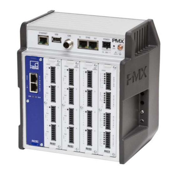
Electrical connection 7.1 Overview of PMX functions Measurement cards (PX401, PX455) and/or Ethernet plug for PC/network connection PX878 I/O card or blanking plate USB host, e.g. for a memory stick Measurement card LEDs Communication cards: CAN for CAN driver, M12, option (WG001) ... -
Seite 35: Combination Options
Electrical connection Combination options Slot Slot Slot Slot Slot Number of Plug-ins Fieldbus − − − − 0 − 1 or blan- king plate PX401 − 0 − 4 PX455 − 0 − 4 PX878 − − − 0 − 2 Relevance of the basic device connection sockets (WG001): Á... - Seite 36 Electrical connection Synchronization of several (max. 20) PMX devices via two RJ45 sockets. See Section 8.1 − (view of device front) Supplying voltage to the PMX by connecting a separate DC voltage supply. CAN connection (type WG001 only). Signal Description...
-
Seite 37: Leds For System Monitoring (Device Led)
Electrical connection 7.1.1 LEDs for system monitoring (device LED) Basic device (WGX001/002) : Á ETHERNET LED Status Significance Ethernet Link (1) Steady Link is available green Ethernet RX / TX (2) Flashing Data are being transmitted yellow SYNC IN / OUT (3, 4 and 5, 6) Status Significance... -
Seite 38: Fieldbus Led
Electrical connection SYS LED (7): Status Significance Voltage supply available green Voltage supply missing Device is booting yellow Flashing Serious internal error Firmware update ongoing 7.1.2 Fieldbus LED PX01EC EtherCAT Status Significance no error Flashing Configuration error Single flash Synchronization error Double flash Application timeout error... - Seite 39 Electrical connection Status Significance INIT status green Flashing PRE OPERATIONAL status green Single flash SAFE OPERATIONAL status green green OPERATIONAL Status Significance Permanently on Connection established Flashing Send / Receive green No connection − No function − A3257−2.0 en/de/fr...
- Seite 40 Electrical connection PX01PN Port 2 Port 1 PROFINET Status Significance System error, incorrect configura- tion Flashing Flashing for device detection is controlled by the IO controller No connection or no configuration Flashing Bus error, incorrect configuration, not all IO devices are connected Status Significance Permanently on...
-
Seite 41: Measurement Card Leds
Electrical connection 7.1.3 Measurement card LEDs PX401, channel status Status LED Status Significance no errors green Flashing Firmware update yellow Parameter not OK, overloaded PX455, channel status Status LED Status Significance no errors green No transducer connected or wire break yellow (calibration ongoing) Flashing... - Seite 42 Electrical connection PX878 status-LED channel Status Significance Digital Digital output : High green Digital output : Low Digital input : High green Digital input : Low Analog Analog output configured green Analog output is not configured Analog output overloaded, signal invalid A3257−2.0 en/de/fr...
-
Seite 43: Supply Voltage
7.2 Supply voltage With a separate DC voltage power supply (10 to 30 V DC, nom. 24 V, power output at least 20 W), the PMX device is supplied with voltage via the POWER socket (1) (see Chapter 9 “Starting up ”... -
Seite 44: Measurement Cards / Transducer Connection
’ Sense lead (+) Sense lead (−) ’ Cable color code for HBM transducer cables: wh= white; bk= black; bu= blue; rd= red; ye = yellow; gn= green; gy= gray Hsg.= housing Fig. 7.1: PX455 plug terminal pin assignment A3257−2.0 en/de/fr... - Seite 45 Electrical connection Potentiometric transducers Measurement signal (+) Bridge excitation voltage (−) Bridge excitation voltage (+) Cable shield Hsg. Sense lead (+) Sense lead (−) Cable color code: wh= white; bk= black; bu= blue; rd= red; ye = yellow; gn= green; gy= gray Fig.
-
Seite 46: Px401
Electrical connection 7.3.2 PX401 Current/voltage sources 1-wire TEDS see Section 7.6.3 TEDS module TEDS Supply for OUT + external OUT − transducers Cable Housing shield " Fig. 7.4: PX401 plug terminal pin assignment : voltage source 10 V A3257−2.0 en/de/fr... - Seite 47 The individual measurement channels on the PX401 measurement card are not electrically isolated from each other. The PX401 measurement card has electrical isolation from the basic device mains. The power supply for external transducers is not electrically isolated and corresponds to the PMX device’s power supply. A3257−2.0 en/de/fr...
- Seite 48 Electrical connection WGX basic device PX401 housing Channel 1 Channel 4 Electrical isolation from mains Fig. 7.6: Electrical isolation from mains PX401 A3257−2.0 en/de/fr...
-
Seite 49: Input/Output Cards
Electrical connection 7.4 Input/output cards 7.4.1 PX878 Analog outputs, digital inputs/outputs Terminal 1 Analog output Terminal 2 Digital input/output Terminal 3 Digital output Terminal 4 Digital input Analog Out 1 Analog Out 2 Analog Out 3 Analog Out 4 Analog Out 5 Analog GND Cable shield Fig. - Seite 50 Digital Out 4 Digital Out 5 Digital Out 6 Digital Out 7 Digital Out 8 Cable shield Fig. 7.8: Digital input and digital output pin assignment (terminals 2 and 3) The PMX voltage supply socket (POWER) supplies the power A3257−2.0 en/de/fr...
- Seite 51 IN 6 IN 7 IN 8 Cable shield Digital input/output terminal Fig. 7.9: Digital input pin assignment (terminal 4) Important The functions of the control inputs/outputs and the analog outputs can be assigned via the PMX web server. A3257−2.0 en/de/fr...
-
Seite 52: External Supply Voltage For Control Inputs (Px878)
The control outputs are available at the Digital OUT 1 and OUT 2 terminals, as well as the OUT 3 to OUT 8 terminals. They are electrically isolated from the PMX housing, but not from each other (see Fig. 7.11). A3257−2.0 en/de/fr... - Seite 53 The control inputs are available at the Digital IN 1 and IN 2 terminals, as well as the IN 3 to IN 8 terminals. They are electrically isolated from the PMX housing, but not from each other (see Fig. 7.11).
- Seite 54 Electrical connection PX878 housing Analog OUT Electrical isolation from mains Digital OUT 1 . . 1 . . Fig. 7.11: Electrical isolation from mains PX878 A3257−2.0 en/de/fr...
-
Seite 55: Communication Cards
Electrical connection 7.5 Communication cards 7.5.1 Port assignment for the PX01EC EtherCAT fieldbus module EtherCAT master or EtherCAT slave devices Fig. 7.12: EtherCAT connection as per standard 7.5.2 Port assignment for the PX01PN PROFINET−IO fieldbus module Port 2 PROFINET devices or PROFINET master or... -
Seite 56: Teds Transducers
TEDS stands for “Transducer Electronic Data Sheet”. Transducers with an electronic data sheet as defined in the IEEE 1451.4 standard can be connec- ted to the PMX system, making it possible for the amplifier to be set up auto- matically. A suitably equipped amplifier imports the transducer characteristics (electronic data sheet), translates them into its own settings and measure- ment can then start. -
Seite 57: Pmx Parameterization With Teds
In the PX401 measurement card, the TEDS chip is addressed separately, via an additional connection (1-wire TEDS). When the PMX is switched on, it automatically detects whether a sensor with TEDS is connected. Die Daten werden ausgelesen und der Verstärkerkanal damit parametriert. -
Seite 58: Synchronization
Synchronization Synchronization 8.1 Synchronizing carrier frequencies and time stamps When PMX devices are connected, the carrier frequency and the time stamp can be synchronized via the SYNC socket. The status can be read from the LED. The master/slave allocation is automatic. -
Seite 59: Synchronizing Several Modules
(always identical to the right-hand LED of green yellow the IN socket) 8.2 Synchronizing several modules Master Master Á Á Á Á Á Á Á Á Á Á Á Á RJ45 cable Fig. 8.1: Connecting several PMX modules A3257−2.0 en/de/fr... - Seite 60 Synchronization Synchronizing measured values and carrier frequency Up to 20 PMX devices can be connected via the SYNC socket. One PMX device is automatically declared the master. Recommended cable: Standard Ethernet Cat−5−S/FTP. 1:1 This cable takes care of carrier frequency and time stamp synchronization.
-
Seite 61: Starting Up
− The bus does not need any termination resistors, as active nodes are involved. The device description file (GSDXML) is available for configuring the PMX in the master. This is on the PMX System CD or is available as a download from www.hbm.com/support... -
Seite 62: Ethercat Connection
− The bus does not need any termination resistors, as active nodes are involved. The device description file (HBM PMX XML) is available for configuring the PMX in the master. This is on the PMX System CD or is available as a download from www.hbm.com/support... - Seite 63 Starting up Example with a Beckhoff PLC with the TwinCAT System Manager A3257−2.0 en/de/fr...
-
Seite 64: Integrated Pmx Web Server
9.2 Integrated PMX web server 9.2.1 System requirements To operate current versions of the PMX devices, you need a terminal (e.g. PC / tablet with a mouse) with a common Internet browser (Internet-Explorer (Ver- sion > 9.0), Firefox or Chrome) and a screen resolution of 1024 x 768. -
Seite 65: Connect The Pmx With A Pc (Host) Or Via A Network
− DHCP (automatic address assignment as per RFC2131 and RFC2132) − from the Apipa auto IP range (RFC5735) in the range 169.254.xxx.xxx The device name set at the factory for the PMX is “pmx”, but this can be changed. - Seite 66 Connection via Universal Plug & Play, from the Windows 7 version This connection depends on the network settings and is also possible without DHCP and in the auto IP range*). Not available in a PMX − PC connection (without a network), and not in public networks. Open the network −...
- Seite 67 Starting up If several PMX devices are available in the network, this selection box will also appear: Check the box for the required PMX Click Setup A3257−2.0 en/de/fr...
- Seite 68 Starting up This takes you to the device overview: Now you can measure, make settings and observe. A3257−2.0 en/de/fr...
- Seite 69 Connection via the NetBIOS name under Windows “PMX” appears in the network environment Enter “pmx/” (without “ ” but with /) in the address bar of an Internet browser Assigning names if there are several PMX devices in the network: ...
- Seite 70 Now you can measure, make settings and observe. Important If a DHCP server cannot be found, the PMX device (as per RFC5735 Apipa) automatically assigns its own IP address (169.254.xxx.xxx/16). Requirement : There is no static IP address entered in the PMX device! If a static IP address has been set, there will be 2 IP addresses available: the set static address and an IO address from the automatic IP range.
- Seite 71 Enter pmx.local. in the address bar of an Internet browser Now you can measure, make settings and observe. Important The device name (“pmx” from the factory) and the network settings (DHCP, IP address, netmask, gateway) can be permanently changed by the user (Network menu item).
-
Seite 72: Restoring Lost Network Settings
4. Plug the USB stick into the PMX device while operation is ongoing. The settings will change immediately, but will not be immediately apparent in the other network devices. So it is a good idea to to restart the PMX by inter- rupting the power supply. - Seite 73 Starting up Change the network settings: Overview Settings. System Device Network settings A3257−2.0 en/de/fr...
-
Seite 74: Display And Control Options
The LED at the bottom left shows the status of the PMX: Everything OK. There is an error in one or more of the channels, but the PMX keeps on working. There is a critical error, measured values can no longer be recorded or processed. - Seite 75 The small graphic in the status bar at the bottom ( ) shows the util- ization of the PMX. You can use this to estimate whether the specified calcula- tions can take place at the selected data rate, or whether either the number of calculations has to be reduced, or the data rate decreased.
-
Seite 76: Pmx Web Server Menu Structure
Starting up 9.5 PMX web server menu structure 9.5.1 Overview −> SETTINGS The PMX can be parameterized via SETTINGS. Menus can be selected indi- vidually. Each menu item has an online Help, that is called by clicking on the symbol. -
Seite 77: Pmx Startup Behavior
LED (see Sections 7.1.1 to 7.1.3) − When the PMX is switched on, the digital and analog outputs are set to 0 V. − When the system powers up, the analog outputs are set to 0 V. -
Seite 78: Signal Propagation Delays
Starting up 9.7 Signal propagation delays Typical signal propagation delays of the individual PMX hardware and soft- ware components. Hardware Firmware Hardware Limit PX878 PX878 switch / Dig. input Dig. output dig. output 0.18 ms 0.08 ms < 0.3 ms... - Seite 79 Starting up Filter group delay (ms) Cut-off Delay [ms] frequency fc Bessel Butterworth [Hz] (−3dB) 3000 0.10 0.14 2000 0.20 0.28 1000 0.42 0.61 0.86 1.23 2.00 3.10 4.15 6.17 8.45 12.5 21.4 30.7 1680 2090 3360 4200 Tab. 1.1: Delays for PX401 Cut-off Delay [ms] frequency fc...
- Seite 80 Starting up Data transfer minimum typical maximum rate [ms] [ms] [ms] [Hz] 1200 0.52 0.93 2400 0.31 0.52 (factory default) 4800 0.21 0.31 9600 0.16 0.21 Tab. 1.3: Data delays Example: Signal runtime of a sensor signal via the analog output with filter: Signal path PX455 →...
-
Seite 81: Quick Start
3. Connect the voltage supply (10 … 30 V DC) (see Section 7.2) The PMX boots, and then displays its system status. (see Section 7.1.1). The system LED must show green. This process takes a few seconds. −... - Seite 82 PC (HOST) to DHCP as well. Automatic adjustment and setting of the IP addresses will then follow. This process takes a few seconds. Call the PMX web server by entering “PMX” in the browser bar and press RE- TURN.
- Seite 83 Quick Start If several PMX devices are available in the network, this selection box will also appear: Check the box for the required PMX Click Setup The Flash function allows the device to be identified by flashing all the device LEDs.
- Seite 84 Quick Start Security prompt To get additional help, click the Help symbol This opens the web server Help. A3257−2.0 en/de/fr...
-
Seite 85: Typical Operating Procedure
PMX web browser. The sensors, Ethernet cable and voltage supply must be properly connected (see Sections 7.3 and 7.2). Connect the PMX to a PC (HOST) (see Section 9.3), to see the device over- view. - Seite 86 − The filter type is Bessel, the filter frequency is set to 5 Hz (average to high attenuation). − The data are now changed in the PMX and are displayed by a floppy disk symbol in the status line − Press this symbol to store the settings power failsafe in the PMX (security prompt).
-
Seite 87: Update Software (Pmx Web Server)
> 9.0), Firefox or Chrome) and a screen resolution of min. 1024 x 768. A new version of the web server is a component part of the PMX firmware, and they are installed together, in a firmware update (see Chapter 14). -
Seite 88: Function Blocks For Calculated Channels
Quick Start 10.3 Function blocks for calculated channels The following applies for all function blocks, unless specified otherwise: Calculation rate Equals the data rate (default 19200/s) Range of values of the Single-precision floating point resolution as per IEEE754 floating point values Range approx. - Seite 89 Quick Start Divider (divider) Function Division y = Dividend / Divisor Inputs Inputs dividend, divisor Outputs Quotient out0 Parameters Default dividend: Constant 1.0 divisor: Constant 1.0 Exception handling If one or a number of inputs is marked as invalid (Invalid bit), the output is also marked as invalid.
- Seite 90 Quick Start Frequencies and group delays Low pass fc [Hz] Bessel Butterworth Delay [ms] Delay [ms] 3000 0.13 0.19 2000 0.21 0.30 1000 0.43 0.61 0.86 1.23 2.00 3.10 4.15 6.17 8.45 12.5 21.4 30.7 1680 2090 3360 4200 High pass fc [Hz] Bessel Butterworth...
- Seite 91 Quick Start Signal generator (signalGen) Function Generates a periodic signal Inputs Outputs Generated signal out0 Parameters - Waveform [sine, square, noise, counter, constant, triangle] - Frequency 0 .. data rate/4 (default 19200/4 Hz = 4800 Hz) (only effective with sine, square, triangle) - Amplitude - Offset Default...
- Seite 92 Quick Start Extreme value (peak) Function Maximum, minimum or peak-to-peak value Reset via digital input (edge-controlled) Hold via digital in- put (level-controlled) Inputs - Input in0 - Digital Reset input - Digital Hold input Outputs Extreme value out0 Parameters - Type [Maximum, Minimum, Peak-to-Peak] - Inverting of the Hold input Default Type: Maximum...
- Seite 93 Quick Start 10 Hold (hold) Function Holds the input value controlled via a digital input Inputs - Input in0 - Digital Hold input (edge-controlled) - Digital Reset input (only effective if post-triggering not possible) Outputs Value on hold out0 Parameters - Inverting of the Hold input (yes/no) Yes: Hold if high ->...
- Seite 94 Quick Start - Lower threshold of capture range threshLow - Capture outside (yes/no), capture outside interval [threshLow, threshHigh] - On entry into interval only (onEntryOnly) (yes/no) Yes: The value is captured on entry into the interval (if necessary, after expiration of delay) and held until the next entry.
- Seite 95 Quick Start 12 Fast tare (fastTare) Function Fast zero or tare, controlled via the digital input. Inputs - Input in0, input with untared original measured value - Tare value (tareValue), input with the value that is ap- plied to the output on tare. Tare value = 0 corresponds to zero.
- Seite 96 Quick Start 13 Two-Level Controller (bangbang) Function Bang-bang control with feedback Inputs - Input in0 setpoint value (setpoint) - Input in1 actual value (feedback) Outputs Digital output out0, (Digital Outputs menu, ”Calculated Channel Bit Mask”) Parameters - Hysteresis - Feedback gain (Kr) Common gain of both parallel PT1 feedback paths - Feedback time constant 1 (Tr1 ) [seconds] PT1 time constant of the negative feedback path...
- Seite 97 Quick Start 14 PID controller (pid) Function Quasi linearer PID controller with parallel structure and anti-windup Kp (1+ 1 Td * s Ti * s Tp * s +1 Tp is the parasitic time constant, see below. Inputs - Input in0 setpoint value (setpoint) - Input in1 actual value (feedback) - Digital Enable input (enableId) Outputs...
- Seite 98 Quick Start 15 4th order polynomial (polynomial4) Function 4th order polynomial y = a0 + a1*x + a2*x + a3*x + a4*x Inputs Input in0 (x) Outputs Output out0 (y) Parameters a0, a1, a2, a3, a4 Default in0: Constant 0.0 a0, a1, a2, a3, a4: 0.0 Exception handling If the input is marked as invalid (Invalid bit), the output is...
- Seite 99 Quick Start 17 Pulse Width (time span) Function Measures the time span between two edges on digital in- puts. The duration of a periodic signal can also be measured. It is output in ms, s or as a frequency 1/s. Time resolution: Equals 1/ calculation rate (see above), Default 1/19200 = 52 s Maximum time that can be measured: 1/calculation rate *...
- Seite 100 Quick Start Measurement uncertainty related to the measured value With data rate 19200/s Pulse/Period dura- ... corresponds to Uncertainty tion frequency [ms] [1/s] 1000 5.21 2.60 1.04 0.52 0.26 0.10 0.05 0.03 0.01 1000 0.01 A3257−2.0 en/de/fr...
-
Seite 101: Communication With A Control System
This is needed to parameterize the master and create the automation program. The device description files are on the PMX system CD (included among the items supplied) or can be downloaded from hbm.com −> Support−> Software and firmware downloads. -
Seite 102: Input Data, Pmx −> Control (Plc)
Communication 11.3 Input data, PMX −> control (PLC) 11.3.1 Device data (cyclic) Function PROFINET Data EtherCAT slot.subslot type index System status see below 6000.1 uint32 bytes 0..3 Parameter set Currently active parameter 6000.2 int32 bytes 4..7 GUI status - not in use - 6000.3... -
Seite 103: Measured Values (Cyclic)
Communication 11.3.3 Measured values (cyclic) Function PROFINET Data EtherCAT slot.subsl type index Flags Status flags from 6001.1 uint32 calculated channels; not bytes 0..3 currently assigned Flags status always 0 6001.2 uint8 byte 4 Flags control ‘Flags control word’ 6001.3 uint8 word return 7001.1... -
Seite 104: Measured Value Status
Communication Note on calculated channels: In the PMX device, the calculated channels are assigned to virtual slot 9. For technical reasons, 9 cannot be the third digit in the EtherCAT indexes. Calculated channels currently appear in indexes 6051 to 60b4. -
Seite 105: Output Data, Control (Plc) −> Pmx
Communication 11.4 Output data, control (PLC) −> PMX 11.4.1 Device data (cyclic) Function PROFINET Data EtherCAT slot.subslot type index Device Bit 0: LEDs flash for 30 s 7000.1 uint32 control word bytes 0..3 Parameter set Range 0..999 7000.2 uint32 request bytes 4..7... -
Seite 106: Measured Value Control Words (Cyclic)
Note on calculated channels: In the PMX device, the calculated channels are assigned to virtual slot 9. For technical reasons, 9 cannot be the third digit in the EtherCAT indexes. -
Seite 107: Profinet
PROFINET configuration tool and set via the PROFINET cable. These data can be read for checking in the “Fieldbus” dialog of the PMX user interface. − The PROFINET configuration must match the installed PMX cards. Example Slot 1... -
Seite 108: Ethercat
The EtherCAT Master configuration must match the installed cards. Calculated channels: The number must match the PMX setting (Fieldbus menu). The calculated channels are distributed in the EtherCAT Master to virtual “Calculated Channels” slots. The distribution across the slots does not play a role, but the total number of the channels must match. -
Seite 109: Pmx Command Set (Api)
The TELNET protocol running under Windows offers a easy way to use PMX commands. The IP addresses of the PMX and the PC (HOST) must match and the devices have to be connected via Ethernet (if necessary, assign the PMX a matching IP address with DHCP as default setting). - Seite 110 Example: PMX command list in a Telnet session under Microsoft Win- dows The PMX has to be connected to the PC (HOST) via an Ethernet cable or Eth- ernet network. Identify the IP address of the PMX either by directly assigning an address or in the PMX web browser’s ”Network”...
-
Seite 111: Comand List
AMT? Amplifier Type Query Output the amplifier type Syntax: AMT?(x) Parameter: none Response: q1(y) Amplifier type 5120 PMX , 1st version, no CAN 5125 PX401 5126 PX455 5127 PX878 5129 Channel (Slot) 10, digital IOs A3257−2.0 en/de/fr... - Seite 112 Commmands Programming Channel Select Channel selection for setup commands This command performs channel selection for the immediately following setup commands. Syntax: PCS p1,.., p16 (x) Parameter: p1,.., p16 channels PCS 0 (x) selects all the existing channels Initially all channels (boards) are selected. If one channel (board or slot) is not available, this channel will be ignored and will not be added to the list PCS(x) clears all selected channels(boards/slots).
- Seite 113 Parameter: p1: any string ”_____”, max. 45 characters Note: The HBM setup Assistant for the MGCplus distinguishes between a channel name and comment which are both stored in the UCC string. The channel name and comment are sep- arated by a “;”...
- Seite 114 ”__(String)__”(y): stored string, with a “ at the beginning and the end Note: The HBM setup Assistant for the MGCplus distinguishes bet ween a channel name and comment which are both stored in the UCC string. The channel name and comment are separated by a “;”...
- Seite 115 Commands EUN? Engineering Unit Query Output of physical unit Syntax 1: EUN?(x) Parameter: none Response: q1(y): ”UnitString” Syntax 2: EUN??(x) Parameter: none Response: q1(y): Unit-Code Supported units: Code Name ASCII name // Angle(radians) ”rad” ”” ”radian” ”” ” ” ”deg” ”%degrees”...
- Seite 116 Commmands ”A” ”uA” ”mA rms” ”” ”A rms” ”uA rms” // Temperatur e ”K” ”” ” C” ”degC” ” F” ”degF” ” Rank” ”degRank” ” R” ”degR” // Voltage/Sensitivity 1000 ”V/V” ”” 1001 ”mV/V” ”” 1002 ”V/V” ”uV/V” // Voltage 1100 ”V”...
- Seite 117 Commands // Rot. speed 1700 ”radian/s” ”” 1701 ”U/min” ”” 1702 ”rpm” ”” // Power m kg s A K mol cd 1800 ”W” ”” 1801 ”mW” ”” 1802 ”kW” ”” 1803 ”MW” ”” // Force 1900 ”N” ”” 1901 ”kN”...
- Seite 118 Commmands // Speed 2400 ”m/s” ”” 2401 ”km/h” ”” 2402 ”mph” ”” 2403 ”fps” ”” // Acceleration 2500 ”m/s ” ”m/s2” 2501 ”ga” ”” // Density 2700 ”kg/m ” ”kg/m3” 2701 ”g/l” ”” // Flow 2800 ”m /s” ”m3/s” 2801 ”l/min”...
- Seite 119 Commands 5007 ”kg/s” ”” 5008 ”mole/l” ”” 5009 ”mole/m ” ”mole/m3” 5010 ”N/m” ”” 5011 ”RH” ”” 5012 ”V/(m/s )” ”V(m/s2)” 5013 ”V/C” ”” 5014 ”V/N” ”” 5015 ”V/Pa” ”” 5016 ”W/ C” ”W/degC” 100000 ”UserDefined” ”usr” Read status register Standard Event Status Register Output the error status register Syntax: ESR? (x)
- Seite 120 Commmands Bit: 7 6 5 Device Dependent Error: Geräteabhängiger Fehler, z.B. Befehl bei diesem Verstärker nicht erlaubt Execution Error: Parameter-Fehler, z.B. zuviele Parameter Command Error: unbekannter Befehl (Syntaxfehler), z.B. *SER? Alle anderen Bits sind nicht belegt. Execution error: e.g. : Command not valid for selected channel (board). ESR will be cleared after reading ! A3257−2.0 en/de/fr...
- Seite 121 Commands Measuring Channel Select Kanalauswahl für die aufzuzeichnenden Kanäle auswählen This command selects the channels to be recorded. MCS cannot be used for selecting during data acquisition. In this case, the command is acknowledged by a ’?’. The query command is also possible during recording. Syntax: MCS p1,.., p18 (x) Parameter:...
- Seite 122 Commmands Subchannel Measurement Select Unterkanalmaske für die Aufzeichnung wählen This command sets the subchannel selection mask for the recording. The channels (= PMX slots) to be set should already be selected with PCS. Syntax: SMS p1,.., p128 (x) Parameter: p1,.., p128 1,.., 128 subchannel selection...
- Seite 123 This command can significantly increase the amount of data to be calculated and transmitted. For this reason PMX has an internal multi client software ar chitecture and catman is “only” one of these clients; the avail able signals (except gross) must be created at top level. Oth...
- Seite 124 Commmands Measurement Rate Group Output the measurement signal selection for the channels to be re- corded This command assigns a measurement rate group to a selected channel or subchannel (PCS / SPS). Up to 3 synchronous measurement rate groups are supported.
- Seite 125 Commands Status Value Remarks 1 Hz 6300 6301 6302 6303 6326 6304 6305 6307 6308 6309 6310 6311 6313 1200 6315 2400 6317 Default 4800 6319 9600 6320 19200 6345 Note: Response depends on SRB command. ICR? Internal Channel Recordingrate Query Syntax: ICR? p1(x) Parameter:...
- Seite 126 Note: Response depends on SRB command. Brauchen wir den Befehl ??? TOM? Trigger Operation Mode Query Read out the trigger behavior of the PMX Syntax: TOM? (x) Response: mode 6713 Standalone trigger slot (0), not supported measurement rate trigger slot (0), not supported A3257−2.0 en/de/fr...
- Seite 127 Commands Transient Setup Values This command defines and starts data acquisition. Syntax: TSVp1 (x) Parameter: p1: 0, 1,..,N number of value lines to be measured in a single measurement: 1…N ³ max. fifo-size 15MB per meas rate group means infinite. ³ default fifo-size 5MB per meas rate group means infinite with fifo-size of 1 line.
- Seite 128 Commmands Stop Terminate measurement output and data acquisition Syntax: STP(x) Parameter: none Response: none Note: Response depends on SRB command. Output Measuring Pointer This command is used to position the read pointer in the system memory (FIFO memory in which measured values are recorded). The user needs to be careful.
- Seite 129 Commands Measuring Buffer Format This command establishes the RMB output format. The query command re- turns the currently set format. Syntax: MBFp1,p2(x) Parameter: 1257 4 bytes binary (Float) INTEL (physical size) other formats are not supported With floating formats, an error (overflow / calibration error) is coded by 2e20.
- Seite 130 Commmands RMB? Read Measuring Buffer Query This command is used to output the measured values recorded in the system memory. For the output, the character string “#0” (2 bytes) is placed at the beginning of the measured values (only in the first line); as many values as available, or as have been requested, can then follow.
- Seite 131 Commands RMV? Read Current Measurement Value Output the measuring data. Syntax: RMV? p1 (x) Parameter: p1 Signal Signal Gross Peak/Peak Effect: The RMV? command outputs the desired signal of the chan- nels selected with PCS and SPS if possible. Not every chan- nel type supports every signal type.
- Seite 132 Commmands Signal Filtering Characteristic Defines cut-off frequency and filter characteristics for all channels / sub- channels selected with PCS and SPS. Syntax: SFCp1,p2(x) Parameter: p1 Filter characteristics as per table 1 Cut-off frequency as per table 2 Filter characteristics Value Remarks No Filter Only virtual slot 9...
- Seite 133 Commands * This value meas that the digital filter is working with “neutral” coefficients and only the analog anti-alias filter is active. The physical cut-off frequency may be card dependent. Virtual subchannels (channel 9) do not support filters. Setting parameters p1, p2 (and p3) is allowed but will be ignored ! Note: Response depends on SRB command.
- Seite 134 Commmands Calibration Point Input of transducer (input) characteristic points Affects all selected channels (PCS / SPS) Syntax: CAPp1,p2,p3(x) Parameter: p1: point number (1 or 2) p2: measurement signal (unit depending on amplifier), if no input value, then the current measured value is adopted p3: display value Effect: The input characteristic curve is defined by 2 points.
- Seite 135 Commands Calibrate, (enables and) starts cal procedure once Calibrate amplifier, all selected channels (PCS / SPS). Implicitly unlocks cal-option. The ACL setting is NOT changed ! Only supported for PX455 ! Syntax: CAL(x) Parameter: none Note: With all CFbridge amplifiers, this command triggers calibra tion.
- Seite 136 Commmands Enable / Disable Autocal Enable (default) or disable automatic start of calibration of all selected channels (PCS / SPS) . Calibration is then done if sensor is plugged or measurement signal has been in overflow for a few seconds. Only supported for PX455 ! Syntax: ACLp1(x)
- Seite 137 Commands Amplifier Input Signal Select amplifier input signal Syntax: AISp1(x) Parameter: Supported Input signal PX455 Internal zero signal PX455 Internal calibration signal all measuring cards, virtual, Measurement signal digital channels Reference point, not supported Measurement signal without excitation point, not supported AIS? Amplifier Input Signal Query Output amplifier input signal...
- Seite 138 Commmands Note: On clearing, peak value stores (Min or Max) are set to the cur- rent measured value. Peak-Peak is set to 0.0 . Peak-Peak has its own Min/Max stores! The peak value signals have to be created at top level para- meterisation before.
- Seite 139 Commands HPV? Hold Peak Value Query Read out peak value store updating status of all selected channels (PCS / SPS) Syntax1: HPV?p1(x) Parameter: p1: peak value store, 1 (Max), 2 (Min) or 3 (Peak-Peak) Response: q1,q2(y): q1: requested peak value store q2: 1: updating suspended 0: updating enabled: e.G.
- Seite 140 Commmands Status Value Remarks Not supported 100mV Not supported Tab.2: Input amplitude Status Value Remarks Three-wire connection Not supported Four-wire connection Not supported Tab.3: Input circuit Status Value Remarks Short Medium Long Tab.4: Decay time Status Value Remarks Full bridge PX455 Half bridge PX455...
- Seite 141 Commands Quarter bridge 700 ohm 4L Quarter bridge 120 ohm 3L Quarter bridge 350 ohm 3L Quarter bridge 700 ohm 3L Quarter bridge 1000 ohm 3L Quarter bridge xxx ohm 3L (IDS?) Quarter bridge 1000 ohm 4L Quarter bridge xxx ohm 4L (IDS?) LVDT PX455 (= HB 1000mV/V) Potentiometer...
- Seite 142 Commmands Charge 100 nC Virtual sensor Tab.5: Transducer type (p2) Status Value Remarks 4 mV/V PX455 100 mV/V PX455 1000 mV/V PX455 Tab.6: Transducer sensitivity (p3) SAD parameters for PX …60 Value Input type Direct Indirect Value Frequency Range 0..2kHz 0..20kHz 0..200kHz 0..500kHz...
- Seite 143 Commands SAD? Sensor Adaption Query Output set transducer adaptation for all selected channels (PCS / SPS) Syntax 1: SAD?(x) Parameter: none Response: q1,q2(y) q1 Excitation voltage (or current), see SAD command tables 1 to 4 Transducer type, see SAD command table 5 Sensitivity (-1 if not supported/needed) , see table 6 e.g.
- Seite 144 Commmands CDT? Calibration Dead Load Target Query Output target value for zero displacement of input characteristic (for CDV command) for all selected channels (PCS / SPS). Syntax: CDT?(x) Parameter: none Response: q1(y): target value to which the current measured value is set e.g.
- Seite 145 Commands CDV? Calibration Dead Load Value Query Output zero displacement of input characteristic for all selected channels (PCS / SPS) Syntax : CDV?(x) Parameter: none Response: q1(y): current zero point value in displayed units e.g. 0.01,0,10.5,10.502 Virtual subchannels (channel 9) do not support “dead load values”. q1=0. Application To Bus Writes a 64 bit integer value which can be read by the fieldbus master Syntax:...
- Seite 146 Commmands BTA? Bus To Application Query Reads the 64 bit integer value which can be written by the fieldbus master Syntax : BTA?(x) Parameter: none Response: q1(y): current value written by fieldbus master in hex e.g. 0xab12 STF Set Time Format Defines the content and format of the time channels (MCS 17,18,19) Syntax:...
- Seite 147 Commands Transducer electronic datasheet Syntax: TED p1,p2,p3(x) Parameters: Effect Reads the TEDS data from the transducer to the ampli- fier. In the case of corrupt data or if TEDS is not available the Response is q1 = “?”. In that case no binary TEDS-data is transferred to the amplifier (length = 0) If more than one TEDS is read (PCS/SPS) the error Re- sponse is given if only one TEDS has an error during...
- Seite 148 Commmands Response: 0: command successfully executed ?: an error has occurred For further error status use the commands EST? and TED?100 and TED?101 Note: Response depends on SRB command. TED? Transducer electronic datasheet Query Syntax: TED? p1(x) Parameters: Effect Reads the TEDS header (8 byte binary) from the TEDS transducer q1: binary with “#”...
- Seite 149 Commands such data being output with a command of this kind. b.) Set-up commands (e.g. SRB) generate acknowledgment data (0 or ?). You can define whether such data is output with this kind of command by switching the option on or off. Un- known set up commands will still be acknowledged with a „?“...
- Seite 150 Commmands Effect: Reads the 16 possible digital inputs of the PMX device and returns the binary state of each input as integer value between 0 and 65535. The lower 8 bits represent the 8 inputs of the first PX878. The higher 8 bits represent the 8 inputs of the second PX878.
- Seite 151 Value of p2: 0...65535, default: 65535 Effect: Sets the 16 possible digital outputs of the PMX device. The lower 8 bits of p1 represent the 8 outputs of the first PX878. The higher 8 bits represent the 8 outputs of the second PX878.
- Seite 152 Parameter: none Effect: Reads the 16 possible digital outputs of the PMX device and returns the binary state of each output as integer value between 0 and 65535. The lower 8 bits represent the 8 out- puts of the first PX878. The higher 8 bits represent the 8 in- puts of the second PX878.
-
Seite 153: Troubleshooting
Troubleshooting Troubleshooting Before actually starting to measure, you should check your system. 13.1 Error messages / operating state (LED display) For the system to be ready for measurement, the LEDs on the basic device and modules must indicate the states described in Sections 7.1.1 to 7.1.3 and Section 8.1. - Seite 154 Troubleshooting PX01EC, EtherCAT Status Significance Remedy no error Flashing Configuration error Single flash Synchronization error Double flash Application timeout error PDI timeout error PX01PN, PROFINET Status Significance Remedy No valid license Flashing System error, incorrect configuration No connection or no valid license Flashing Incorrect configuration,...
- Seite 155 Troubleshooting PX455, channel status Status Significance Remedy no errors green No transducer connected or wire break Connect the yellow (calibration ongoing) transducer Flashing Firmware update ongoing Parameter not OK, transducer error, Check the : sen- overloaded sor, sensor leads, TEDS mo- dule, send in the card if necessary...
- Seite 156 Troubleshooting OUT socket LEDs : Significance Remedy Power on green Error (always identical to the Check the cable connection to the yellow right-hand LED of the IN master/slave socket) A3257−2.0 en/de/fr...
-
Seite 157: Faqs
Are there any moving parts that would have to be maintained? No. The PMX manages without fans and the like, and is maintenance free. Are the plugs protected to prevent mix-ups? ... - Seite 158 There are 20 PMX devices that can be networked. How many measurement channels are available? A PMX can be fitted with a fieldbus card and max. 4 measurement cards. 4 measurement channels are possible for each measurement card, i.e. a total of 16 measurement channels.
- Seite 159 How to I get support if I have any problems? If you have any technical questions, the HBM TSC (Tech Support Center) can help. If you have any technical project planning and support@hbm.com...
-
Seite 160: Firmware Update
Firmware update 14.1 Preparation An update can be applied to individual PMX devices, or to several devices at the same time. The PMX must be connected to the PC (HOST). In all cases, a firmware update will take approx.15 minutes. The device is not ready for measurement while the firmware is being updated. -
Seite 161: Install Firmware
“+” button. 3. Press the Update button to transfer the firmware. The browser will then re-connect to the device. Tipp You can download the latest firmware at HBM.com −> Support. A3257−2.0 en/de/fr... -
Seite 162: Waste Disposal And Environmental Protection
As waste disposal regulations within the EU may differ from country to coun- try, we ask that you contact your supplier as necessary. Packaging The original packaging of HBM devices is made from recyclable material and can be sent for recycling. For ecological reasons, empty packaging should not be returned to us. - Seite 163 Waste disposal Environmental protection The product will comply with general hazardous substances limits for at least 20 years, and will be ecologically safe to use during this period, as well as re- cyclable. This is documented by the following symbol. On the module Statutory mark of compliance with emission limits in electronic equipment supplied to China...
-
Seite 164: Index
Index Index Basic device, 18 Bonjour Apple software, 71 CAN connection, 36 Communication cards, 19 Connection PX401, 46 PX455, 44 PX878, 49 Connection to a PC, 11 Control inputs , 53 Current sources, 18 Current/voltage amplifier, 18 Degree of protection, 24 Device data, 101 DIN rail, 27 Error messages, 152... - Seite 165 Index Input/output cards, 18 Internal computing channels, 11 Measured values (cyclic), 102 Measurement card, replacement, 31 Measurement cards, 18 Mounting, 26 Network connection, 65 Network settings, 72 PC or network connection, 35 PROFINET connection, 61 PROFINET-IO fieldbus module , 55 PX01EC, 55 PX01PN, 55 PX401 measurement card, 11...
- Seite 166 Index TEDS module, Starting up, 56 USB connection, 35 Voltage sources, 18 Wall bracket, 29 A3257−2.0 en/ de/fr...
- Seite 167 Index A3257−2.0 en/de/fr...
- Seite 168 Elles n’établissent aucune assurance formelle au terme de la loi et n’engagent pas notre responsabilité. Hottinger Baldwin Messtechnik GmbH Im Tiefen See 45 S 64293 Darmstadt S Germany Tel. +49 6151 803-0 S Fax: +49 6151 803-9100 E-mail: info@hbm.com S www.hbm.com...
- Seite 169 Operating manual Bedienungsanleitung Manuel d’emploi Measuring amplifier system Messverstärkersystem Système amplificateur de mesure A3257−2.0 en/de/fr...
- Seite 171 ....... 3.2 Wissenswertes über die PMX-Dokumentation ....
- Seite 172 ......9.3 PMX mit einem PC (HOST) oder über ein Netzwerk verbinden .
- Seite 173 ........11.4 Ausgangsdaten Steuerung (SPS) −> PMX .
-
Seite 174: Sicherheitshinweise
Das Gerät darf nicht unmittelbar ans Netz angeschlossen werden. Die Versorgungsspannung darf 10...30 V betragen. Allgemeine Gefahren bei Nichtbeachten der Sicherheitshinweise Das PMX-System entspricht dem Stand der Technik und ist betriebssicher. Von dem Modul können Restgefahren ausgehen, wenn es von ungeschultem Personal unsachgemäß eingesetzt und bedient wird. - Seite 175 − Das Gerät ist in der Überspannungskategorie II, Verschmutzungsgrad 2 eingeordnet. − Stellen Sie das Gerät so auf, dass eine Trennung vom Netz jederzeit pro- blemlos möglich ist. − Das PMX-System kann bis zu einer Höhe von 2000 m sicher betrieben werden. Wartung und Reinigung Das PMX-System ist wartungsfrei.
- Seite 176 Sicherheitshinweise Warnzeichen und Gefahrensymbole Wichtige Hinweise für Ihre Sicherheit sind besonders gekennzeichnet. Beach- ten Sie diese Hinweise unbedingt, um Unfälle und Sachschäden zu vermei- den. Sicherheitshinweise sind wie folgt aufgebaut: SIGNALWORT Art der Gefahr Folgen bei Nichtbeachtung Gefahrenabwehr − Warnzeichen: macht auf die Gefahr aufmerksam −...
-
Seite 177: Bedeutung: Angaben In Der Bedienungsanleitung Berücksichtigen
Das Gerät darf ohne unsere ausdrückliche Zustimmung weder konstruktiv noch sicherheitstechnisch verändert werden. Jede Veränderung schließt eine Haftung unsererseits für daraus resultierende Schäden aus. Insbesondere sind jegliche Reparaturen, Lötarbeiten an den Platinen unter- sagt. Bei Austausch gesamter Baugruppen sind nur Originalteile von HBM zu A3257−2.0 en/de/fr... - Seite 178 Bei der Verwendung sind zusätzlich die für den jeweiligen Anwendungsfall er- forderlichen Rechts- und Sicherheitsvorschriften zu beachten. Sinngemäß gilt dies auch bei Verwendung von Zubehör. Das PMX-System ist nur von qualifiziertem Personal ausschließlich entspre- chend der technischen Daten in Zusammenhang mit den Sicherheitsbestim- mungen und Vorschriften einzusetzen.
-
Seite 179: Produktbeschreibung Pmx
Produktbeschreibung Produktbeschreibung PMX Mit dem Kauf des PMX-Messverstärkersystems haben Sie sich für ein kom- paktes, leistungsstarkes und variables Messsystem in hoher HBM-Qualität entschieden. Die Messrate beträgt für alle Mess- und Berechnungskanäle 19.200 Messungen pro Sekunde. Damit erreicht das Gerät eine Gesamtver- arbeitungsrate von ca. -
Seite 180: Px01Ec Und Px01Pn
Mit dem Austausch des Aufnehmers im eingeschalteten Zustand wird der neue TEDS ebenfalls selbsttätig erkannt, muss aber manuell aktiviert werden. PMX Webserver Passend zu den Messkarten ist ein einfach zu bedienender, speziell auf PMX abgestimmter Webserver für Konfiguration, Datenaufnahme und Visualisie- rung im Gerät integriert. - Seite 181 Produktbeschreibung catman Optional kann die HBM-Software catman zur Erfassung, Aufbereitung und Analyse der PMX-Messdaten genutzt werden. Damit lassen sich schnell große Mengen von Messdaten anzeigen (Linienschreiberfunktion) und aus- werten. A3257−2.0 en/de/fr...
-
Seite 182: Benutzerhinweise
Bedienung des Produktes führen. Stellen Sie sicher, dass Sie stets die aktuelle Version aller Dokumentatio- nen besitzen und verwenden. Die aktuelle Version der Dokumentation von HBM-Produkten finden Sie unter http://www.hbm.com/hbmdoc 3.1 Anwendung dieser Anleitung Lesen Sie die Bedienungsanleitung gründlich und vollständig, bevor Sie das Gerät zum ersten Mal in Betrieb nehmen. -
Seite 183: Wissenswertes Über Die Pmx-Dokumentation
Internetseiten unter http://www.hbm.com/hbmdoc Unter http://www.hbm.com/support finden Sie zusätzliche Informationen wie z.B. die Gerätebeschreibungsdateien für die Echtzeit-Ethernetkarten (Pro- finet/ EtherCat) sowie Konfigurationsbeispiele. Unter http://www.hbm.com/pmx finden sie weite Informationen sowie ein Vi- deo-Tutorial zu PMX. A3257−2.0 en/de/fr... -
Seite 184: In Dieser Anleitung Verwendete Symbole
Informationen. Kennzeichnung Mit der CE-Kennzeichnung garantiert der Hersteller, dass sein Produkt den Anforderungen der relevanten EG-Richtlinien entspricht (die Konformitätserklärung finden Sie unter http://www.hbm.com/HBMdoc). Gesetztlich vorgeschriebene Kennzeichnung zur Entsorgung siehe Kapitel 8, Entsorgung Gesetztlich vorgeschriebene Kennzeichnung für die Einhaltiung von Schadstoff-Grenzwerten in elektronischen Geräten für die Lieferung nach China... -
Seite 185: Technische Unterstützung
Benutzerhinweise 3.3 Technische Unterstützung Sollten bei der Arbeit mit dem PMX-Messverstärkersystem Fragen auftreten, bietet Ihnen der technische Support von HBM: E−Mail−Unterstützung info@hbm.com Eine erweiterte Unterstützung ist über einen Wartungsvertrag erhältlich. Fax−Unterstützung 06151 803−288 (Deutschland) +49 6151 803−288 (International) Folgende Möglichkeiten stehen Ihnen ebenfalls zur Verfügung HBM im Internet http://www.hbm.de... -
Seite 186: Typenübersicht, Lieferumfang Und Zubehör
Typenübersicht Typenübersicht, Lieferumfang und Zubehör 4.1 Das PMX-System Bei dem PMX-System handelt es sich um ein modulares und universell ein- setzbares Messverstärkersystem. Die Messkarten, Ein- / Ausgabekarten und Kommunikationskarten können entsprechend der Messaufgabe individuell kombiniert und intelligent konfiguriert werden. Grundgerät Anschlüsse... -
Seite 187: Typenübersicht
Typenübersicht Kommunikationskarten Modul Beschreibung Bestell−Nr. 1) PX01EC EtherCAT -Modul 1−PX01EC PX01PN PROFINET-IO-Modul 1−PX01PN Übersicht Messkarten, Ein-Ausgabekarte : Messkarte Ein-Ausgabekarte Messgröße PX401 PX455 PX878 DMS-Vollbrücke DMS-Halbbrücke Induktive Vollbrücke Induktive Halbbrücke LVDT Potentiometrische Sensoren Ppezoresistive Sensoren Spannung Strom Digital IN Digital OUT Analogausgänge TEDS X (1-Wire) -
Seite 188: Lieferumfang
Typenübersicht 4.2 Lieferumfang Bestell−Nr. 1 Grundgerät PMX, mit Set für Wandmontage (1 Wandhalter, 4 Schrauben, 4 Unterlegscheiben), Stecker für Spannungsversorgung mit CAN-Anschluss 1−WGX001 ohne CAN-Anschluss 1−WGX002 Für jede Messkarte : je ein Gegenstecker pro Kanal (Pro Messkarte liegen 4 Stecker inklusive Kodierstiften bei) 1−CON−S1008... - Seite 189 Typenübersicht Wichtig Mess-/Ein-Ausgabekarten und Kommunikationskarten können optional nach- gerüstet oder zurückgebaut werden. A3257−2.0 en/de/fr...
-
Seite 190: Pmx-Webserver/Software
Typenübersicht 4.4 PMX-Webserver/Software Ein PMX-Webserver inklusive Hilfe ist im Gerät integriert. Der Webserver verfügt auch über eine Firmwareloader-Funktion, mit der neue PMX-Firmware und Webserverversionen in das PMX übertragen werden können. Der Webserver verfügt über ein integrierte Hilfe zur Bedienung und Hand- habung des PMX. - Seite 191 Typenübersicht A3257−2.0 en/de/fr...
-
Seite 192: Schutzart / Gehäuse / Schirmungskonzept
Protection) wird eine zweistellige Zahl angehängt. Diese zeigt an, welchen Schutzumfang ein Gehäuse bezüglich Berührung bzw. Fremdkörper (erste Ziffer) und Feuchtigkeit (zweite Ziffer) bietet. Alle PMX-Einschübe und das Grundgerät sind in Schutzart IP20 (nach DIN EN 60529) ausgeführt. Kennzifferindex... - Seite 193 Schutzart HINWEIS Verwenden Sie zum Anschluß der Aufnehmer Standardkabel von HBM. Bei Verwendung anderer geschirmter, kapazitätsarmer Meßkabel legen Sie den Schirm des Aufnehmerkabels entsprechend den HBM-Greenline-Informatio- nen (www.hbm.com/greenline) auf den vorgesehenen Masseanschluss der Steckerleiste . Damit ist der EMV-Schutz gewährleistet.
-
Seite 194: Montage/Demontage/Austausch
Montage Montage/Demontage/Austausch 6.1 Tragschienenmontage Inbusschraube SW 3 mm Abb. 6.1: Montieren auf eine Tragschiene Vier Rückwandschrauben (Senk-Kreuzschlitz M3x8) lösen (1) Seitenwände nach vorne schieben (2) Tragschienenbefestigung (3) anschrauben (ca. 5 Nm), wahlweise in vier Positionen möglich (zwei Positionen bei Tragschiene 7,5 mm), siehe Abb. 6.2) Seitenwände (2) wieder anschrauben A3257−2.0 en/de/fr... - Seite 195 Abb. 6.2: Vier Positionsmöglichkeiten der Tragschienenbefestigung Wichtig HBM empfiehlt die Verwendung einer DIN-Tragschiene (DIN EN 60715) mit einer Höhe von 15 mm. Bei Verwendung einer kleineren Tragschiene (Höhe 7,5 mm) sollte diese unterfüttert werden um ein leichtes ein- / aushaken des PMX-Gerätes zu ermöglichen.
- Seite 196 Tragschienenbefestigung (Rail−Clip) anklemmen Selbstsichernde Inbusschraube handfest anziehen Um eine ausreichende Erdung des PMX sicherzustellen, muss die Trag- schiene auf Schutzleiterpotential liegen. An der Montagestelle muss sowohl die Tragschiene als auch das PMX lack- und schmutzfrei sein. Abmessungen und Einbauhinweise 133,5 ***) min.
-
Seite 197: Wandmontage
Montage 6.2 Wandmontage Abb. 6.3: Montage an einer Wand Wandhalter an der Rückseite des PMX mit beiliegenden Schrauben M4 (1) befestigen A3257−2.0 en/de/fr... - Seite 198 Schraube Komplette Einheit an eine Wand schrauben, Loch-Ø 4 mm HINWEIS Auch bei Wandmontage muss das Gehäuse auf Schutzleiterpotential liegen. Schließen Sie über die Erdungsschraube das PMX-Gehäuse an Erde an. Abmessungen und Einbauhinweise min. 25 Mindestmaß : Stecker plus Sensorkabel...
-
Seite 199: Austausch Der Mess- Und Kommunikationskarten
Bei unsachgemäßen Ausbau/Tausch von Mess- oder Kommunikations- karten können diese beschädigt/zerstört werden. Ein Ausbau/Tausch dieser Karten darf nur spannungslos erfolgen Trennen Sie vor dem Ausbau einer Karte das PMX immer von der Stromver- sorgung. Beachten Sie zusätzlich folgende Hinweise: Ausbau: 1. - Seite 200 Montage Einbau: 1. Führen Sie die Platte vorsichtig in den PMX-Slot ein 2. Die Platte zentriert sich in der rückseitigen VG-Leiste 3. Die drei M2,5-Schrauben wieder festziehen HINWEIS Verschließen Sie die offenen Einschubplätze mit Blindplatten. A3257−2.0 en/de/fr...
-
Seite 201: Elektrische Anschlüsse
Elektrischer Anschluss Elektrische Anschlüsse Wichtig Die Erdungsklemme am PMX ist keine Schutzerde (Anschluss optional). Das Messystem ist mit einer automatischen Strombegrenzung pro Gerätekarte und für das PMX-Grundgerät ausgerüstet. A3257−2.0 en/de/fr... -
Seite 202: Elektrischer Anschluss
Elektrischer Anschluss 7.1 Funktionsübersicht PMX Messkarten (PX401, PX455) und/oder Ethernet-Stecker für PC/Netzwerk- Ein-Ausgabekarte PX878 oder Blindplatte Anschluss USB-Host, z.B. für Memo-Stick Messkarten-LEDs Kommunikationskarten: CAN für CAN-Treiber, M12, Op- PX01EC (EtherCAT ) oder tion (WG001) PX01PN (PROFINET−IO) oder 2 x RJ45 zur Synchronisation Blindplatte Speisung 10 . - Seite 203 Elektrischer Anschluss Kombinationsmöglichkeiten Steckplatz Steckplatz Steckplatz Steckplatz Steckplatz Steckbare Anzahl Feldbus − − − − 0 − 1 oder Blind- platte PX401 − 0 − 4 PX455 − 0 − 4 PX878 − − − 0 − 2 Bedeutung der Anschlussbuchsen des Grundgerätes (WG001): Á...
- Seite 204 Elektrischer Anschluss Synchronisation mehrerer (maximal 20) PMX-Geräte über zwei RJ45-Buch- sen. Siehe Kapitel 8.1 − (Sicht auf Gerätefront) Spannungsversorgung des PMX durch Anschluss eines separaten Gleich- spannungsnetzteils. CAN-Anschluss (nur für Typ WG001). Signal Beschreibung SHLD CAN-Schirmung Externe Spannungsversorgung (+), optional...
-
Seite 205: Leds Zur Systemkontrolle (Geräte-Led)
Elektrischer Anschluss 7.1.1 LEDs zur Systemkontrolle (Geräte-LED) Grundgerät (WGX001/002) : Á ETHERNET- LED Zustand Bedeutung Ethernet Link (1) Dauerhaft Link ist vorhanden grün Ethernet RX / TX (2) Blinkend Daten werden übertragen gelb SYNC IN / OUT (3, 4 und 5, 6) Zustand Bedeutung Slave... -
Seite 206: Feldbus-Led
Elektrischer Anschluss SYS- LED (7): Zustand Bedeutung Spannungsversorgung vorhanden grün Spannungsversorgung fehlt Gerät bootet gelb Blinkend Interner schwerer Fehler Firmwareupdate läuft 7.1.2 Feldbus-LED PX01EC EtherCAT Zustand Bedeutung kein Fehler Blinkend Konfigurationsfehler Einfach-Blitz Synchronisationsfehler Doppel-Blitz Application-Timeout-Fehler PDI-Timeout-Fehler A3257−2.0 en/de/fr... - Seite 207 Elektrischer Anschluss Zustand Bedeutung Zustand INIT grün Blinkend Zustand PRE OPERATIONAL grün Einfach-Blitz Zustand SAFE OPERATIONAL grün OPERATIONAL grün Zustand Bedeutung Dauerhaft ein Verbindung aufgebaut Blinkend Senden / Empfangen grün Keine Verbindung − Keine Funktion − A3257−2.0 en/de/fr...
- Seite 208 Elektrischer Anschluss PX01PN Port 2 Port 1 PROFINET Zustand Bedeutung Systemfehler, fehlerhafte Konfigu- ration Blinkend Blinken zur Geräteerkennung von IO-Controller gesteuert Keine Verbindung oder keine Konfiguration Blinkend Busfehler, Fehlerhafte Konfigura- tion, nicht alle IO-Geräte sind ange- schlossen Zustand Bedeutung Dauerhaft ein Verbindung aufgebaut Blinkend Senden / Empfangen...
-
Seite 209: Messkarten-Leds
Elektrischer Anschluss 7.1.3 Messkarten-LEDs PX401, Kanalstatus Status-LED Zustand Bedeutung keine Fehler grün Blinkend Firmwareupdate gelb Parameter nicht OK, Übersteuert PX455, Kanalstatus Status-LED Zustand Bedeutung keine Fehler grün Kein Aufnehmer angeschlossen oder gelb Drahtbruch (Kalibierung läuft) Blinkend Firmwareupdate läuft Parameter nicht OK, Aufnehmerfehler, Übersteuert A3257−2.0 en/de/fr... - Seite 210 Elektrischer Anschluss PX878 eine Status-LED Kanal Zustand Bedeutung Digital Digitaler Ausgang : High grün Digitaler Ausgang : Low Digitaler Eingang : High grün Digitaler Eingang : Low Analog Analogausgang konfiguriert grün Analogausgang nicht konfiguriert Analogausgang übersteuert, Signal ungültig A3257−2.0 en/de/fr...
-
Seite 211: Versorgungsspannung
Elektrischer Anschluss 7.2 Versorgungsspannung Mit einem separaten Gleichspannungs-Netzteil (10 bis 30 VDC, nom. 24 V, Leistungsabgabe mind. 20 W) wird das PMX-Gerät über die POWER-Buchse (1) mit Spannung versorgt (siehe Kapitel 9 “Inbetriebnahme”). − Á Leistungsaufnahme [W] bei 24 V Versorgungs-... -
Seite 212: Messkarten / Aufnehmeranschluss
Brückenspeise- Aufnehmeranschluss spannung (+) Messsignal (−) Kabelschirm Geh. Fühlerleitung (+) ’ Fühlerleitung (−) ’ Kabeladerfarben von HBM-Aufnehmerkabeln: ws= weiß; sw= schwarz; bl= blau; rt= rot; ge= gelb; gn= grün; gr= grau Geh.= Gehäuse Abb. 7.1: Anschlussbelegung Steckklemmen PX455 A3257−2.0 en/de/fr... - Seite 213 Elektrischer Anschluss Potentiometrische Aufnehmer Messsignal (+) Brückenspeise- spannung (−) Brückenspeise- spannung (+) Kabelschirm Geh. Fühlerleitung (+) Fühlerleitung (−) Kabeladerfarben: ws= weiß; sw= schwarz; bl= blau; rt= rot; ge= gelb; gn= grün; gr= grau Abb. 7.2: Anschlussbelegung Steckklemmen PX455 Vierleiter-Anschluss: Vierleiter-Anschluss: Vollbrücke Halbbrücke Rückführbrücken für Vierleiter-Technik...
-
Seite 214: Px401
Elektrischer Anschluss 7.3.2 PX401 Strom/Spannungsquellen 1-Wire-TEDS siehe Kapitel 7.6.3 TEDS-Modul TEDS Speisung für OUT + externe Aufnehmer OUT − Kabelschirm Gehäuse " Abb. 7.4: Anschlussbelegung Steckklemmen PX401 : Spannungsquelle 10 V A3257−2.0 en/de/fr... - Seite 215 Die einzelnen Messkanäle auf der Messkarte PX401 sind nicht untereinander galvanisch getrennt. Die Messkarte PX401 verfügt über eine Potential- trennung zum Grundgerät. Die Speisung für externe Aufnehmer ist nicht gal- vanisch getrennt und entspricht der Speisung des PMX-Gerätes. A3257−2.0 en/de/fr...
- Seite 216 Elektrischer Anschluss Grundgerät WGX Gehäuse PX401 Kanal 1 Kanal 4 Potentialtrennung Abb. 7.6: Potentialtrennung PX401 A3257−2.0 en/de/fr...
-
Seite 217: Ein- / Ausgabekarten
Elektrischer Anschluss 7.4 Ein- / Ausgabekarten 7.4.1 PX878 Analogausgänge, Digitalein- / ausgänge Klemme 1 Analogausgang Klemme 2 Digitalein- / ausgang Klemme 3 Digitalausgang Klemme 4 Digitaleingang Analog Out 1 Analog Out 2 Analog Out 3 Analog Out 4 Analog Out 5 Analog GND Kabelschirm Abb. - Seite 218 10 − 30 V Gleichspannung Digital Out 3 Digital Out 4 Digital Out 5 Digital Out 6 Digital Out 7 Digital Out 8 Kabelschirm Abb. 7.8: Anschlussbelegung Digitalein-/ und Digitalausgang (Klemmen 2 und 3) Versorgung über die Spannungsversorgungsbuchse des PMX (POWER) A3257−2.0 en/de/fr...
- Seite 219 10 − 30 V Gleich- − IN 4 spannung IN 5 IN 6 IN 7 IN 8 Kabelschirm Klemme Digitalein-/ ausgang Abb. 7.9: Anschlussbelegung Digitaleingang (Klemme 4) Wichtig Die Funktionen der Steuerein-/ ausgänge und die Analogausgänge können über den PMX-Webserver zugeordnet werden. A3257−2.0 en/de/fr...
-
Seite 220: Externe Versorgungsspannung Für Die Steuereingänge (Px878)
Abb. 7.10:Anschlussbelegung Digitalein-/ ausgang und Digitalausgang Die Steuerausgänge stehen auf den Klemmen Digital OUT 1 und OUT 2 so- wie auf OUT 3 bis OUT 8 zur Verfügung. Sie sind gegen das PMX-Gehäuse galvanisch getrennt, nicht aber untereinander (siehe Abb. 7.11) . - Seite 221 Elektrischer Anschluss Die Steuereingänge stehen auf den Klemmen Digital IN 1 und IN 2 sowie auf IN 3 bis IN 8 zur Verfügung. Sie sind gegen das PMX-Gehäuse galvanisch getrennt, nicht aber untereinander (siehe Abb. 7.11). Wichtig Ausgangsverhalten nach dem Einschalten: ie digitalen Ausgänge sind nach dem Einschalten hochohmig und bleiben...
- Seite 222 Elektrischer Anschluss Gehäuse PX878 Analog Potentialtrennung Digital 1 . . 8 1 . . 8 Abb. 7.11:Potentialtrennung PX878 A3257−2.0 en/de/fr...
-
Seite 223: Kommunikationskarten
Elektrischer Anschluss 7.5 Kommunikationskarten 7.5.1 Anschlussbelegung PX01EC EtherCAT -Feldbusmodul EtherCAT -Master oder EtherCAT -Slave-Geräte Abb. 7.12:EtherCAT -Anschluss nach Norm 7.5.2 Anschlussbelegung PX01PN PROFINET-IO-Feldbusmodul Port 2 PROFINET-Geräte oder PROFINET-Master oder Switches Port 1 Abb. 7.13:PROFINET-Anschluss nach Norm Siehe Normenwerk der Nutzerorganisation A3257−2.0 en/de/fr... -
Seite 224: Teds-Aufnehmer
Elektrischer Anschluss 7.6 TEDS-Aufnehmer 7.6.1 TEDS anschließen TEDS steht für ”Transducer Electronic Data Sheet”. An das PMX-System kön- nen Aufnehmer mit elektronischem Datenblatt nach der Norm IEEE 1451.4 angeschlossen werden, welches das automatische Einstellen des Messver- stärkers ermöglicht. Ein entsprechend ausgestatteter Messverstärker liest die Kenndaten des Aufnehmers (Elektronisches Datenblatt) aus, übersetzt diese... -
Seite 225: Parametrieren Des Pmx Mit Teds
Bei der Messkarte PX401 wird der TEDS-Chip separat über eine zusätzliche Verbindung angesprochen (1-Wire-TEDS). Mit dem Einschalten des PMX wird automatisch detektiert, ob ein Sensor mit TEDS angeschlossen ist. Die Daten werden ausgelesen und der Verstärker- kanal damit parametriert. Mit dem Austausch des Aufnehmers im eingeschal- teten Zustand wird der neue TEDS ebenfalls selbsttätig erkannt, muss aber... -
Seite 226: Synchronisierung
Synchronisierung Synchronisierung 8.1 Synchronisation der Trägerfrequenzen und Zeitstempel Bei verbundenen PMX-Geräten können die Trägerfrequenz und die Zeitstem- pel über die SYNC-Buchse synchronisiert werden. Der Status ist an der LED ablesbar. Die Zuordnung Master/Slave erfolgt automatisch. LED’s Buchse IN : Bedeutung Slave grün... -
Seite 227: Synchronisation Mehrerer Module
LED’s Buchse OUT : Bedeutung Spannungsversorgung vorhanden grün Fehler ( immer gleich mit rechter LED von grün gelb Buchse IN ) 8.2 Synchronisation mehrerer Module Master Master Á Á Á Á Á Á Á Á RJ45-Kabel Abb. 8.1: Verbindung mehrerer PMX-Module A3257−2.0 en/de/fr... - Seite 228 Synchronisierung Synchronisation der Messwerte und der Trägerfrequenz Bis zu 20 PMX-Geräte können über die SYNC-Buchse verbunden werden. ein PMX-Gerät wird automatisch als Master deklariert. Empfohlenes Kabel: Standard Ethernet Cat−5 S/FTP. 1:1 Dieses Kabel sorgt für die Synchronisation der Trägerfrequenz und der Zeit- stempel.
-
Seite 229: Inbetriebnahme
PROFINET). Schalten Sie die Stromversorgung ein 9.1.2 Ethernet-Verbindung Damit das PMX mit dem PC kommunizieren kann, muss das Gerät mit einem PC verbunden werden. Bei einer Punkt−zu−Punkt−Verbindung verwenden Sie ein Ethernet−Cross− Kabel oder stellen Sie sicher, dass die Ethernet−Schnittstelle ihres PCs über eine Autocrossing−Funktion verfügt. -
Seite 230: Ethercat-Verbindung
PX01EC). − Der Bus braucht keine Abschlusswiderstände, da es sich um aktive Teil- nehmer handelt. Zur Konfiguration der PMX im Master steht die Gerä- tebeschreibungsdatei (HBM PMX.XML) zur Verfügung. Sie befindet sich auf der PMX-System-CD oder als Download auf www.hbm.com/support... - Seite 231 Inbetriebnahme Beispiel mit Beckhoff SPS mit dem TwinCAT System-Manager A3257−2.0 en/de/fr...
-
Seite 232: Integrierter Pmx-Webserver
Inbetriebnahme 9.2 Integrierter PMX-Webserver 9.2.1 Systemvoraussetzungen Für den Betrieb mit den PMX-Geräten in der aktuellen Version benötigen Sie ein Endgerät (z.B. PC / Tablett mit Maus) mit einem gängigen Internetbrowser (Internet-Explorer (Version > 9.0), Firefox oder Chrome) und einer Bildschirm- auflösung von 1024 x 768. -
Seite 233: Pmx Mit Einem Pc (Host) Oder Über Ein Netzwerk Verbinden
Adresse vom DHCP-Server. Wenn kein DHCP-Server antwortet, wird über den Auto-IP-Bereich RFC5735 eine IP-Adresse automatisch gewählt. − wenn das PMX auf DHCP gestellt ist, sollte auch der PC auf DHCP gestellt sein Welche Möglichkeiten gibt es, um das PMX im Netzwerk zu finden ? - Seite 234 Verbindung über Universal Plug & Play ab Version Windows 7 Diese Verbindung ist abhängig von den Netzwerk-Einstellungen und auch ohne DHCP und im Auto-IP-Bereich*) möglich. Nicht verfügbar bei PMX − PC-Verbindung (ohne Netz) und nicht in öffentli- chen Netzwerken. Netzwerk öffnen −...
- Seite 235 Inbetriebnahme Tipp Mit „rechte Maus auf PMX“ finden Sie unter „Properties“ Gerätedetails wie Gerätewebseite, Seriennummer des PMX, IP-Adresse etc. Falls mehrere PMX-Geräte im Netz vorhanden sind, erscheint noch diese Auswahlbox: Bei gewünschtem PMX den Haken setzen Setup klicken A3257−2.0 en/de/fr...
- Seite 236 Inbetriebnahme Sie gelangen zur Geräteübersicht: Nun können Sie Messen, Einstellen und Beobachten. A3257−2.0 en/de/fr...
- Seite 237 Inbetriebnahme Option B : Verbindung über NetBIOS-Name unter Windows In der Netzwerkumgebung erscheint „PMX“ In der Adresszeile eines Internetbrowsers „pmx/“ eingeben (ohne „“ aber mit / eingeben) Namensvergabe bei mehreren PMX-Geräten im Netzwerk: erstes Gerät : zweites Gerät : PMX−2...
- Seite 238 Inbetriebnahme Nun können Sie Messen, Einstellen und Beobachten. Wichtig Falls kein DHCP-Server gefunden wird vergibt sich das PMX-Gerät (gemäß Apipa RFC5735) automatisch eine eigene IP-Adresse (169.254.xxx.xxx/16). Voraussetzung : Es ist keine statische IP-Adresse im PMX-Gerät eingetragen! Wenn eine statische IP-Adresse eingestellt wurde, stehen 2 IP-Adressen zur Verfügung: die eingestellte statische Adresse und eine IO-Adresse aus dem...
- Seite 239 Rechner. In der Adresszeile eines Internetbrowsers pmx.local. eingeben Nun können Sie Messen, Einstellen und Beobachten. Wichtig Der Gerätename („pmx“ ab Werk) sowie die Netzwerkeinstellungen (DHCP, IP-Adresse, Netzmaske, Gateway) können vom Anwender dauerhaft geändert werden (Menüpunkt Network). A3257−2.0 en/de/fr...
-
Seite 240: Wiederherstellen Von Verlorenen Netzwerkeinstellungen
Inbetriebnahme 9.3.1 Wiederherstellen von verlorenen Netzwerkeinstellungen Wenn Sie PMX nicht im Netzwerk finden, können Sie die Netzwerkeinstel- lungen mit einem USB-Memory-Stick nach Wunsch einrichten. 1. Erstellen Sie auf einem USB-Memory-Stick im Stammverzeichnis eine Textdatei mit dem Namen pmx.conf 2. Beispiel 1: Diese Datei pmx.conf setzt den Gerätenamen auf „pmx_neuer_name“, und... - Seite 241 Inbetriebnahme Netzwerkeinstellungen ändern: Overview Settings System Device Netzwerkeinstellungen A3257−2.0 en/de/fr...
-
Seite 242: Anzeige- Und Bedienmöglichkeiten
Hilfe auf. Die LED links unten zeigt den Status der PMX: alles in Ordnung. es liegt ein Fehler in einem oder mehreren Kanälen vor, die PMX arbeitet jedoch weiter. es liegt ein kritischer Fehler vor, es können keine Messwerte mehr erfasst oder verarbeitet werden. - Seite 243 Die kleine Grafik in der Statusleiste unten ( ) zeigt die Auslastung der PMX. Sie können damit abschätzen, ob bei der gewählten Messrate die festgelegten Berechnungen erfolgen können oder ob entweder die Anzahl der Berechnungen reduziert oder eine der Messraten herabgesetzt werden muss.
-
Seite 244: Menüstruktur Pmx-Webserver
Inbetriebnahme 9.5 Menüstruktur PMX-Webserver 9.5.1 Überblick −> SETTINGS Über die SETTINGS kann das PMX parametriert werden. Die Menüs können einzeln ausgewählt werden. Jeder Menüpunkt verfügt über eine Online-Hilfe die durch Klick auf das -Symbol aufgerufen werden kann. Klick auf öffnet die Menüseite 9.5.2 Werkseinstellungen... -
Seite 245: Einschaltverhalten Des Pmx
Inbetriebnahme 9.6 Einschaltverhalten des PMX Wichtig Das Initialisieren des PMX dauert einige Sekunden. In dieser Zeit findet ein Selbsttest aller Module statt. Dieser Zustand wird durch ein Blinken aller LED’s signalisiert. Nach durchgeführtem Selbsttest kann der Zustand jeder Komponente an der entsprechenden Status-LED abgelesen werden (siehe Kapitel 7.1.1 bis 7.1.3) -
Seite 246: Signallaufzeiten
Inbetriebnahme 9.7 Signallaufzeiten Typische Signallaufzeiten der einzelnen PMX-Hardware- und Software- komponenten. Hardware Firmware Hardware Limit PX878 PX878 Switch / Dig. Input Dig. Output Dig. Output 0,18 ms 0,08 ms < 0,3 ms PX455 Filter Data PROFINET Transfer siehe 0,34 ms Tab. - Seite 247 Inbetriebnahme Filter-Gruppenlaufzeit (ms) Laufzeit [ms] Grenzfrequenz fc [Hz] (−3dB) Bessel Butterworth 3000 0.10 0.14 2000 0.20 0.28 1000 0.42 0.61 0.86 1.23 2.00 3.10 4.15 6.17 8.45 12.5 21.4 30.7 1680 2090 3360 4200 Tab. 1.1: Laufzeiten für PX401 Laufzeit [ms] Grenzfrequenz fc [Hz] (−3dB) Bessel...
- Seite 248 Inbetriebnahme Data Transfer minimum typical maximum Rate [ms] [ms] [ms] [Hz] 1200 0.52 0.93 2400 0.31 0.52 (factory default) 4800 0.21 0.31 9600 0.16 0.21 Tab. 1.3: Daten-Laufzeiten Beispiel: Signallaufzeit eines Sensorsignals über den Analogausgang mit Filter: Signalpfad PX455 → 2 kHz Bessel→ PX878 0,34 + 0,16 (Tabelle 1.2) + 0,17 ms = 0,67 ms...
-
Seite 249: Schneller Einstieg
Schneller Einstieg Schneller Einstieg 1. Verbinden Sie das PMX über die Buchse Ethernet mit einem PC. Á Á Kabel : Standard Ethernetkabel (Cat−5) 2. Schließen Sie Ihre Aufnehmer an die Messkarten an (Steckklemmen) (siehe Kapitel 7.3 bis 7.6) z.B. PX455 Messsignal (+) Brückenspeise-... - Seite 250 Schneller Einstieg 4. Verbinden Sie das PMX mit einem PC (HOST) (siehe Kapitel 9.3) Die Konfigurationssoftware (PMX-Webserver) ist im PMX implementiert und muss nicht installiert werden. Für den Betrieb mit den PMX-Geräten in der aktuellen Version benötigen Sie ein Endgerät (z.B. PC / Tablett mit Maus) mit einem gängigen Internetbrowser (Internet-Explorer (Version >...
- Seite 251 Schneller Einstieg Falls mehrere PMX-Geräte im Netz vorhanden sind, erscheint noch diese Auswahlbox: Bei gewünschtem PMX den Haken setzen Setup klicken Über die Flash-Funktion kann das Gerät durch Blinken aller Geräte-LED’s identifiziert werden. 5. Konfigurieren des Systems mit dem Webserver −...
- Seite 252 Schneller Einstieg HINWEIS Durch Betätigung des Diskettensymbols werden die Einstellungen / Änderungen netzausfallsicher gespeichert. Sicherheitsabfrage Weitere Hilfe erhalten Sie durch Klick auf das Hilfe-Symbol Es öffnet sich die Webserver-Hilfe. A3257−2.0 en/de/fr...
-
Seite 253: Typischer Bedienablauf
über den PMX Webbrowser. Die Sensoren, Ethernetkabel und Spannungsversorgung müssen korrekt angeschlossen sein (siehe Kapitel 7.3 und 7.2). Verbinden Sie das PMX mit einem PC (HOST) (siehe Kapitel 9.3), sie erhal- ten die Geräteübersicht. Hier wird das komplette Gerät mit allen Messkarten und Signalen sowie allen Geräteinformationen dargestellt. - Seite 254 − Filtertyp ist Bessel, Filterfrequenz eingestellt auf 5 Hz (mittlere bis hohe Dämpfung). − Die Daten sind nun im PMX geändert und werden durch ein Diskettensym- bol in der Satusleiste angezeigt − Zur netzausfallsicheren Speicherung der Einstellung im PMX dieses Sym- bol betätigen (Sicherheitsabfrage).
-
Seite 255: Software Updaten (Pmx-Webserver)
Die Konfigurationssoftware (PMX-Webserver) ist im PMX implementiert und muss nicht installiert werden (weiter Infos siehe Kapitel 9). Für den Betrieb mit den PMX-Geräten in der aktuellen Version benötigen Sie ein Endgerät (z.B. PC / Tablett mit Maus) mit einem gängigen Internetbrowser (Internet-Explorer (Version >... -
Seite 256: Bausteine Für Berechnet Kanäle
Schneller Einstieg 10.3 Bausteine für berechnet Kanäle Für alle Bausteine gilt, wenn nicht anders angegeben: Berechnungsrate gleich der Messrate (Default 19200/s) Wertebereich der Einfache Fließkomma Auflösung nach IEEE 754 Fließkommawerte Bereich ca. +/3,4*10 AddiererMultiplizierer mit 4 Summanden (adder4) Funktion Addiert vier Summanden, die mit je einem Faktor gewichtet sind out0 = in0 ∗... - Seite 257 Schneller Einstieg Dividierer (divider) Funktion Division y = Dividend / Divisor Eingänge Eingänge dividend, divisor Ausgänge Quotient out0 Parameter Default dividend: Konstante 1.0 divisor: Konstante 1.0 Ausnahmebehandlung Wenn einer oder mehrere Eingänge als ungültig markiert sind (InvalidBit), dann wird der Ausgang ebenfalls als ungültig mar- kiert.
- Seite 258 Schneller Einstieg Frequenzen und Gruppenlaufzeiten Tiefpass fc [Hz] Bessel Butterworth Laufzeit [ms] Laufzeit [ms] 3000 0.13 0.19 2000 0.30 0.21 1000 0.43 0.61 0.86 1.23 2.00 3.10 4.15 6.17 8.45 12.5 21.4 30.7 1680 2090 3360 4200 Hochpass fc [Hz] Bessel Butterworth Laufzeit [ms]...
- Seite 259 Schneller Einstieg Signalgenerator (signalGen) Funktion Erzeugt ein periodisches Signal Eingänge Ausgänge erzeugtes Signal out0 Parameter - Wellenform [Sinus, Rechteck, Rauschen, Zähler, Konstante, Dreieck] - Frequenz 0 .. Messrate/4 (Default 19200/4 Hz = 4800 Hz) (nur wirksam bei Sinus, Rechteck, Dreieck) - Amplitude - Offset Default...
- Seite 260 Schneller Einstieg Extremwert (peak) Funktion Maximum, Minimum oder SpitzeSpitzeWert Reset durch digitalen Eingang (flankengesteuert) Halten durch digitalen Eingang (pegelgesteuert) Eingänge - Eingang in0 - digitaler ResetEingang - digitaler HoldEingang Ausgänge Extremwert out0 Parameter - Typ [Maximum, Minimum, SpitzeSpitze] - Invertierung des HoldEingangs Default Typ: Maximum Digitale Eingänge: nicht benutzt...
- Seite 261 Schneller Einstieg 10 Halten (hold) Funktion Hält den Eingangswert gesteuert durch einen digitalen Eingang Eingänge - Eingang in0 - digitaler HoldEingang (flankengesteuert) - digitaler ResetEingang (nur wirksam, wenn nicht nachtriggerbar) Ausgänge Gehaltener Wert out0 Parameter - Invertierung des Hold-Eingangs (ja/nein) ja: Halten bei high ->...
- Seite 262 Schneller Einstieg - Untere Schwelle des Fangbereichs threshLow - Außerhalb Fangen captureOutside (ja/nein), Fangen außerhalb des Intervalls [threshLow, threshHigh] - Nur bei Eintritt ins Intervall onEntryOnly (ja/nein) ja: Der Wert wird beim Eintritt in das Intervall gefangen (ggf. nach Ablauf der Verzögerung) und dann bis zum nächsten Eintritt gehalten.
-
Seite 263: Schnelles Tarieren (Fasttare)
Schneller Einstieg 12 Schnelles Tarieren (fastTare) Funktion Schnelles Nullsetzen oder Tarieren, gesteuert über digitalen Eingang. Eingänge - Eingang in0, Eingang mit nicht-tariertem Original-Messwert - Tarierwert (tareValue), Eingang mit Wert, der beim Tarieren an der Ausgang angelegt wird. Tarierwert = 0 entspricht Nullsetzen. - Trigger (pegelgesteuert): bei Pegel = high wird der Aus- gang auf den Tarierwert gesetzt - Reset (pegelgesteuert): bei Pegel = high wird das... - Seite 264 Schneller Einstieg 13 Zweipunktregeler (bangbang) Funktion Zweipunktregler mit Rückführung Eingänge - Eingang in0 Sollwert (setpoint) - Eingang in1 Istwert (feedback) Ausgänge Digitaler Ausgang out0, (Menü Digitale Ausgänge, „Calculated Channel Bit Mask“) Parameter - Hysterese - RückführVerstärkung (Kr) Gemeinsame Verstärkung der beiden parallelen PT1- Rückführzweige - RückführZeitkonstante 1 (Tr1 ) [Sekunden] PT1Zeitkonstante des negativen Rückführzweigs...
- Seite 265 Schneller Einstieg 14 PIDRegler (pid) Funktion Quasi linearer PID-Regler in paralleler Struktur mit Anti-Windup Kp (1+ 1 Td * s Ti * s Tp * s +1 Tp ist die parasitäre Zeitkonstante, s.u. Eingänge - Eingang in0 Sollwert (setpoint) - Eingang in1 Istwert (feedback) - Digitaler Enable-Eingang (enableId) Ausgänge Reglerausgang out0...
- Seite 266 Schneller Einstieg 15 Polynom 4. Ordnung (polynomial4) Funktion Polynom 4. Ordnung y = a0 + a1*x + a2*x + a3*x + a4*x Eingänge Eingang in0 (x) Ausgänge Ausgang out0 (y) Parameter a0, a1, a2, a3, a4 Default in0: Konstante 0.0 a0, a1, a2, a3, a4: 0.0 Ausnahmebehandlung Wenn der Eingang als ungültig markiert ist (InvalidBit), dann...
- Seite 267 Schneller Einstieg 17 Impulsdauer (time span) Funktion Misst die Zeit zwischen zwei Flanken an digitalen Eingängen. Es kann auch die Periodendauer eines periodischen Signals gemessen werden. Die Ausgabe erfolgt in ms, in s oder als Frequenz 1/s. Zeitliche Auflösung: Gleich 1/Berechnungsrate (s.o.) Default 1/19200 = 52 s Maximal messbare Zeit: 1/Berechnungsrate * 0x800000 Default ca.
- Seite 268 Schneller Einstieg Messunsicherheit bezogen auf den Messwert Bei Messrate 19200/s Puls / ..entspricht Unsicherheit Periodendauer Frequenz [ms] [1/s] 1000 5,21 2,60 1,04 0,52 0,26 0,10 0,05 0,03 0,01 1000 0,01 A3257−2.0 en/de/fr...
-
Seite 269: Kommunikation Mit Einem Steuerungssystem
Kommunikation mit einem Steuerungssystem Kommunikation mit einem Steuerungssystem Zur Anbindung des PMX in eine Maschinen- oder Anlagensteuerung stehen die digitalen Ein- / Ausgänge und die digitalen Schnittstellen (EtherCAT PROFINET) zur Verfügung. In beiden Fällen wird auf die gleiche Gerätefunktion zugegriffen. Über die Schnittstellen stehen folgende11.2ff Signale und Stati in Echtzeit zur Verfü-... -
Seite 270: Eingangsdaten Pmx −> Steuerung (Sps)
Kommunikation mit einem Steuerungssystem 11.3 Eingangsdaten PMX −> Steuerung (SPS) 11.3.1 Gerätedaten (zyklisch) Funktion PROFINET Datentyp EtherCAT Slot.Subslot Index System-Status s.u. 6000.1 uint32 bytes 0..3 Parametersatz aktuell aktiver Parameter- 6000.2 int32 satz bytes 4..7 GUI-Status - nicht benutzt - 6000.3... -
Seite 271: Messwerte (Zyklisch)
Anzahl je nach am Feld- bus eingestellte Zahl be- rechneter Kanäle Anmerkung zu berechneten Kanälen: Im Gerät PMX sind berechnete Kanäle dem virtuellen Slot 9 zugeordnet. In den EtherCAT -Indizes kann die dritte Stelle aus technischen Gründen nicht 9 sein. -
Seite 272: Messwert-Status
Kommunikation mit einem Steuerungssystem 11.3.4 Messwert-Status Funktion Werkskalibrierung ungültig Messwert ungültig Überlauf, Unterlauf, Sensor defekt, Kalibrierung läuft Kalibrierung läuft TEDS Fehler A3257−2.0 en/de/fr... -
Seite 273: Ausgangsdaten Steuerung (Sps) −> Pmx
Kommunikation mit einem Steuerungssystem 11.4 Ausgangsdaten Steuerung (SPS) −> PMX 11.4.1 Gerätedaten (zyklisch) Funktion PROFINET Datentyp EtherCAT Slot.Subslot Index Geräte- Bit0: LEDs blinken für 30s 7000.1 uint32 Steuerwort bytes 0..3 Parametersatz Bereich 0..999 7000.2 uint32 Anforderung bytes 4..7 - nicht benutzt - 7000.3... -
Seite 274: Messwert-Steuerworte (Zyklisch)
Anzahl je nach am Feld- bus eingestellte Zahl be- rechneter Kanäle Anmerkung zu berechneten Kanälen: Im Gerät PMX sind berechnete Kanäle dem virtuellen Slot 9 zugeordnet. In den EtherCAT -Indizes kann die dritte Stelle aus technischen Gründen nicht 9 ... -
Seite 275: Profinet
Die PROFINET-bezogenen Netzwerkeinstellungen (IP-Adresse, Geräte- name,..) werden über das PROFINET-Konfigurationstool eingestellt und über die PROFINET-Leitung gesetzt. Im Dialog „Feldbus“ der PMX-Benutzeroberfläche können diese Daten zur Kontrolle gelesen werden. − Die PROFINET-Konfiguration muss mit den montierten PMX-Karten über- einstimmen. Beispiel Slot 1 Slot 2... -
Seite 276: Ethercat
Die Konfiguration im EtherCAT -Master muss mit den montierten Karten übereinstimmen. Berechnete Kanäle: Die Anzahl muss mit der PMX-Einstellung (Menü Feldbus) übereinstimmen. Die berechneten Kanäle werden im EtherCAT -Master auf virtuelle Slots „Be- rechnete Kanäle“ / „Calculated Channels“ verteilt. -
Seite 277: Befehlssatz Des Pmx (Api)
Befehle Befehlssatz des PMX (API) Mit Hilfe des Befehlssatzes (API) kann das PMX in eigene Softwareapplika- tionen eingebunden werden. Damit lassen sich kundenspezifische Lösungen realisieren. 12.1 Wichtige Voraussetzungen − Der TCP-IP-Port des PMX ist 55000 − Die gesamten Befehle sind in der Befehlsliste (Kapitel 12.2) zu- sammengefasst. - Seite 278 Windows Das PMX muss über Ethernetkabel oder Ethernetnetzwerk mit dem PC(HOST) verbunden sein Identifizieren Sie die IP-Adresse des PMX entweder durch direkte Adressver- gabe oder im „Network“-Dialog des PMX-Webbrowsers. Öffnen Sie das Kommandozeilen-Eingabefenster: − unter Windows XP/Vista/2000: „Start“ -> “Ausführen”...
-
Seite 279: Befehlsliste
Beispiel: IDN?(x) HBM,PMX,1234-5678,1.12,0.20(y) Unternehmen, Gerätebezeichnung, Seriennummer, Firmware-Versionsnummer, Hardware-Version AMT? Amplifier Type Query Verstärkertyp ausgeben Syntax: AMT?(x) Parameter: keine Antwort: q1(y) Verstärkertyp 5120 PMX, 1. Version, kein CAN 5125 PX401 5126 PX455 5127 PX878 5129 Kanal (Steckplatz) 10, digitale A3257−2.0 en/de/fr... - Seite 280 Befehle Programming Channel Select Kanalauswahl für Einstellbefehle Dieser Befehl dient zur Kanalauswahl für die sofort folgenden Einstellbefehle. Syntax: PCS p1,.., p16 (x) Parameter: p1,.., p16 Kanäle PCS 0 (x) wählt alle vorhandenen Kanäle aus Anfangs sind alle Kanäle (Karten) ausgewählt. Wenn ein Kanal (Karte oder Steckplatz) nicht verfügbar ist, wird dieser Kanal ignoriert und nicht der Liste hinzugefügt.
- Seite 281 Parameter: p1: Beliebige Zeichenfolge _____ , max. 45 Zeichen „ “ Hinweis: Der HBM-Setup-Assistent für den MGCplus unterscheidet zwischen einem Kanalnamen und einem -kommentar, die beide im UCC−String gespeichert werden. Kanalname und -kommentar werden durch ein getrennt. „ “ A3257−2.0 en/de/fr...
- Seite 282 Antwort: „__(String)__”(y): gespeichert in einer Zeichenfolge mit Anführungszeichen am Anfang und am Ende Hinweis: Der HBM‐Setup‐Assistent für den MGCplus unterscheidet zwischen einem Kanalnamen und einem -kommentar, die beide im UCC- „ “ String gespeichert werden. Kanalname und -kommentar werden durch ein getrennt.
-
Seite 283: Unterstützte Einheiten
Befehle EUN? Engineering Unit Query Physikalische Einheit ausgeben Syntax 1: EUN?(x) Parameter: keine Antwort: q1(y): „UnitString” Syntax 2: EUN??(x) Parameter: keine Antwort: q1(y): Einheitencode Unterstützte Einheiten: Code Name ASCII-Name // Winkel (Radiant) „rad” ”” „radian” ”” „ ” „deg” „%degrees” ””... - Seite 284 Befehle „A rms” ”” „mA” ”” „A” „uA” „mA rms” ”” „A rms” „uA rms” // Temperatur „K” ”” „ C” „degC” „ F” „degF” „ Rank” „degRank” „ R” „degR” // Spannung/Empfindlichkeit 1000 „V/V” ”” 1001 „mV/V” ”” 1002 „V/V”...
- Seite 285 Befehle 1602 „MHz” ”” 1603 „1/s” ”” // Rotationsgeschwindigkeit 1700 „radian/s” ”” 1701 „U/min” ”” 1702 „rpm” ”” // Leistung m kg s A K mol cd 1800 „W” ”” 1801 „mW” ”” 1802 „kW” ”” 1803 „MW” ”” // Kraft 1900 „N”...
- Seite 286 Befehle // Geschwindigkeit 2400 „m/s” ”” 2401 „km/h” ”” 2402 „mph” ”” 2403 „fps” ”” // Beschleunigung 2500 „m/s ” „m/s2” 2501 „ga” ”” // Dichte 2700 „kg/m ” „kg/m3” 2701 „g/l” ”” // Durchfluss 2800 „m /s” „m3/s” 2801 „l/min”...
- Seite 287 Befehle 5007 „kg/s” ”” 5008 „mole/l” ”” 5009 „mole/m ” „mole/m3” 5010 „N/m” ”” 5011 „RH” ”” 5012 „V/(m/s )” „V(m/s2)” 5013 „V/C” ”” 5014 „V/N” ”” 5015 „V/Pa” ”” 5016 „W/ C” „W/degC” 100000 „UserDefined” „usr” Read status register Standard-Statusregister lesen Standard-Ereignisstatusregister Fehlerstatusregister ausgeben Syntax:...
- Seite 288 Befehle Measuring Channel Select Kanalauswahl für die aufzuzeichnenden Kanäle auswählen Mit diesem Befehl werden die aufzuzeichnenden Kanäle ausgewählt. MCS kann nicht für die Auswahl während der Datenerfassung verwendet werden. In diesem Fall wird der Befehl mit einem quittiert. Der Abfragebefehl ist „...
- Seite 289 Befehle Subchannel Measurement Select Unterkanalmaske für die Aufzeichnung wählen Dieser Befehlt stellt die Unterkanal-Auswahlmaske für die Aufzeichnung ein. Die einzustellenden Kanäle (= PMX-Steckplätze) sollten bereits mit PCS ausgewählt sein. Syntax: SMS p1,.., p128 (x) Parameter: p1,.., p128 1,.., 128 Unterkanalauswahl SMS 0 (x) wählt alle vorhandenen Unterkanäle aus...
- Seite 290 Kanal Hinweis: Dieser Befehl kann die Menge der zu berechnenden und übertragenden Daten drastisch erhöhen. Nicht alles ist möglich. Da der PMX eine interne Multi‐Client-Softwarearchitektur hat „ “ und Catman einer dieser Clients ist, müssen die verfügbaren Signale (außer Brutto) auf der oberen Ebene erstellt werden.
- Seite 291 Befehle Measurement Rate Group Messsignalauswahl für die aufzuzeichnenden Kanäle Dieses Signal ordnet die Messratengruppe einem ausgewählten Kanal oder Unterkanal (PCS/SPS) zu. Bis zu 3 synchrone Messratengruppen werden unterstützt. Die Messwerte der verschiedenen Gruppen werden in separaten FIFO-Pufferspeichern gespeichert und müssen separat über die Schnittstelle ausgelesen werden.
- Seite 292 Befehle Wenn Parameter p2 weggelassen wird, betrifft der Befehl die Messratengruppe 0. Status Wert Bemerkungen 1 Hz 6300 6301 6302 6303 6326 6304 6305 6307 6308 6309 6310 6311 6313 1200 6315 2400 6317 Standard 4800 6319 9600 6320 19200 6345 Hinweis: Die Antwort ist abhängig vom Befehl SRB.
- Seite 293 Trigger-Steckplatz, Parameter wird ignoriert Messrate Trigger-Steckplatz, Parameter wird ignoriert Hinweis: Die Antwort ist abhängig vom Befehl SRB. Brauchen wir den Befehl ??? TOM? Trigger Operation Mode Query Trigger-Verhalten des PMX auslesen. Syntax: TOM? (x) Antwort: Modus 6713 Eigenständig Trigger-Steckplatz (0), nicht unterstützt Messrate Trigger-Steckplatz (0), nicht unterstützt...
- Seite 294 Befehle Transient Setup Values Dieser Befehl definiert und startet die Datenerfassung. Syntax: TSVp1 (x) Parameter: p1: 0, 1,..,N Anzahl der in einer einzigen Messung zu messenden Wertzeilen: 1…N ³ Max. FIFO-Größe 15 MB pro Messratengruppe bedeutet unendlich. ³ Standard-FIFO-Größe 5 MB pro Messratengruppe bedeutet unendlich bei FIFO-Größe von 1 Zeile.
- Seite 295 Befehle Stop Messwertausgabe und Datenerfassung beenden Syntax: STP(x) Parameter: keine Antwort: keine Hinweis: Die Antwort ist abhängig vom Befehl SRB. Output Measuring Pointer Dieser Befehl wird verwendet, um den Lesezeiger im Systemspeicher (FIFO-Speicher, in dem Messwerte aufgezeichnet werden) zu positionieren. Der Benutzer muss wissen, was zu tun ist.
- Seite 296 Befehle Wenn die Messratengruppe nicht angegeben ist, ist die Messratengruppe 0 betroffen. Measuring Buffer Format Ausgabeformat Dieser Befehl legt das RMB-Ausgabeformat fest. Der Abfragebefehl gibt das aktuell eingestellte Format zurück. Syntax: MBFp1,p2(x) Parameter: 1257 4 Bytes binär (Float) INTEL (physische Größe), andere Formate werden nicht unterstützt Bei Gleitkommaformaten ist ein Fehler (Überlauf/ Kalibrierungsfehler) durch 2e20 codiert.
- Seite 297 Befehle RMB? Read Measuring Buffer Query Dieser Befehl dient zum Ausgeben der im Systemspeicher aufgezeichneten Messwerte. Für die Ausgabe wird die Zeichenkette (2 Bytes) vor den Messwerten „ “ platziert (nur in der ersten Zeile); anschließend können so viele Werte folgen wie verfügbar sind oder wie angefordert wurden.
- Seite 298 Befehle RMV? Read Current Measurement Value Messdaten ausgeben. Syntax: RMV? p1 (x) Parameter: p1 Signal Signal Brutto Spitze/Spitze Wirkung: Der Befehl RMV? gibt wenn möglich das gewünschte Signal der mit PCS und SPS ausgewählten Kanäle aus. Nicht jeder Kanaltyp unterstützt jeden Signaltyp. Wenn ein Kanal ausgewählt ist, der nicht den in Parameter p1 übermittelten Signaltyp unterstützt, wird 2.0e20 angezeigt.
- Seite 299 Befehle Signal Filtering Characteristic Grenzfrequenz und Filtercharakteristik Definiert die Grenzfrequenz und die Filtercharakteristik für alle mit PCS und SPS ausgewählten Kanäle/Unterkanäle. Syntax: SFCp1,p2(x) Parameter: Filtercharakteristik laut Tabelle 1 Grenzfrequenz laut Tabelle 2 Filtercharakteristik Wert Bemerkungen Kein Filter 140 Nur virtueller Steckplatz 9 Butterworth Filter 6.
- Seite 300 Befehle Tab. 2: Filterfrequenzen * Dieser Wert bedeutet, dass der digitale Filter mit neutralen Koeffizienten „ “ arbeitet und nur der analoge Anti-Aliasing-Filter aktiv ist. Die physische Grenzfrequenz kann kartenunabhängig sein. Virtuelle Unterkanäle (Kanal 9) unterstützen keine Filter. Das Festlegen der Parameter p1, p2 (und p3) ist erlaubt, wird jedoch ignoriert! Hinweis: Die Antwort ist abhängig vom Befehl SRB.
- Seite 301 Befehle Calibration Point Kennpunkte des Aufnehmers (Eingang) eingeben Betrifft alle ausgewählten Kanäle (PCS/SPS) Syntax: CAPp1,p2,p3(x) Parameter: p1: Punktanzahl (1 oder 2) p2: Messsignal (Einheit abhängig vom Verstärker), wenn kein Eingangswert vorhanden ist, wird der aktuelle Messwert übernommen p3: Anzeigewert Wirkung: Die Eingangskennlinie wird durch 2 Punkte festgelegt.
- Seite 302 Befehle Calibration Verstärker kalibrieren Verstärker kalibrieren, alle ausgewählten Kanäle (PCS/SPS). Gibt Kal-Option implizit frei. Die ACL-Einstellung wird NICHT geändert! Wird nur für PX455 unterstützt! Syntax: CAL(x) Parameter: keine Hinweis: Bei allen CFBrückenverstärkern löst dieser Befehl eine „ “ Kalibrierung aus. Messwerte flackern mehrere Sekunden lang.
- Seite 303 Befehle Enable / Disable Autocal Ein-/Ausschalten der Autokalibrierung Automatischen Beginn der Kalibrierung aller ausgewählten Kanäle (PCS/SPS) aktivieren (Standard) oder deaktivieren. Die Kalibrierung wird dann ausgeführt, wenn der Sensor verstopft ist oder das Messsignal einige Sekunden lang übergelaufen ist. Wird nur für PX455 unterstützt! Syntax: ACLp1(x) Parameter:...
- Seite 304 Befehle Amplifier Input Signal Verstärkereingangssignal auswählen Syntax: AISp1(x) Parameter: Unterstützt Eingangssignal PX455 Internes Nullsignal PX455 Internes Kalibriersignal Alle Messkarten, virtuelle Messsignal und digitale Kanäle Referenzpunkt, nicht unterstützt Messsignal ohne Anregungspunkt, nicht unterstützt AIS? Amplifier Input Signal Query Verstärkereingangssignal ausgeben Syntax : AIS?(x) Parameter: keine...
- Seite 305 Befehle Hinweis: Beim Löschen werden die Spitzenwertspeicher (Min oder Max) auf den aktuellen Messwert eingestellt. Spitze-Spitze wird auf 0,0 eingestellt. Spitze-Spitze hat eigene Min/ Max-Speicher! Die Spitzenwertsignale müssen vorher auf oberer Ebene parametriert werden. Andernfalls sind sie nicht verfügbar. Virtuelle Unterkanäle (Kanal 9) unterstützen keine Spitzenwerte. Hinweis: Die Antwort ist abhängig vom Befehl SRB.
- Seite 306 Befehle q1: angeforderter Spitzenwertspeicher q2: 1: Aktualisierung ausgesetzt 0: Aktualisierung aktiviert: z. B. für Max (p1=1) 1,1 bedeutet, dass dieser Unterkanal (zwischen den beiden keine Max-, Min- oder Spitze-Spitze-Werte hat Syntax 2: HPV??(x) (y): verfügbare Spitzenwertspeicher: z. B. 1,2,3 bedeutet, dass dieser Unterkanal (zwischen den beiden keine Spitzenwerte hat Der Befehl gibt den Status des Spitzenwertspeichers zurück, der durch den Befehl HPV eingestellt werden kann.
- Seite 307 Befehle Tab. 1: Brückenspeisespannung (p1) Status Wert Bemerkung Nicht unterstützt 100mV Nicht unterstützt Tab. 2: Eingangsamplitude Status Wert Bemerkung Dreiadriger Anschluss Nicht unterstützt Vieradriger Anschluss Nicht unterstützt Tab. 3: Eingangsschaltkreis Status Wert Bemerkung Kurz Mittel Lang Tab. 4: Abklingzeit Status Wert Bemerkung Vollbrücke...
- Seite 308 Befehle DMS-Halbbrücke 120 Ohm DMS-Halbbrücke 350 Ohm DMS-Halbbrücke 700 Ohm Viertelbrücke 120 Ohm 4L Viertelbrücke 350 Ohm 4L Viertelbrücke 700 Ohm 4L Viertelbrücke 120 Ohm 3L Viertelbrücke 350 Ohm 3L Viertelbrücke 700 Ohm 3L Viertelbrücke 1000 Ohm 3L Viertelbrücke xxx Ohm 3L (IDS?) Viertelbrücke 1000 Ohm 4L Viertelbrücke xxx Ohm 4L (IDS?) LVDT...
- Seite 309 Befehle Deltatron 1 Vin Deltatron 10 Vin Ladung 0,1 nC Ladung 1 nC Ladung 10 nC Ladung 100 nC Virtueller Sensor Tab. 5: Aufnehmertyp (p2) Status Wert Bemerkungen 4 mV/V PX455 100 mV/V PX455 1000 mV/V PX455 Tab. 6: Aufnehmerempfindlichkeit (p3) SAD-Parameter für PX …60 Wert Eingangstyp...
- Seite 310 Befehle SAD? Sensor Adaption Query Eingestellte Aufnehmeranpassung für alle ausgewählten Kanäle (PCS/SPS) ausgeben Syntax 1: SAD?(x) Parameter: keine Antwort: q1,q2(y) Speisespannung (oder -strom), siehe SAD-Befehlstabellen 1 bis 4 Aufnehmertyp, siehe SAD-Befehlstabelle 5 p3 Empfindlichkeit (-1 falls nicht unterstützt/benötigt), siehe Tabelle 6 z.
- Seite 311 Befehle Calibration Dead Load Target Zielwert der Nullpunktverschiebung Zielwert für Nullpunktverschiebung der Eingangskennlinie (für Befehl CDV) für alle ausgewählten Kanäle (PCS/SPS) eingeben. Syntax: CDTp1(x) Parameter: Zielwert sollte auf den aktuellen Messwert eingestellt werden Wirkung: Wert in angezeigten Einheiten, auf den der Verstärker mit dem Befehl CDV (keine Parameter) eingestellt werden soll.
- Seite 312 Befehle Status eines der ausgewählten Unterkanäle nicht gültig ist, wird ein ? zurückgegeben! Wirkung: Zusätzlicher Nullpunktwert (Offset), der die gesamte Kennlinie verschiebt. Erklärung: angezeigter Messwert = Brutto (echter Messwert ohne Offset) – Virtuelle Unterkanäle (Kanal 9) unterstützen keine Totlastziele. Befehl wird mit Antwort OK ignoriert.
- Seite 313 Befehle Application To Bus Schreibt einen ganzzahligen 64-Bit-Wert, der vom Feldbus-Master gelesen werden kann Syntax: ATBp1 (x) Parameter: p1: Ganzzahliger 64-Bit-Wert Das Format von p1 kann ein Dezimalwert, z. B. 87612398745, oder ein Hexadizimalwert, z. B. 0xaa12bb34cc56dd78 , sein der als Zeichenkette mit Präfix „...
- Seite 314 Befehle STF Set Time Format Legt Inhalt und Format der Zeitkanäle fest (MCS 17,18,19) Syntax: STFp1 (x) Syntax: STFp1 (x) Parameter: p1 = 0: Werkseinstellung, Ticks (hoch zählender Counter) als ein ganzzahliger 64−Bit−Wert p1 = 1: Systemzeit als zwei ganzzahlige 32−Bit−Werte; Na- nosekunden (die ersten 4 Bytes) und Sekunden (die zweiten 4 Bytes) p1 = 2: Systemzeit als zwei ganzzahlige 32−Bit−Werte, Mi-...
- Seite 315 Befehle Transducer electronic datasheet TEDS Datenblatt Syntax: TED p1,p2,p3(x) Parameter: Wirkung Liest die TEDS-Daten vom Aufnehmer in den Verstärker ein. Im Falle von beschädigten Daten oder, wenn TEDS nicht ” verfügbar ist, lautet die Antwort q1 = „? . In dem Fall werden keine TEDS-Daten an den Verstärker übertragen (Länge = 0) Wenn mehr als eine TEDS-Aufnehmeridentifikation...
- Seite 316 Befehle Datenlänge Daten Überträgt und schreibt Daten in den Aufnehmerspeicher. (ASCII- p2 = Datenlänge: Byte-Anzahl. Hex-Zei- „ “ p3: Daten im ASCII-Hex-Format. z. B. AB75e2 chenkette) Wenn p2 (Datenlänge) gleich 0 ist und p3 eine leere „“ Zeichenkette ist (jedoch angegeben werden muss), werden die Daten, die in den Aufnehmer geschrieben werden, aus dem Speicher des Verstärkers übernommen.
- Seite 317 Befehle TED? Transducer electronic datasheet Query TEDS ausgeben Syntax: TED? p1(x) Parameter: Wirkung Liest den TEDS-Header (8 Byte binär) auf dem TEDS-Aufnehmer aus „ “ q1: binär mit und Blocklänge (16 Bit binär). Es gibt kein CR/LF am Ende der binären TEDS-Daten. Wenn mehr als ein Unterkanal ausgewählt ist (PCS/SPS), werden die Daten „;“...
- Seite 318 RIP?(x) Parameter: keine Wirkung: Liest die 16 möglichen Digitaleingänge des PMX-Geräts und gibt den binären Zustand jedes Eingangs als ganzzahligen Wert zwischen 0 und 65535 aus. Die niederwertigen 8 Bits stellen die 8 Eingänge des ersten PX878 dar. Die hö- herwertigen 8 Bits stellen die 8 Eingänge des zweiten PX878...
- Seite 319 Zustand gesetzt. Wert für p2: 0...65535, Standardwert: 65535 Wirkung: Setzt die 16 möglichen Digitalausgänge des PMX-Geräts. Die niederwertigen 8 Bits von p1 stellen die 8 Ausgänge des ersten PX878 dar. Die höherwertigen 8 Bits stellen die 8 Aus- gänge des zweiten PX878 dar.
- Seite 320 ROP? (x) Parameter: keine Wirkung: Liest die 16 möglichen Digitalausgänge des PMX-Geräts und gibt den binären Zustand jedes Ausgangs als ganzzahligen Wert zwischen 0 und 65535 aus. Die niederwertigen 8 Bits stellen die 8 Ausgänge des ersten PX878 dar. Die hö- herwertigen 8 Bits stellen die 8 Ausgänge des zweiten PX878...
-
Seite 321: Problembehebung
Problembehebung Problembehebung Bevor sie mit den eigentlichen Messungen beginnen, sollten sie ihr System überprüfen. 13.1 Fehlermeldungen / Betriebszustand (LED-Anzeige) Damit das System messbereit ist, müssen die LED’s auf dem Grundgerät und den Einschüben die in den Kapiteln 7.1.1 bis 7.1.3 und Kapitel 8.1 beschrie- benen Stati anzeigen. - Seite 322 Problembehebung PX01EC, EtherCAT Zustand Bedeutung Abhilfe kein Fehler blinkend Konfigurationsfehler Single Flash Synchronisationsfehler Double Flash Application-Timeout- Fehler PDI-Timeout-Fehler PX01PN, PROFINET Zustand Bedeutung Abhilfe Keine gültige Lizenz Blinkend Systemfehler, fehlerhafte Konfiguration Keine Verbindung oder keine gültige Lizenz Blinkend Fehlerhafte Konfigura- tion, nicht alle IO-Geräte sind angeschlossen PX401, Kanalstatus...
-
Seite 323: Synchronisation Sync
Problembehebung PX455, Kanalstatus Zustand Bedeutung Abhilfe keine Fehler grün Kein Aufnehmer angeschlossen oder Aufnehmer an- gelb Drahtbruch (Kalibrierung läuft) schließen Blinkend Firmwareupdate läuft Parameter nicht OK, Aufnehmerfehler, Überprüfen von : Übersteuert Sensor, Sensor- leitungen, TEDS- Modul, ggf. Karte einsenden PX878 Analog Abhilfe Analogausgang konfiguriert... - Seite 324 Problembehebung LED’s Buchse OUT : Bedeutung Abhilfe Power ein grün Fehler (immer identisch mit Kabelverbindung zum Master/Slave gelb rechter LED von Buchse prüfen A3257−2.0 en/de/fr...
-
Seite 325: Faqs
Problembehebung 13.2 FAQs Gibt es beim PMX Sicherungen die gewechselt werden müssen? Nein. PMX verfügt über eine interne Strombegrenzung, die im Störfall die Leistungsaufnahme automatisch regelt. Gibt es bewegliche Teile, die gewartet werden müssten? Nein. PMX kommt ohne Lüfter u.ä. aus und ist wartungsfrei. - Seite 326 Problembehebung Was muss ich beim Verbinden des PMX mit dem PC beachten? Etherntkabel muss gesteckt sein. Beide Teilnehmer (PMX(Werkseinstellung DHCP)) und PC) müssen auf DHCP stehen. Verbindungsaufbau durch Ein- gabe „PMX“ in der Browserzeile. Was muss ich beim Einschubkartentausch beachten? ...
- Seite 327 Verfügung, die lizenzfrei genutzt werden können. Woher bekomme ich Unterstützung bei Fragen? Bei technischen Fragen steht das HBM TSC (Technische Support Center) zur Verfügung, bei Fragen zur technischen Projektierung support@hbm.com und Auslegung beantworten unsere Kollegen vom Application Engineering...
-
Seite 328: Firmware-Update
Firmware-Update Firmware-Update 14.1 Vorbereitung Es können einzelne oder mehrere PMX gleichzeitig upgedatet werden. Dazu muss das PMX mit dem PC (HOST) verbunden sein. In allen Fällen dauert ein Firmware-Update ca.15Minuten. Während des Firm- ware-Updates ist das Gerät nicht messbereit. − Um ein bestimmtes Gerät zu identifizieren: wählen Sie ein Gerät aus (Checkbox) und klicken Sie auf FLASH. -
Seite 329: Firmware Aufspielen
Firmware-Version fehlt, kann sie durch drücken des „+“ -But- tons hinzugefügt werden. 3. Durch Drücken des Update-Buttons wird die Firmware übertragen. Danach verbindet sich der Browser wieder mit dem Gerät. Tipp Die aktuelle Firmware können Sie downloaden unter HBM.com −> Support. A3257−2.0 en/de/fr... -
Seite 330: Entsorgung Und Umweltschutz
Sie, im Bedarfsfall Ihren Lieferanten anzu- sprechen. Verpackungen Die Originalverpackung der HBM-Geräte besteht aus wiederverwertbarem Material und kann der Wiederverwertung zugeführt werden. Aus ökologischen Gründen sollte auf den Rücktransport der leeren Verpackungen an uns ver- zichtet werden. - Seite 331 Entsorgung Umweltschutz Das Produkt hält für mind. 20 Jahre die allgemeinen Grenzwerte gefährlicher Stoffe ein, ist für diesen Zeitraum umweltsicher zu verwenden und recyclebar. Dies wird durch das folgende Symbol dokumentiert. Auf dem Modul Gesetzlich vorgeschriebene Kennzeichnung für die Einhaltung von Schadstoff-Grenzwerten in elektronischen Geräten für die Lieferung nach China.
-
Seite 332: Index
Index Index Anbindung an einen PC, 11 Anschließen PX401, 46 PX455, 44 PX878, 49 Apple-Software Bonjour, 71 CAN-Anschluss, 36 DMS−Halbbrucke, 19 DMS−Messverstarker, 18 DMS−Vollbrucke, 19 Ein−Ausgabekarten, 18 EtherCat-Feldbusmodul, 55 EtherCAT-Verbindung, 62 Ethernet-Verbindung, 61 Fehlermeldungen, 153 Gerätedaten, 102 Greenline, 24 Grundgerät, 18 Interne Berechnungskanäle, 11 A3257−2.0 en/de/fr... - Seite 333 Index Kommunikationskarten, 19 Messkarte, tauschen, 31 Messkarte PX401, 11 Messkarte PX455, 11 Messkarten, 18 Messwerte (zyklisch), 103 Montage, 26 Netzwerkeinstellungen, 72 Netzwerkverbindung, 65 PC - oder Netzwerkanschluss, 35 PROFINET-IO-Feldbusmodul , 55 PROFINET-Verbindung, 61 PX01EC, 55 PX01PN, 55 Rückführbrücken, 45 Schirmungskonzept, 24 Schutzart, 24 Spannungsquellen, 18 Steuereingänge , 53...
- Seite 334 Index TEDS, 19, 56 TEDS−Modul, Inbetriebnahme, 56 Tragschiene, 27 Tragschienenmontage, 26 USB-Anschluss, 35 Wandhalter, 29 A3257−2.0 en/de/fr...
- Seite 335 Index A3257−2.0 en/de/fr...
- Seite 336 Elles n’établissent aucune assurance formelle au terme de la loi et n’engagent pas notre responsabilité. Hottinger Baldwin Messtechnik GmbH Im Tiefen See 45 S 64293 Darmstadt S Germany Tel. +49 6151 803−0 S Fax: +49 6151 803−9100 Email: info@hbm.com S www.hbm.com...
- Seite 337 Operating manual Bedienungsanleitung Manuel d’emploi Measuring amplifier system Messverstärkersystem Système amplificateur de mesure A3257−2.0 en/de/fr...
- Seite 339 ......3.2 Informations sur la documentation du PMX ....
- Seite 340 ......9.3 Connexion du PMX avec un PC (HOST) ou via un réseau ..
- Seite 341 ..........12 Jeu de commandes du PMX (interface de programmation) .
-
Seite 342: Consignes De Sécurité
Consignes de sécurité Utilisation conforme Le système amplificateur de mesure PMX ne doit être utilisé que pour des tâches de mesure et pour les opérations de commande qui y sont directement liées. Toute autre utilisation est considérée comme non conforme. Pour garantir un fonctionnement de cet appareil en toute sécurité, celui-ci doit être... - Seite 343 2. − Placer l’appareil de façon à ce qu’il soit toujours possible de le débrancher aisément. − Le système PMX peut être utilisé en toute sécurité jusqu’à une hauteur de 2000 m. Entretien et nettoyage Le système PMX est sans entretien.
- Seite 344 Consignes de sécurité Responsabilité sur le produit Dans les cas suivants, la sécurité prévue de l’appareil peut être altérée. Le fonctionnement de l’appareil est alors de la responsabilité de l’exploitant : − L’appareil n’est pas utilisé comme indiqué dans le manuel d’emploi. −...
- Seite 345 ’ contre-réaction doivent être installés de manière à ce que les perturbations électromagnétiques n’affectent pas le fonctionnement du module (recommandation de HBM : “Concept de blindage Greenline”, téléchargement sur Internet http://www.hbm.com/Greenline). A3257−2.0 en/de/fr...
- Seite 346 Il est notamment interdit de procéder soi-même à toute réparation ou soudure sur les circuits imprimés. Lors du remplacement de modules entiers, il convient d’utiliser uniquement des pièces originales HBM. L appareil a été ’ livré à la sortie d’usine avec une configuration matérielle et logicielle fixe.
- Seite 347 Ceci s’applique également à l’utilisation des accessoires. Le système PMX doit uniquement être manipulé par du personnel qualifié conformément aux caractéristiques techniques et aux consignes de sécurité. Les travaux d’entretien et de réparation sur l’appareil ouvert sous tension sont réservés à...
-
Seite 348: Description Du Pmx
Le système de mesure permet d’effectuer une multitude de tâches de mesure et de régulation très diverses. Raccordement à un PC (HOST) Le système amplificateur de mesure PMX se raccorde à un PC via l’interface ETHERNET standard et peut être paramétré et commandé au moyen du serveur web interne. - Seite 349 La carte d’entrée/sortie PX878 dispose au total de huit entrées numé- riques, huit sorties numériques et cinq sorties de tension ana- logiques. Cela permet de piloter le PMX ou de l’utiliser avec une com- mande (API) branchée en aval. Tous les signaux de mesure réels ou cal- culés peuvent être affectés librement aux sorties.
- Seite 350 En option, le logiciel catman de HBM peut être utilisé pour acquérir, traiter et analyser les données de mesure du PMX. Il permet d’afficher et d’analyser rapidement de grandes quantités de données de mesure (fonction d’enregistreur à tracé continu).
-
Seite 351: Remarques Destinées À L'utilisateur
Assurez-vous de toujours posséder et d’utiliser la version actuelle de l’ensemble des documents. Vous trouverez la dernière version de la documentation sur les produits HBM à l’adresse suivante : http://www.hbm.com/hbmdoc 3.1 Utilisation du présent manuel Lisez attentivement le manuel d’emploi dans son intégralité avant de mettre l’appareil en service pour la première fois. -
Seite 352: Informations Sur La Documentation Du Pmx
Remarques destinées à l’utilisateur 3.2 Informations sur la documentation du PMX La documentation du système amplificateur de mesure PMX comprend le présent manuel d’emploi au format PDF, un guide rapide imprimé pour la première mise en service, un document imprimé regroupant les consignes de sécurité, ... -
Seite 353: Symboles Utilisés Dans Le Présent Manuel D'emploi
(la déclaration de conformité est disponible à l’adresse suivante : http://www.hbm.com/HBMdoc). Marquage d’élimination des déchets prescrit par la loi voir Chapitre 8, Élimination des déchets Marquage prescrit par la loi pour le respect des valeurs limites d’émissions polluantes des appareils... -
Seite 354: Support Technique
Remarques destinées à l’utilisateur 3.3 Support technique Pour toute question lors de l’utilisation du système amplificateur de mesure PMX, l’assistance technique de HBM vous propose : Assistance par e-mail info@hbm.com Un contrat de maintenance permet d obtenir un support amélioré. -
Seite 355: Vue D'ensemble Des Types, Étendue De La Livraison Et Accessoires
Vue d’ensemble des types, étendue de la livraison et accessoires 4.1 Le système PMX Le système PMX est un système amplificateur de mesure modulaire universel. Il est possible de combiner les cartes de mesure, les cartes d’entrée/sortie et les cartes de communication en fonction de la tâche de mesure et de les configurer intelligemment. - Seite 356 Vue d’ensemble des types Cartes d’entrée/sortie (E/S) Module Description Nº de com- mande PX878 Carte d’E/S 8 entrées numériques, 8 1−PX878 sorties numériques, 5 sorties de tension analogiques, toutes configurables indivi- duellement Cartes de communication Module Description Nº de commande ...
- Seite 357 Vue d’ensemble des types Vue d’ensemble des cartes de mesure, carte d’E/S : Carte de mesure Carte d’entrée/ sortie Grandeur à mesurer PX401 PX455 PX878 Pont complet de jauges Demi-pont de jauges Pont complet inductif Demi-pont inductif LVDT Capteurs potentiométriques Capteurs piézorésistifs Tension Courant...
-
Seite 358: Étendue De La Livraison
Généralement, toutes les cartes (PX401, PX455, PX878) sont toujours livrées avec les contrefiches. En cas de commande d’un PMX via la structure K−MAT, le PMX est livré avec une fixation rail DIN et un élément de fixation murale. A3257−2.0 en/de/fr... - Seite 359 Vue d’ensemble des types Important Les cartes de mesure, d’entrée/sortie et de communication peuvent être ajoutées ultérieurement en option ou retirées. A3257−2.0 en/de/fr...
-
Seite 360: Serveur Web Pmx / Logiciel
Vue d’ensemble des types 4.4 Serveur web PMX / logiciel Un serveur web PMX comprenant une aide en ligne est intégré à l’appareil. Le serveur web dispose également d’une fonction de chargement de firmware qui permet de charger les dernières versions du firmware et du serveur web du PMX. -
Seite 361: Degré De Protection / Boîtier / Concept De Blindage
étrangers (premier chiffre) et d’humidité (second chiffre). Tous les modules PMX ainsi que l’appareil de base sont conçus avec l’indice de protection IP20 (selon DIN EN 60529). - Seite 362 Degré de protection NOTE Utilisez un câble HBM standard pour raccorder les capteurs. Lors de l’utili- sation d’autres câbles de mesure blindés de faible capacité, raccordez le blin- dage du câble du capteur conformément aux informations Greenline de HBM (www.hbm.com/greenline) disponibles sur la connexion de masse du connec- teur multipoint Ceci permet d’assurer la compatibilité...
-
Seite 363: Montage / Démontage / Remplacement
Montage Montage / Démontage / Remplacement 6.1 Montage sur profilé support Vis à six pans creux s.p. 3 mm Fig. 6.1 : Montage sur un profilé support Desserrer quatre vis au dos (vis cruciformes affleurantes M3x8) (1). Déplacer les parois latérales vers l’avant (2). Visser la fixation du profilé... - Seite 364 Fig. 6.2 : Les quatre positions possibles de la fixation du profilé support Important HBM recommande d’utiliser un profilé support DIN (DIN EN 60715) d’une hauteur de 15 mm. En cas d’utilisation d’un profilé support plus petit (7,5 mm), il est conseillé d’ajouter une garniture dessous pour faciliter l’accrochage et le décrochage de l’appareil PMX.
- Seite 365 Pour garantir une mise à la terre suffisante du PMX, le profilé support doit être mis à la terre Sur le site de montage, le rail DIN et le PMX doivent être tous deux exempts de peinture et de saleté.
-
Seite 366: Montage Mural
Montage 6.2 Montage mural Fig. 6.3 : Montage sur un mur Fixer le support mural au dos du PMX à l’aide des vis M4 fournies (1). A3257−2.0 en/de/fr... - Seite 367 Visser l’unité complète sur un mur, Ø des trous 4 mm. NOTE Pour le montage mural également, le boîtier doit être mis à la terre Raccorder le boîtier du PMX à la terre au moyen de la vis de mise à la terre. Dimensions et instructions de montage min. 25 Cote minimale : connecteur plus câble de capteur...
-
Seite 368: Remplacement Des Cartes De Mesure Et De Communication
Veuillez respecter les possibilités de combinaison (voir page 36). Après sa transformation et la mise sous tension, le PMX reconnaît auto- matiquement et initialise la configuration matérielle. Notez que les réglages de l’appareil doivent être reparamétrés lorsque de nouvelles cartes sont ajou- tées. - Seite 369 Montage Pose : 1. Insérez la plaque avec précaution dans la fente du PMX (des bords empêchent que la plaque ne penche). 2. La plaque se centre dans la barrette VG au dos. 3. Resserrez les trois vis M2,5. NOTE Obturez les slots restés libres avec des caches.
-
Seite 370: Raccordement Électrique
Raccordement eléctrique Raccordement électrique Important La borne de terre sur le PMX n’est pas une terre de protection (rac- cordement facultatif). Le système de mesure est doté d’une limitation de courant automatique pour chaque carte et pour l’appareil de base PMX. -
Seite 371: Vue D'ensemble Des Fonctions Du Pmx
Raccordement eléctrique 7.1 Vue d’ensemble des fonctions du PMX Cartes de mesure (PX401, PX455) et/ou Prise Ethernet pour connexion carte d’E/S PX878 ou cache PC/réseau Port USB, par ex. pour clé mémoire DELs de carte de mesure Cartes de communication : CAN pour pilote CAN, M12, option ... - Seite 372 Raccordement eléctrique Combinaisons possibles Slot Slot Slot Slot Slot Nombre enfichable Bus de − − − − 0 − 1 terrain ou cache PX401 − 0 − 4 PX455 − 0 − 4 PX878 − − − 0 − 2 Signification des embases de connexion de l’appareil de base (WG001) : Á...
- Seite 373 Synchronisation de plusieurs appareils PMX (20 max.) via deux embases RJ45. Voir chapitre 8.1 (vue de la façade de l’appareil) − Alimentation en tension du PMX en raccordant un bloc d’alimentation à cou- rant continu indépendant. Connecteur CAN (uniquement pour le type WG001). Broche Signal Description...
-
Seite 374: Del Pour Le Contrôle Du Système (Del Appareil)
Raccordement eléctrique 7.1.1 DEL pour le contrôle du système (DEL appareil) Appareil de base (WGX001/002) : Á DEL ETHERNET (1, 2) État Signification Liaison Ethernet (1) En continu Liaison existante verte Ethernet RX / TX (2) Clignotante Transfert de données en cours jaune SYNC IN / OUT (3, 4 et 5, 6) -
Seite 375: Del Bus De Terrain
Raccordement eléctrique DEL SYS État Signification Allumée Alimentation électrique présente verte Éteinte Alimentation électrique absente Allumée L’appareil démarre jaune Clignotante Erreur interne grave rouge Allumée Mise à jour du firmware en cours 7.1.2 DEL bus de terrain PX01EC EtherCAT État Signification Éteinte... - Seite 376 Raccordement eléctrique État Signification Éteinte État INIT verte Clignotante État PRE OPERATIONAL verte Clignotement verte État SAFE OPERATIONAL simple Allumée verte OPERATIONAL État Signification Allumée en Connexion établie continu Clignotante Envoi / réception verte Éteinte Pas de connexion − Sans fonction −...
- Seite 377 Raccordement eléctrique PX01PN Port 2 Port 1 PROFINET État Signification Allumée Erreur système, configuration in- correcte rouge Clignotante Clignotement piloté par le cont- rôleur IO pour l’identification de l’appareil Allumée Pas de connexion ou pas de configuration rouge Clignotante Erreur de bus, configuration in- correcte, tous les appareils IO ne sont pas raccordés État...
-
Seite 378: Del De Carte De Mesure
Raccordement eléctrique 7.1.3 DEL de carte de mesure PX401, état des voies STATUS État Signification Allumée Aucune erreur verte Clignotante Mise à jour de firmware jaune Paramètres incorrects, Allumée saturation rouge PX455, état des voies STATUS État Signification Allumée Aucune erreur verte Allumée Aucun capteur raccordé... - Seite 379 Raccordement eléctrique PX878 DEL STATUS voie État Signification Numérique Allumée Sortie numérique : High verte Éteinte Sortie numérique : Low Allumée Entrée numérique : High verte Éteinte Entrée numérique : Low Analogique Allumée Sortie analogique configurée verte Éteinte Sortie analogique non configurée Sortie analogique saturée, Allumée signal non valide...
-
Seite 380: Tension D'alimentation
Raccordement eléctrique 7.2 Tension d’alimentation L’appareil PMX est alimenté en tension par un bloc d’alimentation indépendant à courant continu (10 à 30 V C.C., 24 V nom., puissance de sortie d’au moins 20 W) via l’embase POWER (1) (voir chapitre 9 “Mise en service”). -
Seite 381: Cartes De Mesure / Raccordement De Capteurs
’ Fil de contre-réaction (−) ’ Code de couleurs des câbles HBM pour capteurs : bc = blanc, nr = noir, bl = bleu, rg = rouge, ja = jaune, ve = vert, gr = gris Boît. = Boîtier Fig. 7.1 : Code de raccordement des bornes à fiche PX455... - Seite 382 Raccordement eléctrique Capteurs potentiométriques Signal de mesure (+) Tension d’alim. du pont (−) Tension d’alim. du pont (+) Blindage de câble Boît. Fil de contre-réaction (+) Fil de contre-réaction (−) Code de couleurs : bc = blanc, nr = noir, bl = bleu, rg = rouge, ja = jaune, ve = vert, gr = gris Fig.
-
Seite 383: Px401
Raccordement eléctrique 7.3.2 PX401 Sources de courant / tension TEDS 1-Wire, voir chapitre 7.6.3 Module TEDS TEDS Alimentation pour OUT + capteurs externes OUT − Blindage de Boîtier câble Fig. 7.4 : Code de raccordement des bornes à fiche PX401 : source de tension "... - Seite 384 Raccordement eléctrique Module TEDS TEDS Alimentation pour OUT + capteurs externes OUT − Blindage de Boîtier câble Fig. 7.5 : Code de raccordement des bornes à fiche PX401 : source de courant " 20 mA Les capteurs externes sont alimentés via la carte de mesure PX401 (OUT + et OUT −).
- Seite 385 Raccordement eléctrique Appareil de base WGX Boîtier PX401 Voie 1 Voie 4 Isolation de potentiel Fig. 7.6 : Isolation de potentiel PX401 A3257−2.0 en/de/fr...
-
Seite 386: Cartes D'entrée/Sortie
Raccordement eléctrique 7.4 Cartes d’entrée/sortie 7.4.1 PX878 Sorties analogiques, entrées/sorties numériques Borne 1 Sortie analogique Borne 2 Entrée/sortie numérique Borne 3 Sortie numérique Borne 4 Entrée numérique Analog Out 1 Analog Out 2 Analog Out 3 Analog Out 4 Analog Out 5 GND analogique Blindage de câble Fig. - Seite 387 Digital Out 5 Digital Out 6 Digital Out 7 Digital Out 8 Blindage de câble Fig. 7.8 : Code de raccordement entrée et sortie numériques (bornes 2 et 3) Alimentation via la prise d’alimentation électrique du PMX (POWER) A3257−2.0 en/de/fr...
- Seite 388 IN 8 Blindage de câble Borne entrée/sortie numériques Fig. 7.9 : Code de raccordement entrée numérique (borne 4) Important Les fonctions des entrées/sorties de contrôle ainsi que les sorties analogiques peuvent être attribuées via le serveur web PMX. A3257−2.0 en/de/fr...
-
Seite 389: Tension D'alimentation Externe Des Entrées De Contrôle (Px878)
Les sorties de contrôle se trouvent sur les bornes Digital OUT 1 et OUT 2 ainsi que sur les bornes OUT 3 à OUT 8. Elles sont isolées galvaniquement par rapport au boîtier du PMX, mais pas les unes par rapport aux autres (voir 7.1.1). - Seite 390 Les entrées de contrôle se trouvent sur les bornes Digital IN 1 et IN 2 ainsi que sur les bornes IN 3 à IN 8. Elles sont isolées galvaniquement par rapport au boîtier du PMX, mais pas les unes par rapport aux autres (voir 7.1.1). Important Comportement des sorties à...
- Seite 391 Raccordement eléctrique Boîtier PX878 Analog Isolation de potentiel Digital 1 . . 1 . . Fig. 7.11 : Isolation de potentiel PX878 A3257−2.0 en/de/fr...
-
Seite 392: Cartes De Communication
Raccordement eléctrique 7.5 Cartes de communication 7.5.1 Code de raccordement du module de bus de terrain EtherCAT PX01EC Maître EtherCAT appareils esclaves EtherCAT Fig. 7.12 : Raccordement de l’EtherCAT selon la norme 7.5.2 Code de raccordement du module de bus de terrain PROFINET IO PX01PN Port 2 Appareils PROFINET ou... -
Seite 393: Capteurs Teds
TEDS est l’abréviation de “Transducer Electronic Data Sheet” (fiche technique électronique intégrée au capteur). Il est possible de raccorder au système PMX des capteurs à fiche technique électronique intégrée selon la norme IEEE 1451.4, ce qui permet le réglage automatique de l’amplificateur de me- sure. -
Seite 394: Paramétrage Du Pmx Avec Teds
Avec la carte de mesure PX401, la puce TEDS est interrogée séparément via une connexion supplémentaire (TEDS 1-Wire). À la mise sous tension du PMX, le système détecte automatiquement si un capteur TEDS est raccordé. Les données sont lues et la voie de l’amplificateur est paramétrée en conséquence. -
Seite 395: Synchronisation
Synchronisation 8.1 Synchronisation des fréquences porteuses et de l’horodatage Lorsque plusieurs appareils PMX sont connectés, il est possible de synchroni- ser la fréquence porteuse et l’horodatage via l’embase SYNC. L’état est indiqué par la DEL. L’affectation maître/esclave se fait automatiquement. -
Seite 396: Synchronisation De Plusieurs Modules
Erreur Verte Jaune (toujours identique à la DEL de droite de l’embase IN) 8.2 Synchronisation de plusieurs modules Maître Maître Á Á Á Á Á Á Á Á Câble RJ45 Fig. 8.1 : Connexion de plusieurs modules PMX A3257−2.0 en/de/fr... - Seite 397 Synchronisation Synchronisation des valeurs de mesure et de la fréquence porteuse L’embase SYNC permet de connecter jusqu’à 20 appareils PMX. L’un des appareils PMX est automatiquement déclaré comme maître. Câble recommandé : Ethernet standard Cat−5 S/FTP. 1:1 Ce câble assure la synchronisation de la fréquence porteuse et de l’horo- datage.
-
Seite 398: Mise En Service
Ethernet (Cat5) (respectez la topologie). − En cas d’utilisation du protocole PROFINET-IRT, respectez l’ordre des PMX (port 1 (en bas) / port 2 (en haut) des embases RJ45 sur le PX01PN). Voir également le chapitre 7.1.2. − Le bus ne nécessite aucune résistance de terminaison car il s’agit de nœuds actifs. -
Seite 399: Connexion Ethercat
PX01EC). − Le bus ne nécessite aucune résistance de terminaison car il s’agit de nœuds actifs. Pour configurer le PMX dans le maître, utilisez le fichier de description de l’appareil (HBM PMX.XML) qui se trouve sur le CD système PMX ou qui peut être téléchargé... - Seite 400 Mise en service Exemple avec l’API de Beckhoff et “TwinCAT System Manager” A3257−2.0 en/de/fr...
-
Seite 401: Serveur Web Pmx Intégré
9.2 Serveur web PMX intégré 9.2.1 Configuration système requise Pour un bon fonctionnement avec les appareils PMX dans leur version actuelle, vous avez besoin d’un terminal (par ex. PC / tablette avec souris) doté d’un navigateur Internet courant (Internet Explorer (version > 9.0), Firefox ou Chrome) et d’une résolution d’écran de 1024 x 768. -
Seite 402: Connexion Du Pmx Avec Un Pc (Host) Ou Via Un Réseau
Mise en service 9.3 Connexion du PMX avec un PC (HOST) ou via un réseau Raccordez le PMX à un PC / ordinateur portable ou à un réseau via la prise ETHERNET. Réglage d’usine : Au démarrage de l’ordinateur, le PMX se réfère à l’adresse IP −... - Seite 403 Cette connexion dépend des paramètres réseau. Elle est également possible sans DHCP et dans la plage d’adressage IP automatique*). Elle n’est pas disponible en cas de connexion PMX − PC (sans réseau) et pas possible dans les réseaux publics. Sélectionnez Réseau −...
- Seite 404 Mise en service Tipp En cliquant avec le bouton droit de la souris sur “PMX” et en sélectionnant l’option “Propriétés”, vous obtenez des détails sur l’appareil tels que le site Internet sur l’appareil, le numéro de série du PMX, l’adresse IP, etc.
- Seite 405 Mise en service Vous obtenez alors la vue d’ensemble de l’appareil : Vous pouvez maintenant mesurer, régler et observer. A3257−2.0 en/de/fr...
- Seite 406 Connexion via le nom NetBIOS sous Windows “PMX” apparaît dans l’environnement réseau. Entrez “pmx/” dans la ligne d’adresse du navigateur Internet (sans les ” ”, mais avec le /). Attribution de noms en présence de plusieurs PMX dans le réseau : ...
- Seite 407 IP (selon APIPA RFC5735) (169.254.xxx.xxx/16). Condition requise : aucune adresse IP statique n’est spécifiée dans le PMX ! Si une adresse IP statique a été définie, vous disposez alors de deux adresses IP : l’adresse statique réglée et une adresse IO de la plage d’adressage d’IP automatique.
- Seite 408 Saisissez pmx.local. dans la ligne d’adresse du navigateur Internet. Vous pouvez maintenant mesurer, régler et observer. Important L’utilisateur peut modifier durablement le nom de l’appareil (“pmx” réglé en usine) ainsi que les paramètres du réseau (DHCP, adresse IP, masque de réseau, passerelle) dans le menu Réseau.
-
Seite 409: Restauration De Paramètres Réseau Perdus
Mise en service 9.3.1 Restauration de paramètres réseau perdus Si vous ne trouvez pas le PMX dans le réseau, vous pouvez configurer les paramètres réseau comme vous le souhaitez avec une clé USB. 1. Créez tout d’abord un fichier texte nommé pmx.conf dans le répertoire ra- cine de la clé... - Seite 410 Mise en service Il est donc conseillé d’effacer ce fichier, de le renommer ou de le déplacer dans un sous-répertoire. Modification des paramètres réseau : Overview Settings System Device Paramètres réseau A3257−2.0 en/de/fr...
-
Seite 411: Possibilités D'affichage Et De Commande
La DEL en bas à gauche indique l’état du PMX : Tout est en ordre. Il y a une erreur sur une ou plusieurs voies, mais le PMX continue de fonctionner. Il y a une erreur critique, il n’est plus possible de détecter ou de traiter des valeurs de mesure. - Seite 412 Le petit graphique en bas dans la barre d’état ( ) indique le taux d’utilisation du PMX. Vous pouvez ainsi estimer si les calculs définis peuvent être réalisés avec la vitesse de mesure choisie ou si le nombre de calculs doit être réduit ou encore l’une des vitesses de mesure diminuée.
-
Seite 413: Structure De Menus Du Serveur Web Pmx
9.5 Structure de menus du serveur web PMX 9.5.1 Vue d’ensemble −> SETTINGS Le menu SETTINGS permet de paramétrer le PMX. Les menus peuvent être sélectionnés individuellement. Chaque option de menu dispose d’une aide en ligne pouvant être obtenue via le symbole Cliquez sur pour ouvrir la page des menus. -
Seite 414: Comportement Du Pmx À La Mise Sous Tension
être lu sur la DEL d’état correspondante (voir chapitres 7.1.1 à 7.1.3). − À la mise sous tension du PMX, les sorties numériques et analogiques sont mises à 0 V. − Lorsque le système démarre, les sorties analogiques sont mises à 0 V. -
Seite 415: Temps De Propagation Des Signaux
Mise en service 9.7 Temps de propagation des signaux Temps de propagation typiques des signaux des différents composants maté- riels et logiciels du PMX. Matériel Firmware Matériel Bascule à seuil / PX878 PX878 Sortie num. Entrée num. Sortie num. 0,18 ms 0,08 ms <... - Seite 416 Mise en service Temps de propagation de groupe du filtre (ms) Fréquence de Temps de propagation [ms] coupure [Hz] Bessel Butterworth (−3dB) Désactivé 3000 0,10 0,14 2000 0,20 0,28 1000 0,42 0,61 0,86 1,23 2,00 3,10 4,15 6,17 8,45 12,5 21,4 30,7 1680...
- Seite 417 Mise en service Vitesse des minimum typique maximum données [ms] [ms] [ms] [Hz] 1200 0,52 0,93 2400 0,31 0,52 (réglage par défaut) 4800 0,21 0,31 9600 0,16 0,21 Tab. 1.3 : Temps de propagation des données Example: Temps de propagation du signal d’un capteur via la sortie analogique avec filtre : Chemin du signal PX455 →...
-
Seite 418: Initiation Rapide
électrique. 3. Raccordez l’alimentation électrique (10 … 30 V C.C.) (voir chapitre 7.2) Le PMX démarre et affiche l’état du système (voir chapitre 7.1.1). La DEL sys- tème doit être allumée en vert. Cette opération dure quelques secondes. −... - Seite 419 4. Raccordez le PMX à un PC (HOST) (voir chapitre 9.3) Le logiciel de configuration (serveur web PMX) est déjà implémenté dans le PMX et ne doit pas être installé (pour plus d’infos, voir chapitre 9). Pour un bon fonctionnement avec les appareils PMX dans leur version actuelle, vous avez besoin d’un terminal (par ex.
- Seite 420 Initiation rapide Si le réseau comporte plusieurs appareils PMX, cette boîte de sélection appa- raît : Cochez la case correspondant au PMX souhaité Cliquez sur Setup La fonction Flash permet d’identifier l’appareil en faisant clignoter toutes les DEL de l’appareil.
- Seite 421 Initiation rapide Message de confirmation Le symbole permet d’obtenir une aide supplémentaire. Si vous cliquez dessus, l’aide du serveur web apparaît. A3257−2.0 en/de/fr...
-
Seite 422: Procédure Typique
10.1 Procédure typique 10.1.1Exemple de mesure Le plus simple pour configurer l’amplificateur de mesure PMX et ses voies de mesure est d’utiliser le serveur web PMX. Les capteurs, le câble Ethernet et l’alimentation doivent être raccordés correctement (voir chapitres 7.3 et 7.2). - Seite 423 : orange = carte de mesure sélection- née, bleu = cartes de mesure présentes dans le PMX, gris = slot libre. Exemple d’un capteur de force sur le slot 3.1 : Dans l’exemple ci-dessus, le slot 3 est occupé par une carte PX455 et la voie 1 est affectée à...
-
Seite 424: Mise À Jour Logicielle (Serveur Web Pmx)
Toute nouvelle version du serveur web est intégrée dans le firmware du PMX et sera installée lors d’une mise à jour du firmware (voir chapitre 14). La mise à jour du firmware est lancée dans le navigateur web PMX via le menu “Firmwareupdate”. -
Seite 425: Blocs Fonctionnels Pour Voies Calculées
Initiation rapide 10.3 Blocs fonctionnels pour voies calculées Pour tous les blocs fonctionnels, on a, sauf indication contraire : Vitesse de calcul Égale à la vitesse de mesure (par défaut 19 200/s) Plage de valeurs des Simple précision pour virgule flottante selon IEEE 754 valeurs à... - Seite 426 Initiation rapide Diviseur (divider) Fonction Division y = Dividende / Diviseur Entrées Entrées dividend, divisor Sorties Quotient out0 Paramètres Par défaut dividend : constante 1,0 divisor : constante 1,0 Traitement des exceptions Si une ou plusieurs entrées sont marquées comme non valides (bit Invalid), alors la sortie est également marquée comme non valide.
- Seite 427 Initiation rapide Fréquences et temps de propagation de groupe Passe-bas fc [Hz] Bessel Butterworth Temps de Temps de propagation [ms] propagation [ms] 3000 0,13 0,19 2000 0,21 0,30 1000 0,43 0,61 0,86 1,23 2,00 3,10 4,15 6,17 8,45 12,5 21,4 30,7 1680 2090...
- Seite 428 Initiation rapide Générateur de signaux (signalGen) Fonction Génère un signal périodique Entrées Sorties Signal généré out0 Paramètres - Forme d’onde [sinus, rectangle, bruit, compteur, constante, triangle] - Fréquence 0 .. vitesse de mesure/4 (par défaut 19 200/4 Hz = 4 800 Hz) (applicable uniquement pour sinus, rectangle, triangle) - Amplitude - Décalage...
- Seite 429 Initiation rapide Valeur extrême (peak) Fonction Maximum, minimum ou valeur crêtecrête Réinitialisation par entrée numérique (contrôlée par les flancs) Maintien par entrée numérique (contrôlé par le niveau) Entrées - Entrée in0 - Entrée Reset numérique - Entrée Hold numérique Sorties Valeur extrême out0 Paramètres - Type [maximum, minimum, crêtecrête]...
- Seite 430 Initiation rapide 10 Maintien (hold) Fonction Maintient la valeur d’entrée action contrôlée par une entrée numérique Entrées - Entrée in0 - Entrée Hold numérique (contrôlée par les flancs) - Entrée Reset numérique (uniquement effective si elle n’est pas déclenchable a posteriori) Sorties Valeur maintenue out0 Paramètres...
- Seite 431 Initiation rapide - Seuil inférieur de la plage de capture threshLow - Capture “à l’extérieur” captureOutside (oui/non), capture hors de l’intervalle [threshLow, threshHigh] - Uniquement à l’entrée dans l’intervalle onEntryOnly (oui/non) Oui : la valeur est capturée à l’entrée dans l’intervalle (le cas échéant, après écoulement de la temporisation) puis est maintenue jusqu’à...
- Seite 432 Initiation rapide 12 Tarage rapide (fastTare) Fonction Remise à zéro ou tarage rapide, action contrôlée par une entrée numérique. Entrées - Entrée in0, entrée avec valeur de mesure d’origine non tarée - Valeur de tare (tareValue), entrée avec la valeur créée sur la sortie lors du tarage.
- Seite 433 Initiation rapide 13 Régulateur à deux caractéristiques (bang-bang) Fonction Régulateur à deux caractéristiques avec contre-réaction Entrées - Entrée in0 valeur cible (setpoint) - Entrée in1 valeur réelle (feedback) Sorties Sortie numérique out0, (menu Sorties numériques, “Calculated Channel Bit Mask”) Paramètres - Hystérésis - Amplification de la contreréaction (Kr) Amplification commune des deux branches parallèles de...
- Seite 434 Initiation rapide 14 Régulation PID (pid) Fonction Régulation PID quasi-linéaire en parallèle avec anti-windup Kp (1+ 1 Td * s Ti * s Tp * s +1 Tp est la constante de temps parasite, voir ci-après Entrées - Entrée in0 valeur cible (setpoint) - Entrée in1 valeur réelle (feedback) - Entrée Enable numérique (enableId) Sorties...
- Seite 435 Initiation rapide 15 Polynôme de 4 ordre (polynomial4) Fonction Polynôme de 4 ordre y = a0 + a1*x + a2*x + a3*x + a4*x Entrées Entrée in0 (x) Sorties Sortie out0 (y) Paramètres a0, a1, a2, a3, a4 Par défaut in0 : constante 0,0 a0, a1, a2, a3, a4 : 0,0 Traitement des exceptions Si l’entrée est marquée comme non valide (bit Invalid), alors la...
- Seite 436 Initiation rapide 17 Largeur d’impulsion (time span) Fonction Mesure le temps entre deux flancs sur les entrées numériques. Il est également possible de mesurer la période d’un signal périodique. La valeur est éditée en ms, en s ou en tant que fréquence 1/s. Résolution temporelle : est égale à...
- Seite 437 Initiation rapide Incertitude de mesure rapportée à la valeur de mesure Pour une vitesse de mesure de 19 200/s Durée d’impulsion/ ..correspond à une Incertitude période fréquence de [ms] [1/s] 1000 5,21 2,60 1,04 0,52 0,26 0,10 0,05 0,03 0,01 1000 0,01 A3257−2.0 en/de/fr...
-
Seite 438: Communication Avec Un Système De Commande
(par ex. les octets émis / reçus). Il est indispensable pour paramétrer le maître et créer le programme d’automatisation. Les fichiers de description de l’appareil se trouvent sur le CD système PMX (compris dans le matériel livré) ou peuvent être téléchargés sous hbm.com −>... - Seite 439 Communication avec un système de commande 11.3 Données d’entrée PMX −> commande (API) 11.3.1 Données de l’appareil (cycliques) Fonction Slot.Subslot Type de Index PROFINET données EtherCAT État du système Voir ci-dessous 6000.1 uint32 octets 0..3 Jeu de Bloc de paramètres 6000.2...
-
Seite 440: Valeurs De Mesure (Cycliques)
Communication avec un système de commande 11.3.3 Valeurs de mesure (cycliques) Fonction Slot.Subslot Type de Index PROFINET données EtherCAT Drapeaux Drapeaux d’état de 6001.1 uint32 voies calculées ; octets 0..3 actuellement libre Drapeaux toujours 0 6001.2 uint8 d’état octet 4 Acquittement Restitution du ”mot de 6001.3... -
Seite 441: État De La Valeur De Mesure
Communication avec un système de commande Remarque concernant les voies calculées : Dans l’appareil PMX, des voies calculées sont affectées au slot virtuel 9. Pour des raisons techniques, le troisième caractère des index EtherCAT ne peut pas être 9. - Seite 442 Communication avec un système de commande 11.4 Données de sortie commande (API) −> PMX 11.4.1 Données de l’appareil (cycliques) Fonction Slot.Subslot Type de Index PROFINET données EtherCAT Mot de Bit0 : les DEL clignotent 30 s 7000.1 uint32 commande octets 0..3...
- Seite 443 Remarque concernant les voies calculées : Dans l’appareil PMX, des voies calculées sont affectées au slot virtuel 9. Pour des raisons techniques, le troisième caractère des index EtherCAT ne peut pas être 9.
-
Seite 444: Profinet
...) se règlent à l’aide de l’outil de configuration PROFINET et sont activés via la ligne PROFINET. Ces données de contrôle peuvent être visualisées dans la boîte de dialogue “Fieldbus” de l’interface utilisateur du PMX. − La configuration PROFINET doit correspondre aux cartes PMX installées. Exemple Slot 1 Slot 2... -
Seite 445: Ethercat
La configuration dans le maître EtherCAT doit correspondre aux cartes installées. Voies calculées : Leur nombre doit correspondre au réglage du PMX (menu Fieldbus). Les voies calculées sont réparties dans le maître EtherCAT sur des slots vir- tuels “Voies calculées” (“Calculated Channels”). -
Seite 446: Jeu De Commandes Du Pmx (Interface De Programmation)
Les commandes du PMX peuvent être utilisées de façon simple grâce au protocole TELNET sous Windows. Les adresses IP du PMX et du PC (HOST) doivent correspondre et les appareils doivent être connectés via Ethernet (le cas échéant, attribuer une... - Seite 447 Exemple concernant la liste de commandes PMX dans une session Telnet sous Microsoft Windows Le PMX doit être relié au PC (HOST) par un câble Ethernet ou un câble réseau. Identifiez l’adresse IP du PMX par attribution directe d’adresse ou dans la boîte de dialogue “Network”...
-
Seite 448: Comand List
AMT? Amplifier Type Query Output the amplifier type Syntax: AMT?(x) Parameter: none Response: q1(y) Amplifier type 5120 PMX , 1st version, no CAN 5125 PX401 5126 PX455 5127 PX878 5129 Channel (Slot) 10, digital IOs A3257−2.0 en/de/fr... - Seite 449 Jeu de commandes Programming Channel Select Channel selection for setup commands This command performs channel selection for the immediately following setup commands. Syntax: PCS p1,.., p16 (x) Parameter: p1,.., p16 channels PCS 0 (x) selects all the existing channels Initially all channels (boards) are selected. If one channel (board or slot) is not available, this channel will be ignored and will not be added to the list PCS(x) clears all selected channels(boards/slots).
- Seite 450 Parameter: p1: any string ”_____”, max. 45 characters Note: The HBM setup Assistant for the MGCplus distinguishes between a channel name and comment which are both stored in the UCC string. The channel name and comment are sep- arated by a “;”...
- Seite 451 ”__(String)__”(y): stored string, with a “ at the beginning and the end Note: The HBM setup Assistant for the MGCplus distinguishes bet ween a channel name and comment which are both stored in the UCC string. The channel name and comment are separated by a “;”...
- Seite 452 Jeu de commandes EUN? Engineering Unit Query Output of physical unit Syntax 1: EUN?(x) Parameter: none Response: q1(y): ”UnitString” Syntax 2: EUN??(x) Parameter: none Response: q1(y): Unit-Code Supported units: Code Name ASCII name // Angle(radians) ”rad” ”” ”radian” ”” ” ”...
- Seite 453 Jeu de commandes ”A” ”uA” ”mA rms” ”” ”A rms” ”uA rms” // Temperatur e ”K” ”” ” C” ”degC” ” F” ”degF” ” Rank” ”degRank” ” R” ”degR” // Voltage/Sensitivity 1000 ”V/V” ”” 1001 ”mV/V” ”” 1002 ”V/V” ”uV/V” // Voltage 1100 ”V”...
- Seite 454 Jeu de commandes // Rot. speed 1700 ”radian/s” ”” 1701 ”U/min” ”” 1702 ”rpm” ”” // Power m kg s A K mol cd 1800 ”W” ”” 1801 ”mW” ”” 1802 ”kW” ”” 1803 ”MW” ”” // Force 1900 ”N” ””...
- Seite 455 Jeu de commandes // Speed 2400 ”m/s” ”” 2401 ”km/h” ”” 2402 ”mph” ”” 2403 ”fps” ”” // Acceleration 2500 ”m/s ” ”m/s2” 2501 ”ga” ”” // Density 2700 ”kg/m ” ”kg/m3” 2701 ”g/l” ”” // Flow 2800 ”m /s” ”m3/s”...
- Seite 456 Jeu de commandes 5007 ”kg/s” ”” 5008 ”mole/l” ”” 5009 ”mole/m ” ”mole/m3” 5010 ”N/m” ”” 5011 ”RH” ”” 5012 ”V/(m/s )” ”V(m/s2)” 5013 ”V/C” ”” 5014 ”V/N” ”” 5015 ”V/Pa” ”” 5016 ”W/ C” ”W/degC” 100000 ”UserDefined” ”usr” Read status register Standard Event Status Register Output the error status register Syntax: ESR? (x)
- Seite 457 Jeu de commandes Measuring Channel Select Kanalauswahl für die aufzuzeichnenden Kanäle auswählen This command selects the channels to be recorded. MCS cannot be used for selecting during data acquisition. In this case, the command is acknowledged by a ’?’. The query command is also possible during recording. Syntax: MCS p1,.., p18 (x) Parameter:...
- Seite 458 Jeu de commandes Subchannel Measurement Select Unterkanalmaske für die Aufzeichnung wählen This command sets the subchannel selection mask for the recording. The channels (= PMX slots) to be set should already be selected with PCS. Syntax: SMS p1,.., p128 (x) Parameter: p1,.., p128 1,.., 128 subchannel selection...
- Seite 459 This command can significantly increase the amount of data to be calculated and transmitted. For this reason PMX has an internal multi client software ar chitecture and catman is “only” one of these clients; the avail able signals (except gross) must be created at top level. Oth...
- Seite 460 Jeu de commandes Measurement Rate Group Output the measurement signal selection for the channels to be re- corded This command assigns a measurement rate group to a selected channel or subchannel (PCS / SPS). Up to 3 synchronous measurement rate groups are supported.
- Seite 461 Jeu de commandes Status Value Remarks 1 Hz 6300 6301 6302 6303 6326 6304 6305 6307 6308 6309 6310 6311 6313 1200 6315 2400 6317 Default 4800 6319 9600 6320 19200 6345 Note: Response depends on SRB command. ICR? Internal Channel Recordingrate Query Syntax: ICR? p1(x) Parameter:...
- Seite 462 Note: Response depends on SRB command. Brauchen wir den Befehl ??? TOM? Trigger Operation Mode Query Read out the trigger behavior of the PMX Syntax: TOM? (x) Response: mode 6713 Standalone trigger slot (0), not supported measurement rate trigger slot (0), not supported A3257−2.0 en/de/fr...
- Seite 463 Jeu de commandes Transient Setup Values This command defines and starts data acquisition. Syntax: TSVp1 (x) Parameter: p1: 0, 1,..,N number of value lines to be measured in a single measurement: 1…N ³ max. fifo-size 15MB per meas rate group means infinite.
- Seite 464 Jeu de commandes Stop Terminate measurement output and data acquisition Syntax: STP(x) Parameter: none Response: none Note: Response depends on SRB command. Output Measuring Pointer This command is used to position the read pointer in the system memory (FIFO memory in which measured values are recorded). The user needs to be careful.
- Seite 465 Jeu de commandes Measuring Buffer Format This command establishes the RMB output format. The query command returns the currently set format. Syntax: MBFp1,p2(x) Parameter: 1257 4 bytes binary (Float) INTEL (physical size) other formats are not supported With floating formats, an error (overflow / calibration error) is coded by 2e20.
- Seite 466 Jeu de commandes RMB? Read Measuring Buffer Query This command is used to output the measured values recorded in the system memory. For the output, the character string “#0” (2 bytes) is placed at the beginning of the measured values (only in the first line); as many values as available, or as have been requested, can then follow.
- Seite 467 Jeu de commandes RMV? Read Current Measurement Value Output the measuring data. Syntax: RMV? p1 (x) Parameter: p1 Signal Signal Gross Peak/Peak Effect: The RMV? command outputs the desired signal of the chan- nels selected with PCS and SPS if possible. Not every chan- nel type supports every signal type.
- Seite 468 Jeu de commandes Signal Filtering Characteristic Defines cut-off frequency and filter characteristics for all channels / subc- hannels selected with PCS and SPS. Syntax: SFCp1,p2(x) Parameter: p1 Filter characteristics as per table 1 Cut-off frequency as per table 2 Filter characteristics Value Remarks No Filter Only virtual slot 9...
- Seite 469 Jeu de commandes * This value meas that the digital filter is working with “neutral” coefficients and only the analog anti-alias filter is active. The physical cut-off frequency may be card dependent. Virtual subchannels (channel 9) do not support filters. Setting parameters p1, p2 (and p3) is allowed but will be ignored ! Note: Response depends on SRB command.
- Seite 470 Jeu de commandes Calibration Point Input of transducer (input) characteristic points Affects all selected channels (PCS / SPS) Syntax: CAPp1,p2,p3(x) Parameter: p1: point number (1 or 2) p2: measurement signal (unit depending on amplifier), if no input value, then the current measured value is adopted p3: display value Effect: The input characteristic curve is defined by 2 points.
- Seite 471 Jeu de commandes Calibrate, (enables and) starts cal procedure once Calibrate amplifier, all selected channels (PCS / SPS). Implicitly unlocks cal-option. The ACL setting is NOT changed ! Only supported for PX455 ! Syntax: CAL(x) Parameter: none Note: With all CFbridge amplifiers, this command triggers calibra tion.
- Seite 472 Jeu de commandes Enable / Disable Autocal Enable (default) or disable automatic start of calibration of all selected channels (PCS / SPS) . Calibration is then done if sensor is plugged or measurement signal has been in overflow for a few seconds. Only supported for PX455 ! Syntax: ACLp1(x)
- Seite 473 Jeu de commandes Amplifier Input Signal Select amplifier input signal Syntax: AISp1(x) Parameter: Supported Input signal PX455 Internal zero signal PX455 Internal calibration signal all measuring cards, virtual, Measurement signal digital channels Reference point, not supported Measurement signal without excitation point, not supported AIS? Amplifier Input Signal Query Output amplifier input signal...
- Seite 474 Jeu de commandes Note: On clearing, peak value stores (Min or Max) are set to the cur- rent measured value. Peak-Peak is set to 0.0 . Peak-Peak has its own Min/Max stores! The peak value signals have to be created at top level para- meterisation before.
- Seite 475 Jeu de commandes HPV? Hold Peak Value Query Read out peak value store updating status of all selected channels (PCS / SPS) Syntax1: HPV?p1(x) Parameter: p1: peak value store, 1 (Max), 2 (Min) or 3 (Peak-Peak) Response: q1,q2(y): q1: requested peak value store q2: 1: updating suspended 0: updating enabled: e.G.
- Seite 476 Jeu de commandes Status Value Remarks Not supported 100mV Not supported Tab.2: Input amplitude Status Value Remarks Three-wire connection Not supported Four-wire connection Not supported Tab.3: Input circuit Status Value Remarks Short Medium Long Tab.4: Decay time Status Value Remarks Full bridge PX455 Half bridge...
- Seite 477 Jeu de commandes Quarter bridge 700 ohm 4L Quarter bridge 120 ohm 3L Quarter bridge 350 ohm 3L Quarter bridge 700 ohm 3L Quarter bridge 1000 ohm 3L Quarter bridge xxx ohm 3L (IDS?) Quarter bridge 1000 ohm 4L Quarter bridge xxx ohm 4L (IDS?) LVDT PX455 (= HB 1000mV/V) Potentiometer...
- Seite 478 Jeu de commandes Charge 100 nC Virtual sensor Tab.5: Transducer type (p2) Status Value Remarks 4 mV/V PX455 100 mV/V PX455 1000 mV/V PX455 Tab.6: Transducer sensitivity (p3) SAD parameters for PX …60 Value Input type Direct Indirect Value Frequency Range 0..2kHz 0..20kHz 0..200kHz...
- Seite 479 Jeu de commandes SAD? Sensor Adaption Query Output set transducer adaptation for all selected channels (PCS / SPS) Syntax 1: SAD?(x) Parameter: none Response: q1,q2(y) q1 Excitation voltage (or current), see SAD command tables 1 to 4 Transducer type, see SAD command table 5 Sensitivity (-1 if not supported/needed) , see table 6 e.g.
- Seite 480 Jeu de commandes CDT? Calibration Dead Load Target Query Output target value for zero displacement of input characteristic (for CDV command) for all selected channels (PCS / SPS). Syntax: CDT?(x) Parameter: none Response: q1(y): target value to which the current measured value is set e.g.
- Seite 481 Jeu de commandes CDV? Calibration Dead Load Value Query Output zero displacement of input characteristic for all selected channels (PCS / SPS) Syntax : CDV?(x) Parameter: none Response: q1(y): current zero point value in displayed units e.g. 0.01,0,10.5,10.502 Virtual subchannels (channel 9) do not support “dead load values”. q1=0. Application To Bus Writes a 64 bit integer value which can be read by the fieldbus master Syntax:...
- Seite 482 Jeu de commandes BTA? Bus To Application Query Reads the 64 bit integer value which can be written by the fieldbus master Syntax : BTA?(x) Parameter: none Response: q1(y): current value written by fieldbus master in hex e.g. 0xab12 STF Set Time Format Defines the content and format of the time channels (MCS 17,18,19) Syntax:...
- Seite 483 Jeu de commandes Transducer electronic datasheet Syntax: TED p1,p2,p3(x) Parameters: Effect Reads the TEDS data from the transducer to the ampli- fier. In the case of corrupt data or if TEDS is not available the Response is q1 = “?”. In that case no binary TEDS-data is transferred to the amplifier (length = 0) If more than one TEDS is read (PCS/SPS) the error Re- sponse is given if only one TEDS has an error during...
- Seite 484 Jeu de commandes Response: 0: command successfully executed ?: an error has occurred For further error status use the commands EST? and TED?100 and TED?101 Note: Response depends on SRB command. TED? Transducer electronic datasheet Query Syntax: TED? p1(x) Parameters: Effect Reads the TEDS header (8 byte binary) from the TEDS transducer q1: binary with “#”...
- Seite 485 Digitaleingänge lesen und ausgeben Syntax: RIP?(x) Parameter: Effect: Reads the 16 possible digital inputs of the PMX device and returns the binary state of each input as integer value between 0 and 65535. The lower 8 bits represent the 8 inputs A3257−2.0 en/de/fr...
- Seite 486 Jeu de commandes of the first PX878. The higher 8 bits represent the 8 inputs of the second PX878. Example: RIP?(x) 1025(y) Input 3 (Bit 10 (8+2)) of the 2 PX878 and Input 1 (Bit 0) of the 1 PX878 are set (inputs start counting with 1). A3257−2.0 en/de/fr...
- Seite 487 Value of p2: 0...65535, default: 65535 Effect: Sets the 16 possible digital outputs of the PMX device. The lower 8 bits of p1 represent the 8 outputs of the first PX878. The higher 8 bits represent the 8 outputs of the second PX878.
- Seite 488 Parameter: none Effect: Reads the 16 possible digital outputs of the PMX device and returns the binary state of each output as integer value between 0 and 65535. The lower 8 bits represent the 8 out- puts of the first PX878. The higher 8 bits represent the 8 in- puts of the second PX878.
-
Seite 489: Résolution Des Problèmes
Résolution des problemès Résolution des problèmes Avant de commencer les mesures effectives, il est conseillé de contrôler le système. 13.1 Messages d’erreur / État de fonctionnement (affichage à DEL) Le système est prêt à mesurer lorsque les DEL situées sur l’appareil de base et les modules indiquent les états décrits dans les chapitres 7.1.1 à... - Seite 490 Résolution des problemès PX01EC, EtherCAT État Signification Solution rouge Éteinte Aucune erreur rouge Clignotante Erreur de configuration rouge Clignotement Erreur de synchronisa- simple tion rouge Clignotement Erreur de temporisa- double tion de l’application rouge Allumée Erreur de temporisa- tion PDI (interface de données produit) PX01PN, PROFINET État...
- Seite 491 Résolution des problemès PX401, état des voies État Signification Solution − verte Allumée Aucune erreur jaune Clignotement Mise à jour de firmware en cours Paramètres incorrects, Vérification des composants rouge Allumée saturation suivants : cap- teur, fils du cap- teur, module TEDS.
- Seite 492 Résolution des problemès PX878 Analogique Solution Allumée Sortie analogique configurée verte jaune Clignotante Mise à jour de firmware en cours Sortie analogique saturée, Contrôler le si- gnal du capteur rouge Allumée signal non valide ou aucun signal at- ainsi que les tribué...
-
Seite 493: Faq
Y a-t-il sur le PMX des fusibles à remplacer ? Non. Le PMX est doté d’une limitation de courant interne qui régule auto- matiquement la puissance absorbée en cas de dysfonctionnement. Y a-t-il des éléments mobiles à entretenir ? ... - Seite 494 Combien de voies de mesure sont disponibles ? Un PMX peut être équipé d’une carte de bus de terrain et de max. 4 cartes de mesure. Chaque carte de mesure propose 4 voies de mesure maxi- mum, ce qui représente 16 voies de mesure au total.
- Seite 495 Résolution des problemès Non. Seules les voies de mesure et de calcul de son propre PMX peuvent être traitées, pas celles d’autres appareils connectés. Le PMX peut-il également être utilisé comme maître de bus de terrain ? Non. Le PMX fonctionne toujours comme esclave dans le réseau du bus de terrain.
-
Seite 496: Mise À Jour Du Firmware
Mise à jour du firmware 14.1 Préparation Il est possible de mettre à jour un ou plusieurs PMX en même temps. Pour cela, le PMX doit être raccordé au PC (HOST). Une mise à jour de firmware dure toujours approximativement 15 minutes. -
Seite 497: Lecture Du Firmware
“+”. 3. Le firmware est transmis en cliquant sur le bouton Update. Le navigateur se reconnecte ensuite à l’appareil. Tipp Le firmware actuel peut être téléchargé à l’adresse suivante : HBM.com −> Support. A3257−2.0 en/de/fr... -
Seite 498: Élimination Des Déchets Et Protection De L'environnement
Européenne, veuillez contacter si nécessaire votre fournisseur. Emballages L’emballage d’origine des appareils HBM se compose de matériaux recyc- lables et peut donc être recyclé. Pour des raisons écologiques, il est préfé- rable de ne pas nous renvoyer les emballages vides. - Seite 499 Élimination des déchets Protection de l’environnement Le produit respecte pendant au moins 20 ans les valeurs limites générales re- latives aux substances dangereuses. Durant cette période, il peut être utilisé sans risque pour l’environnement et est recyclable. Cela est indiqué par le symbole suivant.
-
Seite 500: Index
Index Index Amplificateur de mesure pour jauges, 19 Amplificateur pour courant / tension, 19 Appareil de base, 19 Carte de mesure, remplacer, 32 Carte de mesure PX401, 12 Carte de mesure PX455, 12 Cartes d’entrée/sortie, 20 Cartes de communication, 20 Cartes de mesure, 19 Concept de blindage, 25 Connecteur CAN, 37... - Seite 501 Index Logiciel Bonjour d’Apple, 72 Messages d’erreur, 153 Module de bus de terrain EtherCAT, 56 Module de bus de terrain PROFINET IO , 56 Module TEDS, Mise en service, 57 Montage, 27 Montage sur profilé support, 27 Paramètres réseau, 73 Pont complet de jauges, 21 Ponts de contre−réaction, 46 Port USB, 36...
- Seite 502 Index Valeurs de mesure (cycliques), 103 Voies de calcul internes, 12 A3257−2.0 en/de/fr...
- Seite 503 Index A3257−2.0 en/de/fr...
- Seite 504 Elles n’établissent aucune assurance formelle au terme de la loi et n’engagent pas notre responsabilité. Hottinger Baldwin Messtechnik GmbH Im Tiefen See 45 S 64293 Darmstadt S Germany Tel. +49 6151 803−0 S Fax: +49 6151 803−9100 Email: info@hbm.com S www.hbm.com...