Herunterladen Inhalt Inhalt Diese Seite drucken
HBM U2A Montageanleitung
Vorschau ausblenden Andere Handbücher für U2A:

Werbung

Verfügbare Sprachen

Verfügbare Sprachen

A1261-2.2 en/de/fr
Mounting instructions
Montageanleitung
Notice de montage
Load cells
Wägezellen
Pesons
U2A

Werbung

Inhaltsverzeichnis
loading

Inhaltszusammenfassung für HBM U2A

  • Seite 1 Mounting instructions Montageanleitung Notice de montage Load cells Wägezellen Pesons A1261-2.2 en/de/fr...
  • Seite 2 English ..........Page 3 −...
  • Seite 3: Inhaltsverzeichnis

    Contents Page Safety instructions ..........1 Conditions at the site of installation .
  • Seite 4: Safety Instructions

    General dangers due to non-observance of the safety instructions The U2A... load cell correspond to the state of the art and are fail-safe. The load cell can give rise to residual dangers if it is inappropriately installed and operated by untrained personnel.
  • Seite 5 Refers to the fact that important information is being given about the product or its use. Symbol: Meaning: CE mark The CE mark enables the manufacturer to guarantee that the product complies with the requirements of the relevant EC directives (the declaration of conformity is available at http://www.hbm.com/HBMdoc). A1261−2.2 en/de/fr...
  • Seite 6 Environmental conditions In the context of your application, please note that all materials which release chlorine ions will attack all grades of stainless steel and their welding seams. In such cases the operator must take appropriate safety measures. Prohibition of own conversions and modifications The load cell must not be modified from the design or safety engineering point of view except with our express agreement.
  • Seite 7: Conditions At The Site Of Installation

    Change of zero point [%/10 mbar] 0.065 0.032 0.016 0.006 0.003 0.006 0.003 0.002 0.001 1.2 Special information The U2A transducers are produced entirely from non-rusting materials. The user must test for resistance to aggressive environmental conditions in each individual case. Mounting instructions •...
  • Seite 8: Load Introduction

    Load introduction The transducers of the series U2A measure tension as well as compression loads in the axial direction. A threaded bolt on top of the housing and an internal thread on the adapter are provided for the application of tensile loads (preferred direction).
  • Seite 9: Connection

    Please note the following hints: • Use only screened, low capacitance measuring cable (cable from HBM fullfills these requirements). • Do not lay the measuring cable parallel to power and control lines. If this is not possible (e.g.
  • Seite 10: Parallel Connection Of More Than One Transducer

    4.5 Cable extension Extension cables must be screened and of the low capacitance type. We recommend the use of HBM cables which fulfil these requirements. For cable extensions, care must be taken to ensure a satisfactory connection with the lowest possible transfer resistance and goog insulation.
  • Seite 11: Specifications

    Specifications Type Accuracy class Max. numbers of load cell verification intervals (n − − 1000 Max. capacity (E 100, 200, − 10, 20 1, 2, 5 Minimum load cell verification interval % of − − 0.0286 Sensitivity (C mV/V Tolerance on sensitivity with tensile loads <"0.20 <"0.20...
  • Seite 12: Mechanical Data

    II 3 G EEx nA II T6 (Zone 2) II 3 D IP67 T80 °C (Zone 22 for non-conductive dust) *) with EC-type examination certificate Accessories, to be ordered separately: − Knuckle eye U2A, above, U2A/.../ZGOW − Knuckle eye U2A, below, U2A/.../ZGUW − EEK Grounding cable A1261−2.2 en/de/fr...
  • Seite 13: Dimensions (In Mm; 1 Mm = 0.03937 Inches)

    Dimensions (in mm; 1 mm = 0.03937 inches) 6.1 Transducer (Max. capacities 50 kg ... 20 t) View from above Max. capac. ØA −0,2 in t 0.05 ... 1 10.6 M20x1.5 13.2 M24x2 M39x2 24.2 M48x2 with U2A/1t: 7.4 mm A1261−2.2 en/de/fr...
  • Seite 14: Mounting Accessories

    Material: tempering steel, galvanized; rolled steel and PTFE/bronze fabric foil ∅B ∅K Max. Knuckle eye Weight a.f. capacity ZGOW [kg] in t 0.05...1 U2A/1T/ ZGOW U2A/2T / ZGOW M20x1.5 U2A/5T/ ZGOW M24x2 U2A/10T / ZGOW +0.002 212.5 28 M39x2 -0.014 U2A/20T / ZGOW +0.003 M48x2 -0.018...
  • Seite 15 Material: tempering steel, galvanized; rolled steel and PTFE/bronze fabric foil ∅B Max. Knuckle eye Weight a.f. capacity ZGUW in kg in t 0.05...1 U2A/ 1T / ZGUW U2A/ 2T / ZGUW 18 M20x1,5 U2A/5T / ZGUW M24x2 U2A/10T / ZGUW 65.5 50 +0.002 115 148.5 M39x2 -0.014 U2A/20T / ZGUW +0.003...
  • Seite 16 Load cell U2A with mounted knuckle eyes ZGOW, ZGUW Max. capacity in 0.05...0.5 Max. Min. depth for Tightening capacity in screwing torque M [NVm] 0.05...0.5 19.2 19.2 31.2 2500 36.6 38.4 4500 Do not exceed this value and handle the load cell with care during fastening to avoid damage to the thin measuring diaphragm.
  • Seite 17 U2A, with ZGOW, without adaptor drawing turned by 45° Base plate resp. 22,5° (from customer) * Recommended dimension, taking minimum thread reach into consideration ∅G ∅S Max. capacity [NVm] in t 0.05...0.5 4xM5 84...86.4 4xM5 86.4 4xM10 20.5 131.6 4xM12 158.2...
  • Seite 18 A1261−2.2 en/de/fr...
  • Seite 19 Inhalt Seite Sicherheitshinweise ..........1 Bedingungen am Einbauort .
  • Seite 20: Sicherheitshinweise

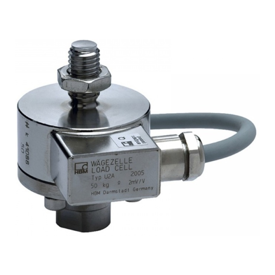
    Berücksichtigen Sie insbesondere die in den technischen Daten genannten Grenzlasten. Bestimmungsgemäßer Gebrauch Die Wägezelle U2A... ist für wägetechnische Anwendungen konzipiert. Jeder darüber hinausgehende Gebrauch gilt als nicht bestimmungsgemäß. Zur Gewährleistung eines sicheren Betriebes darf die Wägezelle nur nach den Angaben in der Montageanleitung verwendet werden. Bei der Verwendung sind zusätzlich die für den jeweiligen Anwendungsfall erforderlichen...
  • Seite 21 Weist darauf hin, dass wichtige Informationen über das Produkt oder über die Handhabung des Produktes gegeben werden. Symbol: Bedeutung: CE-Kennzeichnung Mit der CE-Kennzeichnung garantiert der Hersteller, dass sein Produkt den Anforderungen der relevanten EG-Richtlinien entspricht (die Konformitätserklärung finden Sie unter http://www.hbm.com/HBMdoc). A1261-2.2 en/de/fr...
  • Seite 22 Umgebungsbedingungen Beachten Sie in Ihrem Anwendungsfeld, dass alle Stoffe die (Chlor-) Ionen freisetzen, auch nichtrostende Stähle und deren Schweißnähte angreifen. In diesem Fall sind von der Betreiberseite entsprechende Schutzmaßnahmen vorzusehen. Verbot von eigenmächtigen Umbauten und Veränderungen Die Wägezelle darf ohne unsere ausdrückliche Zustimmung weder konstruktiv noch sicherheitstechnisch verändert werden.
  • Seite 23: Bedingungen Am Einbauort

    Nullpunktveränderung [%/10 mbar] 0,065 0,032 0,016 0,006 0,003 0,006 0,003 0,002 0,001 1.2 Spezielle Hinweise Die Aufnehmer U2A sind vollständig aus nichtrostenden Materialien gefertigt. Die Beständigkeit gegen aggressive Umgebungseinflüsse ist im Einzelfall vom Anwender zu prüfen. Montagehinweise • Den Aufnehmer schonend handhaben.
  • Seite 24: Lasteinleitung

    Lasteinleitung Die Wägezellen der Typenreihe U2A können axiale Lasten sowohl in Zug− als auch in Druckrichtung messen. Zur Einleitung von Zuglasten (Vorzugsrichtung) sind ein Gewindebolzen am Gehäusekopf und ein Innengewinde am Adapter vorgesehen. Für einen seitenkraft− und momentfreien Anschluss an die Waagenkonstruktion empfiehlt HBM die Verwendung von Gelenkösen.
  • Seite 25: Anschließen

    Störspannungen in den Messkreis. Beachten Sie deshalb folgende Hinweise: • Verwenden Sie nur abgeschirmte und kapazitätsarme Messkabel (HBM-Kabel erfüllen diese Bedingungen). • Messkabel nicht parallel zu Starkstrom- oder Steuerleitungen verlegen. Falls dies nicht möglich ist (z.B. in Kabelschächten), schütze man das Messkabel z.B.
  • Seite 26: Parallelschaltung Mehrerer Aufnehmer

    Abweichungen von Kennwert und Temperaturkoeffizient des Kennwertes. 4.5 Kabelverlängerung Verlängerungskabel müssen abgeschirmt und kapazitätsarm sein. Wir empfehlen Ihnen die Verwendung von HBM-Kabeln, die diese Voraussetzungen erfüllen. Bei Kabelverlängerungen ist auf eine einwandfreie Verbindung mit geringsten Übergangswiderständen und gute Isolation zu achten.
  • Seite 27: Technische Daten

    Technische Daten Genauigkeitsklasse Teilezahl (n − − 1000 Nennlast (E 100, 200, − 10, 20 1, 2, 5 Mindestteilungswert (v % v. − − 0,0286 Nennkennwert (C mV/V Kennwerttoleranz <"0,20 <"0,20 <"0,20 bei Zug bei Druck <"1,50 <"0,50 <"0,50 Temperaturkoeffizient des Kennwertes (TK <"0,05 im Nenntemperaturbereich...
  • Seite 28: Mechanische Werte

    II 3 G EEx nA II T6 (Zone 2) II 3 D IP67 T80 °C (Zone 22 für nichtleitenden Staub) *) mit EG−Baumusterprüfbescheinigung Zubehör, zusätzlich zu beziehen: − Gelenköse U2A, oben, U2A/.../ZGOW − Gelenköse U2A, unten, U2A/.../ZGUW − Erdungskabel EEK...
  • Seite 29: Abmessungen (In Mm)

    Abmessungen (in mm) 6.1 Aufnehmer (Nennlasten 50 kg ... 20 t) Draufsicht Nennlast ØA −0,2 in t 0,05 ... 1 10,6 M20x1,5 13,2 M24x2 M39x2 24,2 M48x2 bei U2A/1t: 7,4 mm A1261-2.2 en/de/fr...
  • Seite 30: Einbauhilfen

    Material: Vergütungsstahl, verzinkt; Wälzlagerstahl und PTFE/Bronzegewebefolie ∅B ∅K Nennlast Gelenköse Gewicht SW W in t ZGOW [kg] 0,05...1 U2A/1T/ ZGOW U2A/2T / ZGOW M20x1,5 U2A/5T/ ZGOW M24x2 U2A/10T / ZGOW +0,002 212.5 28 M39x2 -0,014 +0,003 U2A/20T / ZGOW M48x2 -0,018 A1261-2.2 en/de/fr...
  • Seite 31 Material: Vergütungsstahl, verzinkt; Wälzlagerstahl und PTFE/Bronzegewebefolie ∅B Nennlast Gelenköse Gewicht SW W in t ZGUW in kg 0,05...1 U2A/ 1T / ZGUW U2A/ 2T / ZGUW 18 M20x1,5 U2A/5T / ZGUW M24x2 U2A/10T / ZGUW 65,5 +0,002 115 148,5 M39x2...
  • Seite 32 Wägezelle U2A mit montierten Gelenkösen ZGOW, ZGUW Nennlast in 0,05...0,5 Nennlast in Anzugsmoment Mindestein- [NVm] schraubtiefe 0,05...0,5 19,2 19,2 31,2 2500 36,6 38,4 4500 Diesen Wert nicht überschreiten und Wägezelle beim Anziehen schonend handhaben, um eine Beschädigung der dünnen Messmembran zu vermeiden.
  • Seite 33 U2A, mit ZGOW, ohne Adapter um 45° bzw. 22,5° Basisplatte, versetzt gezeichnet kundenseitig *Empfohlenes Maß, unter Beachtung der Mindesteinschraubtiefe ∅G ∅S Nennlast in t [NVm] 0,05...0,5 4xM5 84...86,4 4xM5 86,4 4xM10 20,5 131,6 4xM12 158,2 8xM12 8xM16 270,2 )Empfohlene Werte bei trockenem Gewinde und Benutzung eines Drehmomentschlüssels...
  • Seite 34 A1261-2.2 en/de/fr...
  • Seite 35 Sommaire Page Consignes de sécurité ......... . 1 Conditions concernant le lieu d’installation .
  • Seite 36: Consignes De Sécurité

    être observées. Respecter tout particulièrement les charges limites indiquées dans les caractéristiques techniques. Utilisation conforme Le peson U2A... est conçu pour des applications de pesage. Toute autre utilisation est considérée comme non conforme. Pour garantir un fonctionnement en toute sécurité, le peson doit être utilisé...
  • Seite 37 Signale que des informations importantes sont fournies concernant le produit ou sa manipulation. Symbole : Signification : Marquage CE Par le label CE, le fabricant garantit que son produit satisfait aux conditions des principales directives CE (pour voir la déclaration de conformité visitez http://www.hbm.com/HBMdoc). A1261-2.2 en/de/fr...
  • Seite 38 Conditions ambiantes Considérez dans votre domaine d’applications que toutes les substances libérant des ions (chlore), peuvent agir également sur les aciers inoxidables et leurs sondeus. Donc, l’exploitant doit prévoir des mesures de protection correspondantes. Transformations et modifications interdites sans autorisation Il est interdit de modifier le peson sur le plan conceptuel ou de la sécurité...
  • Seite 39: Conditions Concernant Le Lieu D'installation

    [%/10 mbar] 0,065 0,032 0,016 0,006 0,003 0,006 0,003 0,002 0,001 1.2 Remarques particulières Les capteurs U2A sont entièrement constitués de matériaux inoxydables. La résistance aux influences agressives de l’environnement doit être contrôlée au cas par cas par l’utilisateur.
  • Seite 40: Application De Charge

    Application de charge Les pesons de la série U2A peuvent mesurer des charges axiales aussi bien dans la direction de traction que dans la direction de pression. Pour appliquer des charges en traction (direction privilégiée), un boulon fileté est prévu à la tête du boîtier et l’adaptateur comporte un taraudage.
  • Seite 41: Raccordement

    C’est la raison pour laquelle : • Vous devez utiliser uniquement des câbles de mesure blindés de faible capacité (les câbles HBM satisfont à ces conditions) • Vous ne devez pas poser les câbles de mesure en parallèle avec des câbles de commande et d’énergie.
  • Seite 42: Branchement En Parallèle De Plusieurs Capteurs

    4.5 Rallonge de câbles Les câbles prolongateurs (rallonges) doivent être blindés et de faible capacité. Nous recommandons l’utilisation des câbles HBM qui satisfont à ces conditions requises. Pour les prolongations de câble, il faut veiller à une parfaite connexion avec des résistances de transition minimes et à une bonne isolation.
  • Seite 43: Specifications

    Specifications Type Classe de précision Nombre d’échelons (n − − 1000 Charge nominale (E 100, 200, − 10, 20 1, 2, 5 Valeur min. d’un échelon (v % de − − 0,0286 Valeur caractéristique nominale (C mV/V Tolérance de la valeur caractéristique <"0,20 <"0,20 <"0,20...
  • Seite 44: Caractéristiques Mécaniques

    II 3 D IP67 T80 °C (Zone 22 pour poussière non conductrice) avec certificat d’examen CE de type Accessoires (non compris dans la livraison) : − Anneaux à rotule U2A, pour le haut, U2A/.../ZGOW − Anneaux à rotule U2A, pour le bas, U2A/.../ZGUW...
  • Seite 45: Dimensions (En Mm)

    Dimensions (en mm) 6.1 Capteur (Charges nominales 50 kg...50 t) Sur plats vue de dessus Charge ØA −0,2 nominale plats en t 0,05 ... 1 10,6 M20x1,5 13,2 M24x2 M39x2 24,2 M48x2 avec U2A/1t: 7,4 mm A1261-2.2 en/de/fr...
  • Seite 46: Pièces Pour Le Montage

    Matériau: acier trempé, galvanisé; acier laminé et PTFE/feuillard de bronze ∅B ∅K Charge Anneaux à Poids s.p. W rotule ZGOW [kg] nominal e en t 0,05...1 U2A/1T/ ZGOW U2A/2T / ZGOW M20x1,5 U2A/5T/ ZGOW M24x2 U2A/10T / ZGOW +0,002 212.5 28 M39x2 -0,014 U2A/20T / ZGOW +0,003 M48x2 -0,018...
  • Seite 47 Matériau: acier trempé, galvanisé; acier laminé et PTFE/feuillard de bronze ∅B Charge Anneaux à Poids s.p. rotule ZGOW in kg nominal e en t 0,05...1 U2A/ 1T / ZGUW U2A/ 2T / ZGUW 18 M20x1,5 U2A/5T / ZGUW M24x2 U2A/10T / ZGUW 65,5 50 +0,002 115 148,5 M39x2 -0,014...
  • Seite 48 Peson U2A avec oeillets articulés montés ZGOW, ZGUW Charge nominale en t 0,05...0,5 Charge Profondeur Couple de filetée minimale serrage M nominale [NVm] en t 0,05...0,5 19,2 19,2 31,2 2500 36,6 38,4 4500 Ne pas dépasser cette valeur et manipuler le peson doucement lors de le serrer pour éviter tout...
  • Seite 49 U2A, avec ZGOW, sans adaptateur dessin décalé de 45° plaque de base, ou de 22,5° incombe au client *cote recommandée en veillant à la profondeur filetée minimum ∅G ∅S Charge [NVm] nominale en t 0,05...0,5 4xM5 84...86,4 4xM5 86,4 4xM10...
  • Seite 50 A1261-2.2 en/de/fr...
  • Seite 52 Hottinger Baldwin Messtechnik GmbH 7-2001.0075 Postfach 10 01 51, D-64201 Darmstadt Im Tiefen See 45, D-64293 Darmstadt Tel.: +49 6151 803-0 Fax: +49 6151 8039100 Email: support@hbm.com Internet: www.hbm.com A1261-2.2 en/de/fr...

Inhaltsverzeichnis