
Verwandte Anleitungen für Sartorius BioPAT Xgas

Inhaltszusammenfassung für Sartorius BioPAT Xgas
- Seite 1 Operating Instructions | Betriebsanleitung BioPAT Xgas ® 85032-544-12 85032-544-12...
- Seite 2 English page Deutsch Seite The enclosed CD contains the operating instructions as a PDF file in various international languages. If the CD is missing, you can obtain a copy form us by specifying the order number: Order number: 85037-548-53 System Requirements: −...
-
Seite 3: Inhaltsverzeichnis
Contents Contents 1 Introduction . . . . . . . . . . . . . . . . . . . . . . . . . . . . . . . . . . . . . . . . . . . . . . . . . . . . . . . . . . . . . 5 Function . - Seite 4 Contents 5 Operating Information . . . . . . . . . . . . . . . . . . . . . . . . . . . . . . . . . . . . . . . . . . . . . . . . . .25 5.1 Safety Instructions .
-
Seite 5: Introduction
These instructions are part of the product. Keep them in a safe and easily accessible place near the device’s site of installation. If the instructions should be lost or misplaced, please contact Sartorius Stedim Biotech for a replacement or download the latest version from our website: www.sartorius.com... - Seite 6 Introduction Symbols Used As a means of instruction and direct warning against hazards, all text statements to be particu- larly noted in these operating instructions will be marked as follows: This symbol denotes a possible danger with risk that moderate or minor injury may result if it is not avoided.
-
Seite 7: Safety Instructions
Safety Instructions Safety Instructions General Information Sartorius Stedim Biotech supplies the BioPAT Xgas after careful testing in ® ready-for-operation condition. This manual contains instructions for the safe operation of the BioPAT Xgas. ® You may only operate the device under conditions that comply with the specifications stated in this manual and the information on the manufacturer’s... -
Seite 8: Limitations Of Use And Misuse
Safety Instructions Limitations of Use and Misuse Danger of malfunctions and damage to the sensor under impermissible measuring IMPORTANT conditions! The BioPAT Xgas is not designed according to ® the ATEX Directive. Do not use the sensor − in flammable or explosive atmospheres or with such gases! −... -
Seite 9: Process-Related Hazards
Safety Instructions Process-related Hazards Risk of poisoning for persons when CO released into the room! Risk of inflammation for flammable materials if gases enriched with CAUTION oxygen escape into the room air! Determine the max. concentrations of gas released into the room and evaluate whether they could lead to hazardous situations, e.g. -
Seite 10: Design And Function
Design and Function The BioPAT Xgas combines one oxygen and one carbon dioxide sensor ® featuring automatic compensation of humidity and pressure into one compact analyzer. The gas to be analyzed flows through the integrated flow adapter past the measuring chambers. During this process, the pressure, humidity, oxygen and carbon dioxide concentration are measured. The sensors measure the gases in the concentration ranges and under the conditions for which they were designed; observe the → Technical Data. - Seite 11 Design and Function Electronics Pressure and humidity sensor measurement IR sensor For hoses | pipes AD4 mm up to 1 1/4“ Fig. 1: Schematic illustration of complete installation In order to prevent humidity contained in the exhaust air in the BioPAT Xgas ® from condensing, the sensor housing is heated. Warming up prior to initial startup as well as every time the device is disconnected from the power supply will take about an hour.
-
Seite 12: Pressure Measurement
Design and Function 3.1.1 Pressure Measurement A piezoresistive silicon pressure sensor is used to measure the pressure. 3.1.2 Humidity Measurement A capacitive polymer sensor is used to measure the humidity. 3.1.3 CO₂ Measurement The CO₂ sensor comprises an IR radiation source, a detector and the reflection measuring cell (Fig. 2). The infrared beam is reflected by the gas-filled measuring adapter. -
Seite 13: Installation
Installation Installation Equipment Danger of malfunctions when damaged during transport and when operated under process IMPORTANT conditions that do not comply with the device specifications! When delivered for or with bench-top bioreactor systems, e.g. Biostat B or B-DCU II, the BioPAT ®... -
Seite 14: Unboxing And Assembling
The delivery contains the matching plug adapter. − A replacement BioPAT Xgas power supply kit ® pack can be ordered from Sartorius Stedim Biotech (SB-20-02-0002), see “Fig. 5: Cable set included“. 4.1.1 Unboxing and assembling The flow adapter of the BioPAT Xgas is not ®... - Seite 15 Installation To assemble the BioPAT Xgas proceed in the ® following steps: First, place the filters and gaskets on the flow adapter. All required filters and gaskets are in the filter set for the BioPAT Xgas ® (SB-20-02-0001, Spare part kit for BioPAT ® Xgas). For each recess there are two different filters.
- Seite 16 Installation Insert the thicker filters into the recesses (fig. 4g). If the filters don´t fit in the recesses, it might be necessary to push them gently into place (fig. 4h). Fig. 4g: Insert second filter Fig. 4h: Fit in filter Now place the 4 TORX screws M4x16 (fig. 4b: E) in the bores of the BioPAT Xgas without ®...
-
Seite 17: Setup
Installation Setup Danger of damage to the control and supply unit of the bioreactor! IMPORTANT The BioPAT Xgas module weighs approx. 3 kg. ® Do not place the module on the control and supply unit of the bioreactor and do not fasten it to its side panels. -
Seite 18: Connection
Installation Connection Making connections while the BioPAT Xgas is ® still connected to power or with the wrong kind IMPORTANT of voltage can cause damage! Use only cables from the equipment supplied with the BioPAT Xgas and | or the bioreactor ®... - Seite 19 Installation Connecting the Cables to the Biostat B and ® B-DCU II Use only the cables that are especially designed for this purpose. Observe the specifications below and the “Technical Documentation on the Bioreactor“. Wait until the BioPAT Xgas has reached ®...
- Seite 20 Installation Connecting to Biostat B (Serial No. ≤ 1000) ® Connect the analog signal outputs of the BioPAT Xgas to the analog inputs on the ® Control Tower of the Biostat B as follows: ® Take the analog Y signal cable. Connect the plug of the Y cable labeled “Xgas”...
- Seite 21 Installation Connecting to Biostat B-DCU II ® Connect the analog signal outputs of the BioPAT Xgas to the analog inputs on the ® Control Tower of the Biostat B-DCU II as ® follows: Take the analog Y signal cable. Connect the plug of the Y cable labeled “Xgas”...
- Seite 22 Installation Connecting to Biostat B (Serial No. > 1000) ® Connect the analog signal outputs of the BioPAT Xgas to the analog inputs on the ® control tower of the Biostat B as follows: ® Take the analog signal cable. Connect the cable plug labeled “Xgas”...
- Seite 23 Installation Connecting to Biostat C Plus ® Connect the analog signal outputs of the BioPAT Xgas to the control tower of the ® Biostat C Plus as follows: ® Take the analog serial connection cable. Connect the cable plug labeled “Xgas” to the right-hand socket of the BioPAT Xgas.
-
Seite 24: Arrangement On The Bioreactor And Assembly
Installation Arrangement on the Bioreactor and Assembly Fitting the BioPAT Xgas to a Biostat C Plus: ® ® Pos . Description BioPAT Xgas Sensor & flowpath module ® Support C1/C2 Valves for switching the exhaust feed Pneumatic pressure control valve Pipe to BioPAT Xgas sensor ®... -
Seite 25: Operating Information
Operating Information Operating Information Safety Instructions Hazards for users from the composition of the exhaust air! − CO : Danger of suffocation from release into CAUTION the room air; − O : Combustion of flammable materials at high O concentrations or potential produc- tion of oxy-hydrogen gas with H When channeling into room air, ensure that your work area is well ventilated. -
Seite 26: In-Process Exhaust Air Analysis
Operating Information In-process Exhaust Air Analysis Danger of burns! After connecting the power supply, the housing of the BioPAT Xgas heats ® up due to warming! CAUTION Do not touch it any longer or only when wearing gloves. Compare the process conditions with the bio- reactor specifications in the “Technical Data“. - Seite 27 Operating Information Perform 1-point calibration during initial start- up and always when the analyzer indicates you do so. Disconnect the connection or lines from the bioreactor (exhaust air filter) and channel fresh air (0.04% CO , 20.97% O volume, residual N ) at a flow rate of min.
-
Seite 28: In-Process Measurement
Operating Information 5.2.2 In-process Measurement Temperatures in the exhaust air >40°C or oxygen-free exhaust air can damage the sensors IMPORTANT in the BioPAT Xgas! ® The pure nitrogen used during zero-point cali- bration of the DO sensor in the culture vessel must not escape into the BioPAT Xgas. - Seite 29 Operating Information Biostat C Plus bioreactors ® If the zero point of the DO sensor with oxygen is calibrated, switch the exhaust line to the bypass via the solenoid valves. Calibrate the zero point of the built-in DO sensor with nitrogen. Ensure that the process temperature is below 40°C.
-
Seite 30: Sensor Status Display Via Leds
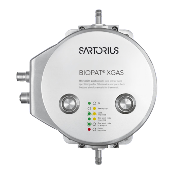
Operating Information 5.2.3 Sensor Status Display via LEDs LED status Description Possible Causes green Sensor is ready for operation yellow Warm-up phase, can take The sensors must reach operat- up to 60 minutes ing temperature, otherwise the measurements are incorrect green | Prompt to perform a 1-point Always at the initial startup,... -
Seite 31: Troubleshooting
Operating Information Troubleshooting 5.3.1 Faults or Malfunctions from Moisture in the Exhaust Air Humidity, e .g . condensation in the exhaust line, can damage the sensors in the BioPAT Xgas or ® IMPORTANT disrupt the exhaust measurement! In the event of moist exhaust air that is warmer than the ambient air, condensation can form in the exhaust line and be forced into the module. -
Seite 32: Leaktightness Test
Operating Information 5.3.2 Leaktightness Test Ambient air entering the exhaust air disrupts the measurement! IMPORTANT Check whether the tubing, lines, connections and the BioPAT Xgas are leaktight. ® Block the gas outlet of the BioPAT Xgas or ® clamp off the lines to the exhaust air fittings in the laboratory. -
Seite 33: Maintenance And Service
| 0.04% by volume CO ) as per specification (see Data Sheet). Next, press the two keys at the same time for 5 seconds (Fig. 8). For the recommended annual recalibration, return the sensor to Sartorius Stedim Biotech. Operating Instructions BioPAT Xgas ®... -
Seite 34: Filter Replacement
Maintenance and Service 6.1.2 Filter Replacement The flow adapter contains a coarse filter, which you have to maintain and replenish whenever there are impurities or obstructions of the gas flow. Spare parts are obtained on request. For filter replacements: Disconnect all connected lines from the BioPAT Xgas or disassemble the module ®... - Seite 35 1-point calibration, in the event of strong signal alteration without major changes to the measuring conditions. Sartorius Stedim Biotech shall not be liable for repairs made by the customer or any resulting damage, especially in the event of −...
-
Seite 36: Appendix
Appendix Appendix Calibration Table Only have the complete calibration conducted by Sartorius Stedim Biotech Service. Conduct the monthly 1-point calibration as described in Section → “6.1.1 Calibration”, page 33. Also calibrate this way every time after separating sensor head and measuring adapter. Log the calibrations performed, e.g. in the table below. -
Seite 37: Technical Data
Technical Data Technical Data Sensor Unit Concentration range 1 – 50% by volume, others available upon request Measuring principle Zirconium dioxide Accuracy < 0.2% FS2 ± 3% Rdg2 on value Drift < ± 2% value | year Lifetime of sensor Approx. - Seite 38 Technical Data General Information Temperature range 15 – 40°C Pressure range 0.8 – 1.3 bar 11.6 – 18.85 psi absolute pressure Humidity range 0 – 100% relative operating humidity, integrated humidity compensation Housing Stainless steel, IP65 Dimensions | Weight W × L × H = 170 × 150 × 120 mm | weight = 4 kg Mechanical connection ¼“...
- Seite 39 Technical Data Electronic Connections Power supply 12-pin M12 male connector Signal output 12-pin M12 female connector Electronic output Active output, maximum 505 Ohm at 24V power supply RS-232, RS-485, USB, Ethernet (with BACCom), Modbus Storage 0 – +60°C; < 75% RF non-condensing Maintenance 1-point calibration with fresh air (0.04 vol.% CO 20.97 vol.% O...
-
Seite 40: Disposal
The packaging is made of environmentally friendly materials that can be used as secondary raw materials. 9.2.2 Disposal Dispose of the device taking into account the disposal information on our website (www.sartorius.com). Dispose of the packaging in accordance with local government regulations. Operating Instructions BioPAT Xgas... -
Seite 41: 10 Conformity Documents
Conformity Documents 10 Conformity Documents The attached documents confirm compliance of the device with the directives or standards cited. Operating Instructions BioPAT Xgas ®... - Seite 42 Inhalt Inhalt 1 Einleitung . . . . . . . . . . . . . . . . . . . . . . . . . . . . . . . . . . . . . . . . . . . . . . . . . . . . . . . . . . . . . . .44 Funktion .
- Seite 43 Inhalt 5 Betriebshinweise . . . . . . . . . . . . . . . . . . . . . . . . . . . . . . . . . . . . . . . . . . . . . . . . . . . . . . . .64 5.1 Sicherheitshinweise .
-
Seite 44: Einleitung
Diese Betriebsanleitung ist Teil des Gerätes. Bewahren Sie sie gut erreichbar und sicher am Einsatzort des Geräts auf. Bei Verlust der Anleitung fordern Sie Ersatz an bei Sartorius Stedim Biotech oder laden Sie die aktuelle Version von unserer Internetseite herunter: www.sartorius.com... - Seite 45 Einleitung Darstellungsmittel Als Hinweis und zur direkten Warnung vor Gefahren sind besonders zu beachtende Textaussagen in dieser Betriebsanleitung wie folgt gekennzeichnet: Dieser Hinweis kennzeichnet mögliche Gefähr- dungen, die zu mittelschweren oder leichte Körper verletzungen führen können, wenn Sie sie VORSICHT nicht vermeiden.
-
Seite 46: Sicherheitshinweise
Sicherheitshinweise Sicherheitshinweise Allgemeines Die Sartorius Stedim Biotech liefert der BioPAT Xgas nach sorgfältiger ® Prüfung in betriebsbereitem Zustand. Diese Anleitung enthält Hinweise für den sicheren Betrieb des BioPAT Xgas. ® Verwenden Sie das Gerät nur gemäß den Angaben in dieser Anleitung und unter Bedingungen, die den Spezifikationen auf dem Typenschild entsprechen. -
Seite 47: Verwendungsbeschränkungen Und Fehlgebrauch
Sicherheitshinweise Verwendungsbeschrän- kungen und Fehlgebrauch Gefahr von Fehlfunktionen und Beschädigung des Sensors bei unzulässigen Messbedingungen! ACHTUNG Der BioPAT Xgas ist nicht ausgelegt gemäß ® ATEX-Richtlinie. Verwenden Sie den Sensor nicht − in brennbaren oder explosiven Atmosphä- ren oder mit solchen Gasen! −... -
Seite 48: Prozessabhängige Gefahren
Sicherheitshinweise Prozessabhängige Gefahren Vergiftungsgefahr für Personen bei Anreiche- rung von CO im Raum . Entzündungsgefahr für entflammbare Stoffe, wenn mit O angereicher- VORSICHT te Gase in die Raumluft gelangen! Ermitteln Sie die max. Gaskonzentrationen bei Anreicherung im Raum und bewerten, ob dies zu gefährlichen Situationen führen kann, z. -
Seite 49: Aufbau Und Funktion
Aufbau und Funktion Aufbau und Funktion Aufbau und Funktion Der BioPAT Xgas kombiniert je einen CO - und O -Sensor mit einer automa- ® tischen Feuchte- und Druckkompensation in einem kompakten Analyse- gerät. Das zu untersuchende Gas strömt über den integrierten Flussadapter an drei Messkammern vorbei, die Druck, Feuchte sowie CO - und O -Gehalt... - Seite 50 Aufbau und Funktion Elektronik Druck- und -Sensor Feuchtemessung -IR-Sensor Für Schläuche | Rohre AD4 mm bis 1 ¼“ Abb. 1: Schematische Darstellung des Gesamtaufbaus Damit in der Abluft enthaltene Feuchtigkeit im BioPAT Xgas nicht auskon- ® densieren kann, ist das Sensorgehäuse beheizt. Das Aufwärmen dauert ca. 1 Stunde, sowohl bei der ersten Inbetriebnahme als auch nach jeder Trennung der Spannungsversorgung Während der Aufwärmzeit gibt der Sensor keine gültigen Messwerte aus.
-
Seite 51: Druckmessung
Aufbau und Funktion 3.1.1 Druckmessung Ein piezoresistiver Siliziumdrucksensor misst den Druck. 3.1.2 Feuchtigkeitsmessung Ein kapazitiver Polymerfühler misst die Feuchtigkeit. 3.1.3 -Messung Der CO -Sensor besteht aus der IR-Strahlungs- quelle, dem Detektor und der Reflektionsmess- zelle (Abb. 2). Der gasgefüllte Messadapter reflektiert den Infrarot-Lichtstrahl. -
Seite 52: Installation
Installation Installation Ausrüstungen Gefahr von Fehlfunktionen bei Beschädigung durch den Transport und bei Prozessbedingungen, ACHTUNG die nicht den Gerätespezifikationen entsprechen! Bei Lieferung für oder mit Tischgeräten der Bio- reaktoren, z. B. Biostat B oder B-DCU II, sind der ® BioPAT Xgas und das Zubehör transport sicher ®... -
Seite 53: Auspacken Und Zusammenbauen
Xgas an die Kontrolleinheit. − Bei Lieferung mit dem externen Netzteil muss der Stecker zum Netzanschluss im Labor passen. Die Lieferung enthält passende Steck adapter. − Bei Sartorius Stedim Biotech kann ein Ersatz-Netzteilkit für BioPAT Xgas bestellt ® werden (SB-20-02-0002), siehe „Abb. 5: Kabelsatz im Lieferumfang“. - Seite 54 Installation Um den BioPAT Xgas zusammenzubauen, ® gehen Sie folgendermaßen vor: Legen Sie zuerst die Filter und Dichtungen auf den Durchflussadapter. Alle erforder- lichen Filter und Dichtungen sind im Filterset für den BioPAT Xgas (SB-20-02-0001, ® Ersatzteilkit für BioPAT Xgas) enthalten. ®...
- Seite 55 Installation Legen Sie die dickeren Filter in die Vertiefun- gen ein (Abb. 4g). Wenn die Filter nicht in die Vertiefungen passen, kann es erforderlich sein, sie vorsichtig hineinzudrücken (Abb. 4h). Abb. 4g: Einlegen des zweiten Filters Abb. 4h: Hineindrücken des Filters Legen Sie nun die 4 TORX Schrauben M4x16 (Abb.
-
Seite 56: Aufstellung
Installation Aufstellung Gefahr von Schäden an Kontroll- bzw . Versorgungseinheit des Bioreaktors! ACHTUNG Das BioPAT Xgas-Modul wiegt ca. 3 kg. ® Stellen Sie das Modul nicht auf die Kontroll- oder Versorgungseinheit des Bioreaktors und befestigen Sie es nicht an deren Seiten- blechen. -
Seite 57: Anschluss
Installation Anschluss Das Anschließen unter Spannung oder eine falsche Spannungsversorgung können den ACHTUNG BioPAT Xgas beschädigen! ® Verwenden Sie nur die Kabel aus dem Liefer- umfang des BioPAT Xgas bzw. der Ausrüs- ® tung für den Bioreaktor. Das Modul besitzt keinen Ein- | Aus-Schalter. - Seite 58 Installation Anschließen der Kabel beim Biostat B und ® B-DCU II Verwenden Sie nur die speziellen, hierfür ausgelegten Kabel. Beachten Sie die Angaben unten und die „Technische Doku- mentation zum Bioreaktor“. Warten Sie, bis der BioPAT Xgas Raumtem- ® Abb. 5: Kabelsatz im peratur erreicht hat.
- Seite 59 Installation Anschluss an Biostat B (Serien-Nr. ≤ 1000) ® Schließen Sie die analogen Signalausgänge des BioPAT Xgas wie folgt an die analogen ® Eingänge am Control Tower des Biostat B an: ® Nehmen Sie das analoge Y-Signalkabel. Verbinden Sie den mit „Xgas“ beschrifte- ten Stecker des Y-Kabels mit der rechten Buchse des BioPAT Xgas.
- Seite 60 Installation Anschluss an Biostat B-DCU II ® Schließen Sie die analogen Signalausgänge des BioPAT Xgas wie folgt an die analogen ® Eingänge am Control Tower des Biostat ® B-DCU II an: Nehmen Sie das analoge Y-Signalkabel. Verbinden Sie den mit „Xgas“ beschrifte- ten Stecker des Y-Kabels mit der rechten Buchse des BioPAT Xgas.
- Seite 61 Installation Anschluss an Biostat B (Serien-Nr . größer ® 1000) Schließen Sie die analogen Signalausgänge des BioPAT Xgas wie folgt an die analogen ® Eingänge am Control Tower des Biostat B an: ® Nehmen Sie das analoge Signalkabel. Verbinden Sie den mit „Xgas“ beschrifte- ten Stecker des Kabels mit der rechten Buchse des BioPAT Xgas.
- Seite 62 Installation Anschluss an Biostat C Plus ® Schließen Sie die analogen Signalausgänge des BioPAT Xgas wie folgt am Control Tower ® des Biostat C Plus an: ® Nehmen Sie das analoge Signalkabel. Verbinden Sie den mit „Xgas” beschrifte- ten Stecker des Kabels mit der rechten Buchse des BioPAT Xgas.
-
Seite 63: Übersichtsdarstellung Für Aufstellung Und Montage
Installation Übersichtsdarstellung für Aufstellung und Montage Aufbau BioPAT Xgas am Biostat C Plus: ® ® Pos . Beschreibung BioPAT Xgas Sensor mit Flussadapter ® Halteblech C1/C2 Ventile zum Umschalten der Abgasleitungen Pneumatisches Druckregelventil Rohrleitung zum BioPAT Xgas Sensor ® Rohrleitung zwischen Abluftventil und Druckregelventil G1/G2 Abluftausgänge in die Umgebung oder zur Verbindung mit dem Laborabzug (falls erforderlich) -
Seite 64: Betriebshinweise
Betriebshinweise Betriebshinweise Sicherheitshinweise Gefahren für Anwender durch die Beschaffen- heit der Abluft! − CO : Erstickungsgefahr bei Anreicherung in VORSICHT der Raumluft; − O : Entzündung brennbarer Stoffe bei hoher Konzentration oder mögliche Knallgas- bildung mit H Beim Ableiten in die Raumluft sorgen Sie für gute Belüftung am Arbeitsplatz. -
Seite 65: Abluftanalyse Im Prozess
Betriebshinweise Abluftanalyse im Prozess Verbrennungsgefahr! Durch das Aufwärmen nach Anschließen der Spannungsversorgung erhitzt sich das Gehäuse des BioPAT Xgas! ® VORSICHT Nach Anschließen der Spannungsversorgung nicht mehr oder nur mit Schutzhandschuhen berühren. Vergleichen Sie die Prozessbedingungen mit den Gerätespezifikationen in den „Techni- schen Daten“. - Seite 66 Betriebshinweise Machen Sie beim ersten Start und immer, wenn das Analysegerät dies anzeigt, eine 1-Punkt-Kalibrierung. Trennen Sie die Verbindung oder Leitung vom Bioreaktor (Abluftfilter) und führen Frischluft (0,04% , 20,97 Vol.% O , Rest N ) bei einem Durchfluss von min. 200 ml/min. Beachten Sie die Spezifikationen im „Datenblatt“. Abb.
-
Seite 67: Messbetrieb Im Prozess
Betriebshinweise 5.2.2 Messbetrieb im Prozess Temperaturen in der Abluft von über 40°C oder sauerstofffreie Abluft beschädigen die Sensoren ACHTUNG im BioPAT Xgas! ® Feuchtigkeit und Kondensat in der Abluft kann die Sensoren beschädigen. Stellen Sie sicher, dass die Abluftkühlung während der Messung immer aktiv ist. - Seite 68 Betriebshinweise Bioreaktoren Biostat C Plus ® Falls der Nullpunkt des pO -Sensors mit Stick- stoff kalibriert wird, schalten Sie die Abluft- strecke über die Magnetventile auf Bypass. Kalibrieren Sie den Nullpunkt des im Bioreak- tor eingebauten pO -Sensors mit Stickstoff. Stellen Sie sicher, dass die Prozesstemperatur unter 40°C liegt.
-
Seite 69: Zustandsanzeige Des Sensors Über Leds
Betriebshinweise 5.2.3 Zustandsanzeige des Sensors über LEDs LED-Zustand Beschreibung Mögliche Ursache grün Sensor ist betriebsbereit gelb Aufheizphase, sie kann bis die Sensoren müssen Betriebs- zu 60 Minuten dauern temperatur erreichen, ansons- ten sind die Messwerte falsch grün | gelb Aufforderung, eine immer bei der ersten Inbetrieb- 1-Punkt-Kalibrierung nahme, oder das Sensorsignal... -
Seite 70: Fehlerbehebung
Betriebshinweise Fehlerbehebung 5.3.1 Störungen durch Feuchtigkeit in der Abluft Feuchtigkeit, z . B . Kondensat in der Abluft- leitung, kann die Sensoren im BioPAT Xgas ® ACHTUNG beschädigen oder die Abgasmessung stören! Bei feuchter Abluft, die wärmer ist als die Umge- bungsluft, kann sich in der Abluftleitung Konden- sat bilden und in das Modul gedrückt werden. -
Seite 71: Dichtheitsprüfung
Betriebshinweise Wenn häufig größere Kondensatmengen auftreten und Sie den BioPAT Xgas immer ® wieder trocknen müssen, können Sie die Abluft über eine Kondensatfalle leiten [→ Informationen auf Anfrage]. 5.3.2 Dichtheitsprüfung In die Abluft eingetragene Umgebungsluft stört die Messung! ACHTUNG Prüfen Sie, ob die Schläuche, Leitungen, Anschlüsse und der BioPAT Xgas dicht sind. -
Seite 72: Wartung Und Service
| 0,04 Vol. % CO ); je nach Spezifikation (siehe Datenblatt). Anschließend die beiden Taster gleichzeitig für 5 Sekunden betätigen (Abb. 8). Zur empfohlenen 1× jährlichen Rekalibrierung senden Sie den Sensor an Sartorius Stedim Biotech zurück. Betriebsanleitung BioPAT Xgas ®... -
Seite 73: Filterwechsel
Wartung und Service 6.1.2 Filterwechsel Der Durchflussadapter enthält Grobfilter, die Sie bei Verunreinigung und Behinderung des Gasdurchlasses warten und erneuern müssen. Ersatzteile erhalten Sie auf Anfrage. Zum Austauschen der Filter Lösen Sie alle angeschlossenen Leitungen vom BioPAT Xgas oder demontieren das ®... - Seite 74 LED zeigt fehlerhaft arbeitende oder defekte Sensoren an. Vorort-Reparaturen sind nicht möglich. Informie- ren Sie den Service der Sartorius Stedim Biotech. Die Sartorius Stedim Biotech empfiehlt, den Sensor einmal jährlich im Werk überprüfen und rekalibrieren zu lassen. Darüber hinaus senden Sie den Sensor zurück bei falscher bzw.
- Seite 75 Wartung und Service Die Sartorius Stedim Biotech haftet nicht für kundenseitige Reparaturen und resultierende Folgeschäden, insbesondere nicht bei − Verwendung von nicht freigegebenen Ersatzteilen. − Nicht genehmigten technischen Änderungen. Inspektionen kann autorisiertes Servicepersonal vor Ort oder jede Service- Vertretung der Sartorius Stedim Biotech ausführen.
-
Seite 76: Anhang
Anhang Anhang Kalibrationstabelle Lassen Sie die vollständige Kalibrierung nur vom Service der Sartorius Stedim Biotech durchführen. Führen Sie die monatliche 1-Punkt-Kalibrierung durch wie in Abschnitt → „6.1.1 Kalibrierung“, Seite 72, beschrieben. Kalibrieren Sie so auch nach jeder Trennung von Sensorkopf und Messadapter. Protokollieren Sie durchgeführte Kalibrierungen, z. B. in der Tabelle unten. -
Seite 77: Technische Daten
Technische Daten Technische Daten Sensoreinheit Konzentrationsbereich 1 – 50 Vol. %, weitere auf Anfrage Messprinzip Zirkoniumdioxid Genauigkeit < 0,2% Messbereichsendwert ± 3% Anzeige Drift < ± 2% Anzeige/Jahr Haltbarkeit des Sensor elements ca. 15.000 Betriebsstunden | ca. 2 Jahre Interne Sensortemperatur 580°C Sensoreinheit Konzentrationsbereich 0 –... -
Seite 78: Allgemein
Technische Daten Allgemein Temperaturbereich 15 – 40°C Druckbereich 0,8 – 1,3 bar 11,6 – 18,85 psi Absolutdruck Feuchtebereich 0 – 100% relative Feuchte in Betrieb, integrierte Feuchtigkeitskompensation Gehäuse Edelstahl, IP65 Abmessungen | Gewicht B × L × H = 170 × 150 × 120 mm | Gewicht = 4 kg Mechanischer Anschluss ¼“... - Seite 79 Technische Daten Elektronische Verbindungen Spannungsversorgung 12pol M12 Stecker Signalausgang 12pol M12 Buchse Elektrischer Ausgang aktiver Ausgang, maximale Bürde 505 Ohm bei 24 V Spannungsversorgung RS232, RS485, USB, Ethernet (mit BACCom), Modbus Lagerung 0 – +60°C; < 75% RF nicht kondensierend Wartung 1-Punkt-Kalibration mit Frischluft (0,04 Vol.% , 20,97 Vol.% O...
-
Seite 80: Entsorgung
Das Gerät und das Zubehör zum Gerät müssen fachgerecht durch Entsorgungseinrichtungen entsorgt werden. Die Verpackung besteht aus umweltfreundlichen Materialien, die als Sekundärrohstoffe dienen können. 9.2.2 Entsorgen Das Gerät entsorgen. Dazu die Entsorgungshinweise auf unserer Internetseite (www.sartorius.com) beachten. Die Verpackung gemäß den landesrechtlichen Bestimmungen entsorgen. Betriebsanleitung BioPAT Xgas ®... -
Seite 81: 10 Dokumente Zur Konformität
Dokumente zur Konformität 10 Dokumente zur Konformität Mit den beigefügten Dokumenten wird die Übereinstimmung des Geräts mit den benannten Richtlinien oder Normen erklärt. Betriebsanleitung BioPAT Xgas ®... - Seite 82 H H e e r r s s t t e e l l l l e e r r Sartorius Stedim Biotech GmbH M M a a n n u u f f a a c c t t u u r r e e r r 37070 Goettingen, Germany erklärt in alleiniger Verantwortung, dass das Betriebsmittel...
- Seite 83 The information and figures contained in these instructions correspond to the version date specified below. Sartorius reserves the right to make changes to the technology, features, specifications and design of the equipment without notice. Masculine or feminine forms are used to facilitate legibility in these instructions and always simultaneously denote all genders.