CEA COMPACT 240M Bedienungsanleitung & Ersatzteilliste
Vorschau ausblenden
Andere Handbücher für COMPACT 240M:
- Bedienungsanleitung & ersatzteilliste (92 Seiten)
Inhaltsverzeichnis
Manuale d'istruzioni
IT
Lista ricambi
Operator's manual
EN
Spare parts list
Manuel d'instructions
FR
Liste pièce de rechange
Bedienungsanleitung
DE
Ersatzteilliste
Manual de instrucciones
ES
Lista repuestos
Gebruikershandleiding
NL
Onderdelenlijst
Manual de instruções
PT
Lista de peças de substituição
Brugerhåndbog
DA
Liste over reservedele
Ågarhandbok
SV
Reservdelslista
Omistajankäsikirja
FI
Varaosaluettelo
Eierens håndbox
N
Reservedelliste
EL
RU
CEA COSTRUZIONI ELETTROMECCANICHE ANNETTONI S.p.A.
Tel. ++39.0341.22322 - Fax ++39.0341.422646
e-mail: cea@ceaweld.com - web: www.ceaweld.com
C.so E. Filiberto, 27 - 23900 Lecco - Italy
Cas. Post. (P.O.BOX) 205
2
LEGGERE
ATTENTAMENTE
90-96
8
READ
CAREFULLY
90-96
14
LIRE
ATTENTIVEMENT
90-96
20
SORGFÄLTIG
LESEN
90-96
26
LEER
ATENTAMENTE
90-96
32
EERST GOED
DOORLEZEN
90-96
38
LER
ATENTEMENTE
90-97
44
LÆS
OMHYGGELIGT
90-97
50
LÄS
NOGAS
90-97
56
LUE
HUOLELLISESTI
90-97
62
LES
NØYE
90-97
68
90-97
74
90-97
Inhaltsverzeichnis

Verwandte Anleitungen für CEA COMPACT 240M


Inhaltszusammenfassung für CEA COMPACT 240M
- Seite 1 90-97 Omistajankäsikirja HUOLELLISESTI Varaosaluettelo 90-97 Eierens håndbox NØYE Reservedelliste 90-97 90-97 90-97 CEA COSTRUZIONI ELETTROMECCANICHE ANNETTONI S.p.A. C.so E. Filiberto, 27 - 23900 Lecco - Italy Tel. ++39.0341.22322 - Fax ++39.0341.422646 Cas. Post. (P.O.BOX) 205 e-mail: cea@ceaweld.com - web: www.ceaweld.com...
-
Seite 2: Inhaltsverzeichnis
Usage limits (IEC 60974-1) culture and for maintenance. How to lift up the system The main features of COMPACT 240M welders are: • Exceptional welding characteristics with all materials as a re- Assembling the welding machine sult of inductance levelling. -
Seite 3: Assembling The Welding Machine
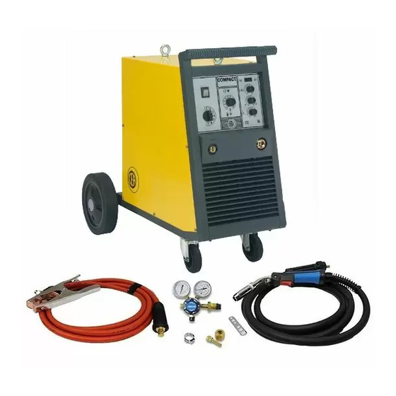
COMPACT Model The standard composition of this welding installation consists 240M Single-phase power supply 50/60 Hz • COMPACT 240M generator. Mains supply: Z • Ground lead integrated with the machine 3 m long. Power input @ I 11,9 The supply also includes the rear wheels for moving the weld-... -
Seite 4: Installation
Table 2 Installation COMPACT Model Select the location of the machine to ensure satisfactory and 240M reliable service. Before installing the welding set the user must Power input @ I 11,9 take into account possible electromagnetic problems of the Delayed fuse (I @ 60%) working area. -
Seite 5: Connection Of Torch And Ground Wire
Pos. 8 Yellow thermostat protection LED. This LED lights up Welding when the overheating protection trips. You are work- ing beyond the work cycle (see “Limits of use”). Wait IMPORTANT: Before welding, check that the data on the power a few minutes before continuing the welding. source plate correspond to the supply voltage and frequency. -
Seite 6: Maintenance
FIG. G Maintenance IMPORTANT: Any eventual maintenance must be carried out by expert, qualified personnel. The guarantee is invalidated if the final user attempts to repair any damage done to the ma- chine by himself. WARNING: Before carrying out any inspection of the inside of the generator, disconnect the system from the supply. -
Seite 7: Troubleshooting Table
Troubleshooting table Problem Cause Remedy The line fuses burn out and • Wrong connection • Check and follow the close the line circuit breaker instructions for connection • Short circuit on fan motor • Repair or replace the motor The line fuses burn out when •... -
Seite 8: Wiring Diagram
IT Schema elettrico DE Schaltplan EN Wiring diagram ES Esquema eléctrico FR Schéma électrique NL Elektrisk skema 2101E773... - Seite 9 •1 •2 •3 •4 •5 •6 •7 •8 •9 •10 •11 •12 •13 •14 •15 •16 •17 •18 •19 •20 •21 •22 •23 •24 •25 •26 •27 •28 •29 •30 •31 •32 •33 •34 •35 TMAX TMIN IT Legenda schema elettrico DE Schaltplan-Legende •1 Bobina contattore di linea •2 Bobina primaria •3 Bobina secondaria •1 Bobine von dem Leistungkontaktgeber •2 Primärspule •3 Sekundärspule...
- Seite 10 PT Esquema eléctrico Elektriske skjema DA Forbindelsesdiagram SV Elektiska schema FI Sähkökaavio 2101E773...
- Seite 11 •1 •2 •3 •4 •5 •6 •7 •8 •9 •10 •11 •12 •13 •14 •15 •16 •17 •18 •19 •20 •21 •22 •23 •24 •25 •26 •27 •28 •29 •30 •31 •32 •33 •34 •35 TMAX TMIN PT Legenda do esquema eléctrico Tegnforklaring av elektrisk skjema •1 Bobina contactor linha •2 Bobina primária •3 Bobina secundária •4 •1 Spole kontaktor for linjen •2 Primærspole •3 Sekundærspole •4...
- Seite 12 IT Legenda colori Cinza Amarelo Castanho Arancio Preto Azzurro Cor-de-rosa Bianco Vermelho Verde Giallo Verde Roxo Grigio Giallo Marrone DA Nøgle til farver Nero Rosa Orange Rosso Lyseblå Verde Hvid Viola Blå Gul Grøn EN Colour key Grå Brun Orange Sortt Sky Blue Rosa...
- Seite 13 IT Regolazione scheda elettronica SV Reglering av kretskortet Trimmer RT1: Regolazione velocità minima filo Trimmer RT1: Reglering av trådens minimihastighet Trimmer RT2: Regolazione velocità massima filo Trimmer RT2: Reglering av trådens maximihastighet NOTA: I trimmer possono essere regolati agendo sulla scheda OBSERVERA: Trimmern kan regleras genom att justera det elettronica dall'esterno mediante un cacciavite aprendo il elektroniska kortet från utsidan med hjälp av en skruvmejsel...
- Seite 14 IT Significato dei simboli grafici DE Bedeutung der grafischen riportati sulla macchina Symbole auf der Maschine •1 Intervento termostato •2 Regolazione velocità filo •3 Regolazione tempo •1 Thermostate inschaltung •2 Einstellung der Drahtvorschubgeschwindigkeit di puntatura •4 Terra di protezione •5 Pericolo, organi in movimento •6 •3 Einstellung Heftschweißzeit •4 Schutzerde •5 Achtung, bewegliche Tensione pericolosa •7 Regolazione rampa motore •8 Regolazione tempo Teile •6 Gefährliche Spannung •7 Einstellung Motorrampe •8 Einstellung...
- Seite 15 PT Significado dos símbolos gráficos Tegnforklaring av de grafiske relatados na máquina symbolene på maskinen •1 Intervenção do termostato •2 Regulação de velocidad do fio •3 •1 Termostatinngrep •2 Regulering af trådens hastighet •3 Tidsregulering Regulação do tempo de solda por pontos •4 Terra de protecção •5 Perigo, punktsveising •4 Beskyttelsesjording •5 Gi akt! Maskindeler i gang •6 partes em movimento •6 Tensão perigosa •7 Regulação da rampa do motor Høyspenning •7 Regulering motorrampe •8 Regulering burn-back tid...
- Seite 16 IT Significato dei simboli grafici DE Bedeutung der grafischen Symbole riportati sulla targa dati auf dem Datenschild •1 Nome e indirizzo costruttore •2 Denominazione impianto •3 •1 Name und Anschrift des Herstellers •2 Bezeichnung der Anlage •3 Trasformatore raddrizzatore •4 Corrente continua di saldatura •5 Saldatura Transformator-Gleichrichter •4 Gleichstrom Schweissen •5 MIG-MAG MIG-MAG •6 Saldatrice utilizzabile in ambienti con rischio accresciuto di -Schweißen •6 Möglicher Gebrauch in Umgebung mit erhöhter Gefahr...
- Seite 17 PT Significado dos símbolos gráficos •16 Syötön nimellisvirran maksimiarvo •17 Varsinaisen syöttövirran maksimiarvo •18 Kuormituksen nimellisvirta •19 Hitsauksen nimellissähkö relatados na placa de identificação •20 Jaksotussuhde •21 Hitsauksen minimi ja maksimi virta sekä jännite •22 Viitenormit •23 Sarjanumero •1 Nome e endereço do fabricante •2 Denominação do equipamento •3 Transformador - Rectificador •4 Corrente de solda continua •5 Soldadura Tegnforklaring av de grafiske MIG-MAG •6 Máquina de soldar a utilizar em ambientes com risco...
- Seite 18 IT Lista ricambi DA Liste over reservedele EN Spare parts list SV Reservdelslista FR Liste pièces de rechange FI Varaosaluettelo DE Ersatzteilliste Reservedelliste ES Lista repuestos NL Onderdelenlijst PT Lista de peçãs de substituiçao...
- Seite 19 Pos. Cod. Descrizione Description 622020 Golfare Eyebolt 438193 Maniglia completa Handle 439337C Pannello rack Rack panel 236637 Attacco Euro Euro connection 434245 Tubetto guidafilo Wire guide tube 403611 Attacco rapido Quick connection 352407 Pannello frontale Frontal panel 239618 Cavo massa Cable 404968 Basamento...
- Seite 20 Pos. Cod. Descrizione Description 443114 Setto divisore Plate Support 241847 Mozzo bobina Hub coil 486569 Ventola 444576 Motore ventilatore Fan motor 240073 Induttore Inductor 455990 Ponte raddrizzatore Rectifier 400000 Adattatore Adaptor 248513 Meccanismo di trascinamento con motoriduttore Wire feed mechanism with motorgear 444460 Motoriduttore Drive motor...
- Seite 22 IT Meccanismo di trascinamento DA Trækmekanisme EN Entrainment mechanism SV Dragmekanism FR Mécanisme d’entraînement FI Koko hinausmekanismi käsittää DE Schleppmechanismus Dramekanisme ES Mecanismo de arrastre NL Sleepmechanisme PT Mecanismo de arrastamento Pos. Cod. Descrizione Description 307265 Base meccanismo di trascinamento Wire feed mechanism base 434275 Guidafilo entrata in nylon Ø...
- Seite 23 IT Rulli di trascinamento DA Fremførervalser EN Drive mechanism SV Matarrullar FR Galets d’entraînement FI Vetorullat DE Mitnehmerrollen Slepemekanisme ES Rodillos de arrastre NL Voortsleeprollen PT Rolos de transporte FILO Diametro Rullo inferiore WIRE Diameter Lower roller Diamètre Galet inférieur DRAHT Durchmesser Untere Rolle...
- Seite 24 4) El número de matrícula de la soldadora misma EXAMPLE EJEMPLO N. 2 pieces code n. 434257 - for COMPACT 240M - 230/400V - 50/60Hz - Serial number ............N. 2 piezas código 434257 - para instalación COMPACT 240M - 230/400V - 50/60Hz - Matrícula N........
- Seite 25 4) Sveiseapparatets serienummer EXEMPLO EKSEMPEL N° 2 peças código n. 434257 - para o equipamento COMPACT 2 stk. kode 434257 - for apparat COMPACT 240M - 230/400V 240M - 230/400V - 50/60Hz - 50/60Hz - Serienummer..........Matrícula n........ DA Bestilling af reservedele For at bestille reservedele skal man nøjagtigt angive:...