
Verwandte Anleitungen für IFM Electronic ecomat 100 CR2011


Inhaltszusammenfassung für IFM Electronic ecomat 100 CR2011
- Seite 1 All manuals and user guides at all-guides.com Geräte-Handbuch Device manual Ausgangs-Modul Output module CR2011...
-
Seite 2: Inhaltsverzeichnis
All manuals and user guides at all-guides.com CR2011 AUSGANGS MODUL Sicherheitshinweise Diese Beschreibung ist Bestandteil des Gerätes. Sie enthält Texte und Abbildungen zum korrekten Umgang mit dem Modul und muß vor einer Installation oder dem Einsatz gelesen werden. Befolgen Sie die Angaben der Dokumentation. Nichtbeachten der Hinweise, Verwendung außerhalb der nachstehend genannten bestimmungsgemäßen Verwendung, falsche Installation oder Handhabung können Beeinträchtigun- gen der Sicherheit von Menschen und Anlagen zur Folge haben. -
Seite 3: Bestimmungsgemäße Verwendung / Funktion
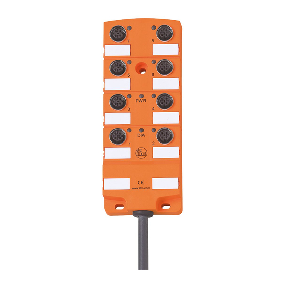
All manuals and user guides at all-guides.com CR2011 AUSGANGS MODUL Bestimmungsgemäße Verwendung / Funktion Das Ausgangsmodul CR2011 dient zur dezentralen Ansteuerung von Aktoren und Proportionalventilen. Über die integrierte Strommessung kann der Spulen- strom überwacht und zur Regelung genutzt werden. • Das Modul unterstützt binäre und analoge Ausgänge und wird daher in die Geräteklasse „I/O Modul“... -
Seite 4: Technische Daten
All manuals and user guides at all-guides.com CR2011 AUSGANGS MODUL Technische Daten Gehäuse 8-fach Verteiler-Gehäuse aus speziellem PUR, mit eingebauter Elektronik vollvergossen Maße 152 x 60 x 25 mm ( L x B x H ) Geräteanschluß PUR/PVC-Kabel 2 m 2 x 1,5 mm (Betriebsspannung) / 3 x 0,5 mm (CAN-Bus) -
Seite 5: Maße
All manuals and user guides at all-guides.com CR2011 AUSGANGS MODUL Maße M12x1 Elektrischer Anschluß Zum Schutz des gesamten Systems (Verkabelung und E/A-Modul) sind die einzelnen Stromkreise mit max. 16 A abzusichern. Anschlußbelegung Adernfarbe Potential 10 ... 30 V DC Betriebsspannung schwarz weiß... -
Seite 6: Kenndaten Der Ein-/Ausgänge
All manuals and user guides at all-guides.com CR2011 AUSGANGS MODUL Kenndaten der Ausgänge Digital-Ausgänge 8 Halbleiterausgänge; kurzschluß- und überlastfest. Schaltspannung 10 ... 30 V DC Schaltstrom max. 2 A (mit Stromüberwachung) max. 4 A (ohne Stromüberwachung) Summenstrom max. 16 A Stromüberwachung von jeweils 2 Kanälen über die Anschlüsse wählbar, dabei sind folgende Kanäle zusammengefasst: 1+2, 3+4, 5+6, 7+8 PWM-Ausgänge... -
Seite 7: Betriebsanzeigen
All manuals and user guides at all-guides.com CR2011 AUSGANGS MODUL Wertebereich -2000 ... +2000 mA Werte > +2000 mA werden auf +2000 mA abgerundet. < -2000 mA werden auf -2000 mA aufgerundet. 0 ... +100 mA werden auf +100 mA gerundet, -100 ... -
Seite 8: Parameter- Und Emcy-Objekt-Übersicht
All manuals and user guides at all-guides.com CR2011 AUSGANGS MODUL Parameter- und EMCY-Objekt-Übersicht Über die Funktion „Restore“ (s. Objektverzeichnis, Index 1011) können die Para- meter (Ausnahme Baudrate und Node-ID) mit den werkseitig hinterlegten Default-Werten belegt werden. Diese sind dann nach dem nächsten Einschalten der Versorgungsspannung gültig. - Seite 9 All manuals and user guides at all-guides.com CR2011 AUSGANGS MODUL EMCY Objekt Folgende Fehlercodes gemäß DSP-401 bzw. DSP-301 werden unterstützt: EMCY Zusatz Error Reg Beschreibung Code code 0x5000 0x81 0x00 Ein Kanal oder mehrere Kanäle nicht kalibriert. „Internal Software“: 0x6100 0x11 0x00 - Überlauf einer Rx-Queue;...
-
Seite 10: Objektverzeichnis
All manuals and user guides at all-guides.com CR2011 AUSGANGS MODUL Objektverzeichnis Herstellerspezifische Profile; Index 2000 bis 5FFF Index S-Idx Name Default Beschreibung 2000 u8, ro 0x04 Anzahl der Einträge Konfiguration = Anzahl der I/O Kanäle Ausgangskanal u8, rw 0x02 Konfiguration Kanalpaar 1/2* 1/2* 0 = AUS 2 = Binärausgang... - Seite 11 All manuals and user guides at all-guides.com CR2011 AUSGANGS MODUL Herstellerspezifische Profile; Index 2000 bis 5FFF Index S-Idx Name Default Beschreibung 20F0 Einstellung u8, rw 0x20 Node ID unter dem das Modul im Node ID (= 32) CANopen Netz angesprochen wird 20F1 Einstellung u8, rw...
-
Seite 12: Objektverzeichnis
All manuals and user guides at all-guides.com CR2011 AUSGANGS MODUL Objektverzeichnis Kommunikationsprofile; Index 1000 bis 1FFF Index S-Idx Name Default Beschreibung 1000 device type u32, ro 0xF0191 Prof. 401; Ausgänge, binär und analog 1001 error register u8, ro 0x00 Bitcodiert gemäß Prof301; unterstützt wird: 0b 0000 0000 kein Fehler 0b 0000 0001 generic error... - Seite 13 All manuals and user guides at all-guides.com CR2011 AUSGANGS MODUL Kommunikationsprofile; Index 1000 bis 1FFF Index S-Idx Name Default Beschreibung 100D life time factor u8, rw 0x00 Wenn für "guard time" * "life time" kein "node guarding" empfangen wird, generiert das Modul ein EMCY. Das Produkt aus "guard time"...
- Seite 14 All manuals and user guides at all-guides.com CR2011 AUSGANGS MODUL Objektverzeichnis Kommunikationsprofile; Index 1000 bis 1FFF Index S-Idx Name Default Beschreibung 1401 Receive u8, ro 0x02 Anzahl der Einträge Rec PDO 2; PDO 2 Analogausgänge COB ID u32, rw 0x300 + - PDO ist gültig (Bit 31 = 0) Node ID - CAN ID des 2.
- Seite 15 All manuals and user guides at all-guides.com CR2011 AUSGANGS MODUL Kommunikationsprofile; Index 1000 bis 1FFF Index S-Idx Name Default Beschreibung 1800 Trans PDO 1 u8, ro 0x02 Anzahl der Einträge Trans PDO 1; Strom-Istwerte COB ID u32, rw 0x180 + - PDO ist gültig (Bit 31 = 0) Node ID - CAN ID des 1.
-
Seite 16: Programmierung (Ecolog 100 Plus )
All manuals and user guides at all-guides.com CR2011 AUSGANGS MODUL Programmierung plus (ecolog 100 Allgemeines Das E/A-Modul muß als CANopen-Slave mit den CANopen-Startfunktionen „COP_MSTR_BOOTUP“ und „COP_MSTR_MAIN“ vom R 360-Master initialisiert und in den Zustand „OPERATIONAL“ versetzt werden (LED blinkt grün; 2 Hz). Programmier-Funktion Wird die Funktion „CR2011“... - Seite 17 Wertzuweisung enthalten sein. Im Programmablauf kann der Zugriff auf eine Strukturkomponente z.B. wie dar- gestellt erfolgen. plus Screenshot der ecolog 100 Programmieroberfläche plus Weitere ecolog 100 Programmierbeispiele für das E/A-Modul erhalten Sie auf Nachfrage von der ifm electronic gmbh. EITE...
-
Seite 18: Funktion
All manuals and user guides at all-guides.com CR2011 AUSGANGS MODUL Funktion: CR2011 CR2011 Library: CR2011_C.lib ENABLE CFG_RESULT INIT IO_RCV Zweck: Parametriert und liest NODE_ID die Konfigurations- und E/A-Daten CFG_READ des Ein-/Ausgangs-Moduls CFG_WRITE CR2011 CFG_DATA RX_TYPE TX_TYPE SYNC IO_DATA Parameter Name Datentyp Beschreibung Eingänge... - Seite 19 All manuals and user guides at all-guides.com CR2011 AUSGANGS MODUL Datenstruktur: TYPE CR2011 ConfigStruct CR2011 ConfigStruct STRUCT GUARDTIME: TIME; Zweck: LIFETIME: BYTE; Parameter- und Konfigurationsdaten Ch1_2: BYTE; können geschrieben oder gelesen werden. Ch3_4: BYTE; Ch5_6: BYTE; Die Datenstruktur wird dem Funktions- Ch7_8: BYTE;...
- Seite 20 All manuals and user guides at all-guides.com CR2011 AUSGANGS MODUL Datenstruktur: TYPE CR2011 InOutStruct CR2011 InOutStruct STRUCT BinOut1: BOOL; Zweck: BinOut2: BOOL; Aktuelle E/A-Daten werden gelesen BinOut3: BOOL; BinOut4: BOOL; bzw. geschrieben. BinOut5: BOOL; Die Datenstruktur wird dem Funktions- BinOut6: BOOL; BinOut7: BOOL;...
-
Seite 21: Wartung, Instandsetzung Und Entsorgung
All manuals and user guides at all-guides.com CR2011 AUSGANGS MODUL Wartung, Instandsetzung und Entsorgung Da innerhalb des Moduls keine vom Anwender zu wartenden Bauteile enthalten sind, darf das Gehäuse nicht geöffnet werden. Die Instandsetzung des Moduls darf nur durch den Hersteller durchgeführt werden. Die Entsorgung muß... -
Seite 22: Begriffe Und Abkürzungen
All manuals and user guides at all-guides.com CR2011 AUSGANGS MODUL Begriffe und Abkürzungen 0b ... binärer Zahlenwert (zur Bitcodierung), z.B. 0b0001 0000 0x ... hexadezimaler Zahlenwert, z.B. 0x64 (= 100 dezimal) Baudrate Übertragungsgeschwindigkeit (1 Baud = 1 Bit/sec.) CAN Application Layer CAN basierendes Netzwerkprotkoll auf Applikationsebende Controller Area Network (Bussystem für den Einsatz im Mobilbereich) CAN_H... - Seite 23 All manuals and user guides at all-guides.com CR2011 AUSGANGS MODUL Node-ID Knotenpunkt-Identifier (Kennung eines Teilnehmers im CANopen Netz) Objekt (auch OBJ) Oberbegriff für austauschbare Daten/Botschaften innerhalb des CANopen- Netzwerks Objektverzeichnis enthält alle CANopen-Kommunikationsparameter eines Gerätes, sowie gerä- tespezifische Parameter und Daten. Auf die einzelnen Einträge wird über den Index und S-Index zugegriffen.
-
Seite 24: Safety Instructions
All manuals and user guides at all-guides.com CR2011 OUTPUT MODULE Safety instructions This description is part of the unit. It contains texts and drawings concerning the correct handling of the controller and must be read before installation or use. Observe the information of the description. Non-observance of the notes, operation which is not in accordance with use as prescribed below, wrong installation or handling can result in serious harm concerning the safety of people and plant. -
Seite 25: Function And Features
All manuals and user guides at all-guides.com CR2011 OUTPUT MODULE Function and features The CR2011 output module enables decentralised triggering of actuators and proportional valves. The coil current can be monitored and controlled via the inte- grated current measurement. • The module supports binary and analog outputs and is therefore classified in the device profile "I/O module"... -
Seite 26: Technical Data
All manuals and user guides at all-guides.com CR2011 OUTPUT MODULE Technical data Housing 8-channel splitter box made of special PUR with integrated elec- tronics, fully potted Dimensions 152 x 60 x 25 mm (L x W x H) Device connection PUR/PVC cable 2 m, 2 x 1.5mm²... -
Seite 27: Dimensions
All manuals and user guides at all-guides.com CR2011 OUTPUT MODULE Dimensions M12x1 Electrical connection To protect the whole system (wiring and output module) the individual elec- tric circuits must be protected with max. 16A. Wiring core colour potential 10 ... 30 V DC Operating voltage black white... -
Seite 28: Characteristics Of The Inputs/Outputs
All manuals and user guides at all-guides.com CR2011 OUTPUT MODULE Characteristics of the outputs Digital outputs 8 semi-conductor outputs, short-circuit and overload protection switching voltage 10 ... 30 V DC switching current max. 2 A (with current monitoring) max. 4 A (without current monitoring) total current max. -
Seite 29: Operating Indicators (Status Led)
All manuals and user guides at all-guides.com CR2011 OUTPUT MODULE value range -2000 ... +2000 mA values > +2000 mA are rounded to +2000 mA < -2000 mA are rounded to -2000 mA 0 ... +100 mA are rounded to +100 mA, -100 ... -
Seite 30: Parameter And Emcy Object Overview
All manuals and user guides at all-guides.com CR2011 OUTPUT MODULE Parameter and EMCY object overview With the function "restore" (see object directory, index 1011) the parameters (except the baud rate and the node ID) can be assigned to the factory default val- ues. - Seite 31 All manuals and user guides at all-guides.com CR2011 OUTPUT MODULE EMCY Object The following error codes to DSP-401 and DSP-301 are supported: EMCY Error Additional Description code code 0x5000 0x81 0x00 One channel or several channels not calibrated "Internal software": 0x6100 0x11 0x00...
-
Seite 32: Object Directory
All manuals and user guides at all-guides.com CR2011 OUTPUT MODULE Object directory Manufacturer Specific Profile Area; index 2000 to 5FFF Index S-idx Designation Type Default Description Number of the entries u8, ro 0x04 Configuration (= number of the output channels) 0 = OFF Output 2 = binary output... -
Seite 33: Object Directory
All manuals and user guides at all-guides.com CR2011 OUTPUT MODULE Object directory Manufacturer Specific Profile Area; index 2000 to 5FFF Index S-idx Designation Type Default Description Setting of the 0x20 20F0 u8, rw The node ID used to access the output Node ID (= 32) module in the CANopen network. -
Seite 34: Communication Profile Area; Index 1000 To 1Fff
All manuals and user guides at all-guides.com CR2011 OUTPUT MODULE Object directory Communication Profile Area; index 1000 to 1FFF Index S-idx Designation Type Default Description Profile 401 1000 Device Type u32, ro 0xF0191 outputs, binary and analog Bit-coded to profile 301, the following is sup- ported: 0b0000 0000 no error... - Seite 35 All manuals and user guides at all-guides.com CR2011 OUTPUT MODULE Object directory Communication Profile Area; index 1000 to 1FFF Index S-idx Designation Type Default Description If no "node guarding" is received for "guard time" x "life time", the output module switches Life Time 100D u8, rw...
- Seite 36 All manuals and user guides at all-guides.com CR2011 OUTPUT MODULE Object directory Communication Profile Area; index 1000 to 1FFF Index S-idx Designation Type Default Description Receive Number of the entries receive PDO2 u8, ro 0x02 PDO 2 Analog outputs 0x300 - PDO is valid (bit 31 = 0) COB ID u32, rw...
- Seite 37 All manuals and user guides at all-guides.com CR2011 OUTPUT MODULE Object directory Communication Profile Area; index 1000 to 1FFF Index S-idx Designation Type Default Description Transmit Number of the entries transmit PDO1, (actual u8, ro 0x02 PDO 1 current values) 0x180 - PDO is valid (bit 31 = 0) COB ID...
-
Seite 38: Programming (Ecolog 100 Plus )
All manuals and user guides at all-guides.com CR2011 OUTPUT MODULE Programming plus (ecolog 100 General The I/O module must be initialised as CANopen slave with the CANopen start functions "COP_MSTR_BOOTUP" and "COP_MSTR_MAIN" by the R 360 master and set to the state "OPERATIONAL" (LED flashes green, 2 Hz). Programming function If the function "CR2011"... - Seite 39 In the program access to a structure component can be represented as follows: plus Screen shot of the ecolog 100 programming platform plus More ecolog 100 programming examples of the I/O module CR2011 can be obtained from ifm electronic gmbh upon request. PAGE...
- Seite 40 All manuals and user guides at all-guides.com CR2011 OUTPUT MODULE Function: CR2011 CR2011 Library: CR2011_C.lib ENABLE CFG_RESULT INIT IO_RCV Purpose: Sets parameters and reads NODE_ID the configuration and I/O data CFG_READ of the input/output module CFG_WRITE CR2011 CFG_DATA RX_TYPE TX_TYPE SYNC IO_DATA Parameter...
-
Seite 41: Structure Components
All manuals and user guides at all-guides.com CR2011 OUTPUT MODULE Data structure: TYPE CR2011 ConfigStruct CR2011 ConfigStruct STRUCT GUARDTIME: TIME; Purpose: LIFETIME: BYTE; Parameter and configuration data Ch1_2: BYTE; can be written or read. Ch3_4: BYTE; Ch5_6: BYTE; The data structure is assigned to the Ch7_8: BYTE;... - Seite 42 All manuals and user guides at all-guides.com CR2011 OUTPUT MODULE Data structure: TYPE CR2011 InOutStruct CR2011 InOutStruct STRUCT BinOut1: BOOL; Purpose: BinOut2: BOOL; The current I/O data of the module BinOut3: BOOL; BinOut4: BOOL; are read or written. BinOut5: BOOL; The data structure is assigned to the BinOut6: BOOL;...
-
Seite 43: Maintenance, Repair And Disposal
All manuals and user guides at all-guides.com CR2011 OUTPUT MODULE Maintenance, repair and disposal As the input/output module does not contain any components which must be maintained by the user, the housing must not be opened. The maintenance of the module may only be carried out by the manufacturer. The disposal must be carried out according to the corresponding national envi- ronmental regulations. -
Seite 44: Terms And Abbreviations
All manuals and user guides at all-guides.com CR2011 OUTPUT MODULE Terms and abbreviations 0b ... binary value (for bit coding), e.g. 0b0001 0000 0x ... hexadecimal value, e.g. 0x64 (= 100 decimal) Baudrate transmission speed (1 baud = 1 bit/s) CAN Application Layer CAN-based network protocol on application level Controller Area Network (bus system for use in mobile applications) - Seite 45 All manuals and user guides at all-guides.com CR2011 OUTPUT MODULE Object (also OBJ) term for data/messages which can be exchanged in the CANopen network Object directory contains all CANopen communication parameters of a device as well as device-specific parameters and data Access to the individual entries is possible via the index and S index.
-
Seite 46: Notizen
All manuals and user guides at all-guides.com CR2011 OUTPUT MODULE Notizen / Notes PAGE... - Seite 47 All manuals and user guides at all-guides.com CR2011 OUTPUT MODULE PAGE...
- Seite 48 All manuals and user guides at all-guides.com...