Herunterladen Inhalt Inhalt Diese Seite drucken

Werbung

Verfügbare Sprachen

Verfügbare Sprachen

Montageanleitung
Installation Instructions
Notice de Montage
AS-i Modul
AS-i module
Module AS-i
AC2616
AC2617

Werbung

Inhaltsverzeichnis
loading

Inhaltszusammenfassung für IFM Electronic AC2616

  • Seite 1 Montageanleitung Installation Instructions Notice de Montage AS-i Modul AS-i module Module AS-i AC2616 AC2617...
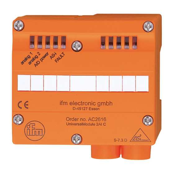
  • Seite 2: Bestimmungsgemäße Verwendung

    Datenverkehr im AS-i Netz. Die Datenübertragung zum Host erfolgt asynchron nach dem AS-i Profil S-7.3, gemäß AS-i Spezifikation V2.1. • Strommessung 4...20 mA (AC2616) oder Spannungsmessung 0...10 V (AC2617) • AS-i Profil S-7.3.D • Der Anschluss der Messwertgeber erfolgt über Käfigzugfederklemmen •...
  • Seite 3: Montage

    Montage Wenn Sie Modulunterteile ohne Adressierbuchse verwenden (AC5000 oder AC5003) verwenden, adressieren Sie zunächst das Modul, indem Sie es auf ein Adressiergerät (AC1154) setzen und eine freie Adresse zwischen 1 und 31 vergeben. Setzen Sie Modulunterteile mit Adressierbuchse (AC5010, AC5011) ein, so können die Module zu einem späteren Zeitpunkt mit dem Adressieradapter E70213 adressiert werden.
  • Seite 4 COM1/2 Anschluss eines 3-Draht-Sensors Analogmodul 3-Draht Sensor Ein 3-Draht-Sensor wird über die Klemmen I+, I- und C1/2 (AC2616) bzw. V1/2 (AC2617) angeschlossen. Die Klemmen I- und COM1/2 müs- C1/2 (AC2616) V1/2 (AC2617) sen über eine Brücke miteinander verbunden sein.
  • Seite 5 Versorgung PELV benötigt ohne Erdanbindung Das Analogeingangsmodul mit 2 Stromeingängen (AC2616) ist im Auslieferungszustand zwischen den Klemmen I+ und C2 mit einem Widerstand und zwischen den Klemmen I- und COM2 mit einer Brücke bestückt. Dadurch wird bei der Inbetriebnahme des Moduls mit nur einem angeschlossenem Sensor keine Fehler- meldung vom Modul angezeigt.
  • Seite 6 Betrieb AC2616 Prüfen Sie, ob das Gerät sicher funktioniert. Anzeige durch LEDs: • LEDs gelb (Analog 1 / 2) leuchten: analoges Signal im Messbereich LEDs gelb (Analog 1 / 2) blinken: analoges Signal außerhalb des Messbereichs LEDs gelb (Analog 1 / 2) aus:...
  • Seite 7 Analog 1 oder Analog 2 außerhalb des Wertebereiches ist. Messbereich der Analogeingangsmodule: Die Messbereiche, das Verhalten der LEDs und deren Bedeutung ent- nehmen Sie bitte den folgenden Tabellen: Analogeingangsmodul 2E, 4 ... 20 mA - AC2616 Bereich Einheiten Einheiten Bedeutung 4...20 mA...
  • Seite 8 Analogeingangsmodul 2E, 0 ... 10 V - AC2617 Bereich Einheiten Einheiten Bedeutung 0...10 V dez. hex. Analog < 0 V 0000 0000 Unterlauf 0 ... 10 V 0000 ... 10000 0000 ... 2710 Nennbereich 10,001 V ... 10001 ... 11500 2711 ...
  • Seite 9: Function And Features

    AS-i network. The data transfer to the host is asynchronous according to the AS-i profile S-7.3 and the AS-i specification V2.1. • Current measurement 4...20 mA (AC2616) or voltage measurement 0...10 V (AC2617) • AS-i profile S-7.3.D •...
  • Seite 10: Installation

    Installation When you use module lower parts without addressing socket (AC5000 or AC5003) first address the module by placing it onto an addressing unit (AC1154) and assign a free address between 1 and 31. When you use module lower parts with an addressing socket (AC5010, AC5011) the modules can be addressed with the addressing adapter E70213 later on.
  • Seite 11 Electrical connection Connection of a 2-wire sensor analogue module 2-wire sensor A 2-wire sensor is connected via the terminals I+ and C1/2 (AC2616) or V1/2 (AC2617). C1/2 (AC2616) The terminals I- and COM1/2 must V1/2 (AC2617) be connected to each other via a link.
  • Seite 12 When the analogue input module with 2 current inputs (AC2616) is delivered a resistor is placed between the terminals I+ and C2 and a link between the terminals I- and COM2 so that no error message is indicated by the module when it is operated with only one sensor being connected.
  • Seite 13 Operation AC2616 Check the safe functioning of the unit. Display by LEDs: • LEDs yellow (analog 1 / 2) on: analogue signal in the measuring range LEDs yellow (analog 1 / 2) flashing: analogue signal outside the measuring range LEDs yellow (analog 1 / 2) out:...
  • Seite 14 Measuring range of the analogue input modules: For the measuring ranges, the LED states and their meaning please see the following tables: Analogue input module 2I, 4...20 mA - AC2616 Range Units Units Meaning 4 ...
  • Seite 15 Analogue input module 2I, 0 ... 10 V - AC2617 Range Units Units Meaning 0 ... 10V dec. hex. analog < 0 V 0000 0000 outside range 0 ... 10 V 0000 ... 10000 0000 ... 2710 nominal range 10.001 V ... 10001 ...
  • Seite 16: Fonctionnement Et Caractéristiques

    AS-i. La transmission des données à l'hôte est asynchrone selon le profil AS-i S-7.3, selon la spécification AS-i V2.1. • mesure de courant 4...20 mA (AC2616) ou mesure de tension 0...10 V (AC2617) • profil AS-i S-7.3.D •...
  • Seite 17: Raccordement Électrique

    Montage Pour l'emploi d'embases de câblage sans prise d'adressage (AC5000 ou AC5003), adresser d'abord le module en le raccordant à une unité d'adressage (AC1154) et en affectant une adresse libre entre 1 et 31. Pour l'emploi d'embases de câblage avec prise d'adressage (AC5010, AC5011), les modules peuvent être adressés ultérieurement par le cor- don d'adressage E70213.
  • Seite 18 Raccordement électrique Raccordement d'un capteur 2 fils Module analogique Capteur 2 fils Un capteur 2 fils est raccordé via les bornes I+ et C1/2 (AC2616) ou V1/2 (AC2617). C1/2 (AC2616) Les bornes I- et COM1/2 doivent V1/2 (AC2617) être reliées via un shunt.
  • Seite 19 à la terre A la livraison le module d'entrées analogiques avec 2 entrées courant (AC2616) est fourni avec une résistance entre les bornes I+ et C2 et un shunt entre les bornes I- et COM2 pour éviter un message d'erreur du module si un seul capteur est raccordé lors de la mise en service du module.
  • Seite 20 Fonctionnement AC2616 Vérifier le bon fonctionnement de l'appareil. Affichage par LED: • LED jaune (analog 1 / 2) allumée: signal analogique dans la plage de mesure LED jaune (analog 1 / 2) clignotant: signal analogique en dehors de la plage de mesure LED jaunes (analog 1 / 2) éteintes : aucun capteur raccordé...
  • Seite 21 à au moins une voie analogique. Plage de mesure des modules d'entrées analogiques: Pour les plages de mesure, le comportement des LED et leur significa- tion voir les tableaux suivants: Module d'entrées analogiques 2E, 4...20 mA - AC2616 Plage Unités Unités Signification 4...20 mA...
  • Seite 22 Module d'entrées analogiques 2E, 0...10 V - AC2617 Plage Unités Unités Signification 0...10 V déc. hex. analog en dehors de la < 0 V 0000 0000 allumée plage admissible 0...10 V 0000 ... 10000 0000 ... 2710 allumée plage nominale 10,001 V ...

Diese Anleitung auch für:

Ac2617

Inhaltsverzeichnis