Comfee MSR23 Serie Installationshandbuch
Split-raumklimaanlage
Inhaltsverzeichnis
Verfügbare Sprachen
Verfügbare Sprachen
SPLIT-TYPE ROOM AIR CONDITIONER
Installation Manual
Forest Series
All Model Numbers
MSAF5-09HRDN1-QE-IU
MSAF5-12HRDN1-QE-IU
MSAF5-18HRDN1-QE-IU
IMPORTANT NOTE:
Read this manual carefully before installing
or operating your new air conditioning
unit. Make sure to save this manual for
future reference.
Kapitel
Inhaltsverzeichnis

Verwandte Anleitungen für Comfee MSR23 Serie


Inhaltszusammenfassung für Comfee MSR23 Serie
-
Seite 33: Msr23-Serie Af Mit Qc
SPLIT-RAUMKLIMAANLAGE Installationshandbuch MSR23-Serie AF mit QC Alle Modellnummern MSAF5-09HRDN1-QE-IU MSAF5-12HRDN1-QE-IU MSAF5-18HRDN1-QE-IU WICHTIGER HINWEIS: Lesen Sie dieses Handbuch sorgfältig, bevor Sie Ihre neue Klimaanlage installieren oder betreiben. Bewahren Sie dieses Handbuch für später gut auf. - Seite 34 Inhaltsverzeichnis Installationshandbuch 0 Sicherheitsvorkehrungen ......1 Zubehör ............... 2 Installationsüberblick - Inneneinheit ....3 Teile der Anlage ..........4 Installation der Inneneinheit ..Auswahl des Installationsortes ....Wandbefestigung der Montageplatte ..Loch für Verbindungsleitungen bohren ..Kältemittelleitungen vorbereiten ....Ablaufschlauch anschließen ....... Signalkabel verbinden ........
- Seite 35 6 Kältemittelleitungen ........Kältemittelleitungen verbinden ........7 Elektro- und Gasdichtheitsprüfungen ..8 Testlauf ..............9 Europäische Richtlinien zur Entsorgung 31...
-
Seite 36: Sicherheitsvorkehrungen
Sicherheitsvorkehrungen Lesen Sie die Sicherheitsvorkehrungen vor der Installation Eine fehlerhafte Installation durch Nichtbeachtung der Anweisungen kann zu schweren Schäden oder zur Verletzung führen. Die Schwere möglicher Schäden oder Verletzungen ist als WARNUNG oder VORSICHT klassifiziert. Dieses Symbol zeigt an, dass eine Nichtbeachtung der Anweisungen zu schweren Verletzungen oder zum Tode führen kann. - Seite 37 WARNUNG Beachten Sie bei allen Elektroarbeiten die örtlichen und nationalen Schaltungsvorschriften, Vorgaben und das Installationshandbuch. Zur Stromversorgung müssen Sie einen separaten Stromkreis und eine Einzelsteckdose verwenden. Schließen Sie keine weiteren Geräte an dieser Steckdose an. Unzureichende elektrische Leistung oder Schäden an der Elektrik können zum elektrischen Schlag oder Brand führen.
- Seite 38 Zubehör Die Klimaanlage wird mit folgendem Zubehör geliefert. Verwenden Sie sämtliche Installations- und Zubehörteile für die Montage der Klimaanlage. Eine fehlerhafte Installation kann zum Wasseraustritt, elektrischen Schlag und Brand führen oder die Ausrüstung herunterfallen lassen. Name Form Menge Montageplatte Klemmanker Befestigungsschrauben der Montageplatte ST3.9 X 25 Fernbedienung...
-
Seite 39: Anleitung Fernbedienung
Name Form Menge INVERTER-SPLITT-RAUMKLIMAANLAGE Bedienhandbuch Aurora Baureihe Alle Modelle Bedienhandbuch WICHTIGER HINWEIS: Lesen Sie dieses Handbuch sorgfältig, bevor Sie Ihre neue Klimaanlage installieren oder betreiben. Bewahren Sie dieses Handbuch für später gut auf. INVERTER-SPLITT-RAUMKLIMAANLAGE Installationshandbuch Aurora Baureihe Installationshandbuch Alle Modelle WICHTIGER HINWEIS: Lesen Sie dieses Handbuch sorgfältig, bevor Sie Ihre neue... -
Seite 40: Installationsüberblick - Inneneinheit
Installationsüberblick - Inneneinheit 15cm (5,9 Zoll) 12cm 12cm (4,75 Zoll) (4,75 Zoll) 2,3m (90,55 Zoll) Auswahl des Installationsortes Bestimmen der Wandlochposition (Seite 11) (Seite 12) Anbringen der Montageplatte Wand Loch bohren (Seite 12) (Seite 12) Seite 8 ... - Seite 41 Leitungen verbinden Kabel verbinden Ablaufschlauch (Seite 15) (Seite 19) vorbereiten (Seite 17) Leitungen und Kabel umwickeln (Seite 20) Inneneinheit montieren (Seite 20) Seite 9 ...
-
Seite 42: Teile Der Anlage
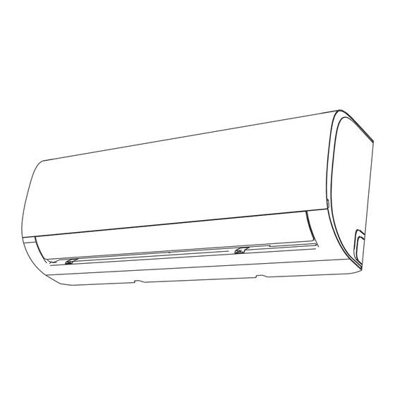
Teile der Anlage Wandmontageplatte Frontplatte Netzkabel (manche Anlagen) Luftleit- Ablaufleitung lamelle Signalkabel Kältemittelleitungen Fernbedienung Fernbedienungshalterung (optional) Außeneinheit Netzkabel (manche Anlagen) Abb. 3.1 HINWEIS ZU DEN ABBILDUNGEN Die Abbildungen in diesem Handbuch dienen nur zur Veranschaulichung. Die tatsächliche Form Ihrer Inneneinheit kann sich geringfügig davon unterscheiden. Die tatsächliche Form soll dominieren. ... -
Seite 43: Auswahl Des Installationsortes
Installation der Inneneinheit Installieren Sie die Anlage NICHT an folgenden Installationsanweisungen – Orten: Inneneinheit In der Nähe von Hitze, Dampf oder brennbaren Gasen VOR DER INSTALLATION In der Nähe brennbarer Dinge wie Prüfen Sie vor der Installation der Inneneinheit Vorhänge oder Kleidung das Etikett auf dem Produktkarton, damit die In der Nähe von Hindernissen, die die Modellnummern der Inneneinheit und... -
Seite 44: Wandbefestigung Der Montageplatte
Beachten Sie folgende Zeichnung für die richtigen Abstände zu Wänden und der Decke: 15cm (5,9 Zoll) oder mehr 12cm (4,75 Zoll) 12cm (4,75 Zoll) oder mehr oder mehr Abb. 4.1 2,3m (90,55 Zoll) oder mehr Schritt 2: Wandbefestigung der Montageplatte Schritt 3: Wandbohrung für Verbindungsleitungen bohren Auf der Montageplatte befestigen Sie später... - Seite 45 398mm (15,67 Zoll) Wand 233,1mm (9,17 Zoll) 146,5mm (5,76 Zoll) Innen Außen Umriss der Inneneinheit Wand links hinten Wandloch rechts Loch 65mm (2,5 Zoll) 115.6 mm (4,55 Zoll) 117,5mm (4,62 Zoll) 45mm (1,7 Zol l ) 101,6mm (4 Zoll ) hinten 65mm (2,5 Zoll) 715mm (28 Zoll) Modell A...
- Seite 46 Stellen Sie unbedingt sicher, dass kein Schritt 4: Kältemittel in die Umwelt gelangt. Die Kältemittelleitungen befinden sich in einem Unsachgemäßer Umgang mit Kältemittel führt Isolierschlauch und sind hinten an der Einheit Ihnen und der Umwelt Schaden zu. Tragen Sie angebracht.
-
Seite 47: Kältemittelleitungen An Der Inneneinheit Anschließen
4.3 Kältemittelleitungen an der Inneneinheit anschließen Die Schutzkappen am Gerät und an der Leitung erst unmittelbar vor dem Herstellen der Verbindung entfernen. Die Kältemittelleitungen ordentlich ausrollen, stellen Sie sicher das die Quick- Verschraubungen die gleichen Dimensionen haben. Setzen Sie die Quick- Verschraubungen der Leitung an den Anschluss am Innengerät an und ziehen Abb. - Seite 48 Nachdem Sie die Quick-Verschraubungen Bündeln Sie die Kältemittelleitungen und isolieren Sie sie mit geeignetem Klebeband, z. verbunden haben stecken Sie die B. geschlossenzelligem Kautschukband. Siehe Kältemittelleitungen und die Abb. 4.13 Kondensatleitung durch die Wandöffnung. Siehe Abb. 4.10 HINWEIS: Die Quick-Verschraubungen müssen außerhalb des Zimmers angeordnet sein.
-
Seite 49: Ablaufschlauch Anschließen
Schritt 5: Ablaufschlauch anschließen VERSCHLIESSEN DES UNBENUTZTEN ABLAUFLOCHS Standardmäßig ist der Ablaufschlauch links an Um unerwünscht Lecks zu vermeiden, müssen Sie der Einheit angeschlossen (wenn Sie von hinten das nicht verwendete Ablaufloch mit dem auf die Einheit schauen). Er kann jedoch auch mitgelieferten Gummistopfen verschließen. - Seite 50 LESEN SIE DIESE VORSCHRIFTEN, BEVOR SIE ELEKTROARBEITEN AUSFÜHREN 1. Alle Elektroarbeiten müssen den lokalen und nationalen Schaltungsvorschriften entsprechen und von einem zugelassenen Elektriker ausgeführt werden. 2. Alle elektrischen Anschlüsse müssen gemäß dem Elektrischen Schaltplan erfolgen, der sich an den Seitenwänden der Innen- und Außeneinheit befindet. 3.
-
Seite 51: Signalkabel Verbinden
BEACHTEN SIE DIE SPEZIFIKATIONEN DER SICHERUNG Schritt 6: Signalkabel verbinden Die Platine (PCB) der Klimaanlage hat eine Das Signalkabel sorgt für die Kommunikation Sicherung zum Schutz vor zu hohen Stromstärken. zwischen Innen- und Außeneinheit. Zuerst müssen Die Spezifikationen der Sicherung sind auf der Sie die richtige Kabelgröße wählen und es dann für Platine aufgedruckt, etwa: T3.15A/250VAC, die Verbindung vorbereiten. -
Seite 52: Leitungen Und Kabel Umwickeln
6. Führen Sie das Signalkabel durch diesen Schlitz VERDRILLEN SIE DAS SIGNALKABEL NICHT von der Rückseite der Einheit nach vorne. MIT ANDEREN KABELN 7. Von der Vorderseite der Einheit gesehen Beim Bündeln dieser Dinge verdrillen oder bringen Sie die farbigen Kabel mit den kreuzen Sie das Signalkabel nicht mit Etiketten am Anschlussblock zusammen, irgendwelchen anderen Kabeln. -
Seite 53: Installation Der Außeneinheit
Installation der Außeneinheit Installationsanweisungen – Außeneinheit Schritt 1: Auswahl des Installationsortes Vor der Installation der Außeneinheit müssen Sie einen geeigneten Montageort wählen. Folgende Standards helfen Ihnen bei der Auswahl des geeigneten Montageortes für die Anlage. Geeignete Installationsorte müssen folgende Standards erfüllen: ... -
Seite 54: In Kalten Klimaregionen
Falls der Ablaufanschluss mit einer Gummidichtung BESONDERE BETRACHTUNGEN FÜR EXTREME versehen ist (siehe Abb. 4.4 - A ), machen Sie WETTERSITUATIONEN folgendes: Falls die Einheit starkem Wind ausgesetzt ist: Passen Sie die Gummidichtung auf das Ende des Montieren Sie die Einheit so, dass sich der Luftauslass- Ablaufanschlusses für die Verbindung zur Außeneinheit lüfter im Winkel von 90°... - Seite 55 Schritt 3: Außeneinheit verankern Die Außeneinheit kann am Boden oder an einer Wandhalterung verankert werden. MONTAGEMAßE DER EINHEIT Lufteinlass Folgende Liste zeigt die Maße Lufteinlass verschiedener Außeneinheiten sowie den Abstand zwischen ihren Montagefüßen. Bereiten Sie die Installationsbasis der Luftauslass Einheit gemäß nachstehender Abmessungen vor.
- Seite 56 Wenn Sie die Einheit auf eine Wandhalterung VOR DER AUSFÜHRUNG VON montieren wollen, machen Sie folgendes: ELEKTROARBEITEN LESEN SIE BITTE DIESE VORSCHRIFTEN VORSICHT Alle Elektroarbeiten müssen den lokalen und nationalen Schaltungsvorschriften entsprechen und Prüfen Sie vor der Wandmontage einer Einheit, von einem zugelassenen Elektriker ausgeführt dass die Wand aus Mauerstein, Beton oder werden.
- Seite 57 ACHTEN SIE AUF DEN STROMFÜHRENDEN DRAHT WARNUNG Achten Sie beim Klemmen darauf, den stromführenden BEVOR SIE IRGENDWELCHE ELEKTROARBEITEN Live ("L") Draht klar von den anderen zu unterscheiden. AUSFÜHREN, SCHALTEN SIE DEN HAUPTSCHALTER DES SYSTEMS AUS. WARNUNG 1. Bereiten Sie die Kabel für die Verbindung vor: DIE SCHALTUNG MUSS EXAKT NACH DEM SCHALTPLAN INNEN AUF DER VERWENDEN SIE DIE RICHTIGEN KABEL...
- Seite 58 Kältemittelleitungen verbinden Kältemittelleitung mit dem Außengerät verbinden ACHTUNG: Zu Ihrer eigenen Sicherheit tragen Sie jederzeit Schutzhandschuhe und eine Schutzbrille. 3. Setzen Sie die ordentlich ausgerollte Leitung mit der Quick-Verschraubungen an den Anschluss am Die Abdeckung wie in Abb. 6.1 gezeigt Außengerät gerade ausgerichtet an.
- Seite 59 Rohrleistungs- Newtonmeter (Nm) durchmesser (mm) Sie die Innensechskantschraube mit dem 5mm 24-27 Innensechskantschlüssel bis zum Anschlag gegen 12,7 40-47 den Uhrzeigersinn drehen. Wenn das Ventil nicht 19,1 61-67 komplett geöffnet wird kann es zu Störungen 25,4 81-88 oder Schäden der Anlage führen. Montieren Sie Nachdem die Schritte 1-4 durchgeführt wurden wieder die Abdeckkappe und ziehen sie fest um und alle Anschlüsse verbunden wurden...
-
Seite 60: Elektrische Und Gasdichtheitsprüfungen
Elektrische und Gasdichtheitsprüfungen WARNING – GEFAHR DES Elektrosicherheitsprüfungen ELEKTRISCHEN SCHLAGS Nach der Installation kontrollieren Sie, dass alle elektrischen Anschlüsse gemäß den lokalen und ALLE ELEKTROARBEITEN MÜSSEN DEN LOKALEN nationalen Schaltungsvorschriften sowie UND NATIONALEN SCHALTUNGSVORSCHRIFTEN entsprechend diesem Installationshandbuch erfolgt ENTSPRECHEN UND VON EINEM ZUGELASSENEN sind. -
Seite 61: Vor Dem Testlauf
Testlauf Vor dem Testlauf Liste auszuführender Kontrollen ERFÜLLT/FEHLER Kein Kriechstrom Führen Sie den Testlauf erst aus, wenn Sie folgende Schritte abgeschlossen haben: Einheit ist vorschriftsmäßig geerdet • Elektrosicherheitsprüfungen – Bestätigen Sie, dass die elektrische Installation der Anlage Alle elektrischen Anschlüsse sind sicher ist und richtig funktioniert ordnungsgemäß... - Seite 62 PRÜFEN SIE NOCHMAL DIE LEITUNGSVERBINDUNGEN Im Betrieb steigt der Druck im Kältemittelkreislauf. Dabei könnten Undichtheiten auftreten, die bei der anfänglichen Dichtheitsprüfung noch nicht vorhanden waren. Nehmen Sie sich im Testlauf die Zeit und kontrollieren nochmal, dass alle Verbindungsstellen der Kältemittelleitungen dicht sind. Siehe den Abschnitt Gasdichtheitsprüfungen für Anweisungen dazu.
-
Seite 63: Europäische Richtlinien Zur Entsorgung
Europäische Richtlinien zur Entsorgung Dieses Gerät enthält Kältemittel und andere möglicherweise gefährliche Stoffe. Für die Entsorgung dieses Gerätes erfordert das Gesetz eine spezielle Sammlung und Aufarbeitung. Entsorgen Sie dieses Produkt nicht als allgemeinen Hausmüll oder kommunalen Müll. Für die Entsorgung dieses Gerätes haben Sie folgende Möglichkeiten: •... - Seite 64 Midea Europe GmbH Eisenstrasse 9c 65428 Rüsselsheim Germany Service Hotline +49 6142 301810 info@mideagermany.de www.mideagermany.de Konstruktion und Spezifikationen können zur Produktverbesserung ohne vorherige Ankündigung geändert werden. Zu Details fragen Sie den Verkaufsvertreter oder Hersteller.