Herunterladen Inhalt Inhalt Diese Seite drucken
Inhaltsverzeichnis

Werbung

Verfügbare Sprachen

Verfügbare Sprachen

Mounting Instructions | Montageanleitung |
Notice de montage | Istruzioni per il montaggio
English
Deutsch
Français
Italiano
P3
P3MB, P3MBP, P3 Top Class

Werbung

Inhaltsverzeichnis
loading

Inhaltszusammenfassung für HBM P3

  • Seite 1 Mounting Instructions | Montageanleitung | Notice de montage | Istruzioni per il montaggio English Deutsch Français Italiano P3MB, P3MBP, P3 Top Class...
  • Seite 2 Tel. +49 6151 803-0 Fax +49 6151 803-9100 info@hbm.com www.hbm.com Mat.: 7-2001.2239 DVS: A02239_05_YI0_02 HBM: public 09.2019 E Hottinger Baldwin Messtechnik GmbH. Subject to modifications. All product descriptions are for general information only. They are not to be understood as a guarantee of quality or durability.
  • Seite 3 Mounting Instructions | Montageanleitung | Notice de montage | Istruzioni per il montaggio English Deutsch Français Italiano P3MB, P3MBP, P3 Top Class...
  • Seite 4: Inhaltsverzeichnis

    ..........A02239_05_YI0_02 HBM: public...
  • Seite 5: Safety Instructions

    (within the meaning of Pressure Equipment Directive 97/23/EC) for the particular situation. Proper and safe operation of this pressure transducer requires proper trans­ portation, correct storage, installation and mounting and careful operation. A02239_05_YI0_02 HBM: public...
  • Seite 6 Once the pressure device has been mounted, it must be tested. The manometers themselves are not systems that need monitoring, but if nec­ essary, recurrent testing can be carried out by competent personnel (bP) as per §10 of the European Health and Safety at Work Act (BetrSichV). A02239_05_YI0_02 HBM: public...
  • Seite 7 Safety instructions Recalibration and repair When you send the transducer back to HBM for calibration or repair, please specify which pressure medium is being used. It is always possible that resid­ ual medium could be trapped in the measurement aperture. We need this infor­...
  • Seite 8: Markings Used

    This marking draws your attention to information about the product or about handling the product. Information Emphasis Italics are used to emphasize and highlight text and See…. references to other chapters and external documents. A02239_05_YI0_02 HBM: public...
  • Seite 9: Symbols On The Product

    Markings used Symbols on the product CE mark The CE mark enables the manufacturer to guarantee that the product complies with the requirements of the rele­ vant EC directives (the declaration of conformity is avail­ able at http://www.hbm.com/HBMdoc). A02239_05_YI0_02 HBM: public...
  • Seite 10: Scope Of Supply

    Scope of supply Scope of supply S P3 pressure transducer 10 to 200 bar 3‐4218.0002 U seal/Usit ring U12.7 x 20 x 1.5, max. 500 bar 500 bar 3‐4218.0002 U seal/Usit ring U12.7 x 20 x 1.5, max. 500 bar 2‐9278.0376...
  • Seite 11: Application

    The pressure transducer is attached by its threaded connection piece for the pressure connection and can be mounted in any position. In the individual case, follow the actual instructions given in Chapter 6 "Installation". A02239_05_YI0_02 HBM: public...
  • Seite 12: Structure And Mode Of Operation

    The parts of the up to 200 bar transducers that come into contact with the media consist of 1.4301 and 1.4542 stainless steel. With the P3/500 bar to P3/ 3000 bar type series, they are made of 1.4542 stainless steel.
  • Seite 13: Installation

    Installation Installation DANGER Before installing or removing the P3 pressure transducer, you must check that the line is not pressurized. The pressure transducer can be screwed in wherever required. If the trans­ ducer is used to measure dynamic pressure characteristics in liquids, it should be installed with the pressure connection pointing upward, so that it is not pos­...
  • Seite 14 The USIT ring U 12.7 x 20 x 1.5 belongs to the accessories supplied with the P3 transducer up to 500 bar full scale value. For a perfect seal, the bearing surfaces must be mostly flat and without marks. The pin hole must not have spot‐facing and should only be slightly deburred, as the pressure of the...
  • Seite 15 1.4305. This makes a perfect seal, even at high static and dynamic pressures. a) P3/ 500 bar to P3/ 2000 bar Connection hole and seal installation. b) P3/ 3000 bar Connection hole with relief bore and seal installation.
  • Seite 16 With this seal with sealing washers per DIN 16258, only washers made of non‐metallic materials should be used. If relevant metallic washers are used, the surface pressure required for a perfect seal cannot be achieved with the permissible tightening torque of 30 NVm. A02239_05_YI0_02 HBM: public...
  • Seite 17: Electrical Connection

    Housing Standard version Option with HS6P plug The allocation of the pin assignment is shown in Tab. 7.1. The cable shield is connected to the transducer housing (see HBM "Greenline shielding design"; Internet download at www.hbm.com/Greenline). Pin assignment Standard version...
  • Seite 18 HS6P plug Sense lead gray (gy) Housing / Ground Cable shield Tab. 7.1 Pin assignment of the P3 pressure transducer with connection cable and HS6P plug P3 Top Class cable assignment Measurement signal (+) white Measurement signal (-) Bridge excitation voltage (+)
  • Seite 19 Electrical connection P3 Top Class pin assignment white Measurement signal (+) Measurement signal (-) blue Br. excitation voltage (+) Sense lead (+) green black Br. excitation voltage (-) Sense lead (-) gray Sense lead orange yellow Excitation voltage Sense lead...
  • Seite 20: Cable Extension

    Extension cables must be shielded and of low capacitance. The supply lines in particular should have large cross‐sections. HBM recommends and supplies extension cables and measurement cables by the meter. With cable extensions, you must make sure that there is a proper connection with minimum contact resistance and good insulation between leads and ground.
  • Seite 21: Teds Transducer Identification

    (electronic data sheet), translates them into its own settings and measurement can then start. HBM provides you with the TEDS Editor for storing your data. This is included in the software for the MGCplus Setup Assistant.
  • Seite 22 The actual user can modify the last of these areas with, for instance: S a short comment in text form, S filter settings, S zero value. Example: The TEDS content of sensor P3 Top Class/500 bar with ident. no. 111310137, manufactured in march 2007 TEDS Manufacturer Model...
  • Seite 23 Maximum Electrical Value 1.999m Mapping Method Linear Bridge type Full Impedance of each bridge element Response Time Excitation Level (Nominal) Excitation Level (Minimum) Excitation Level (Maximum) Calibration Date 4‐Mrz‐2007 Calibration Initials Calibration Period (Days) days Measurement location ID A02239_05_YI0_02 HBM: public...
  • Seite 24: Circuit For Differential Pressure Measurement

    = bridge excitation Transducer 2 VKK terminal box voltage Fig. 8.1 Circuit diagram for differential pressure measurement Excitation voltage Measuring voltage Transducer 1 with with with with Transducer 2 The available differential pressure signal is: U = 1/2 A02239_05_YI0_02 HBM: public...
  • Seite 25: Measurement

    With dynamic stress, the pressure maximums must not be greater than the nominal (rated) pressure. The oscillation width (peak‐to‐peak) of the permissi­ ble pressure fluctuation must not become greater than 70 % of the full scale value. A02239_05_YI0_02 HBM: public...
  • Seite 26: Specifications (To Din 16 086)

    Specifications Specifications (to DIN 16 086) Specifications for P3, P3MB and P3MBP to DIN 16086 Type P3, P3MB. P3MBP Mechanical input quantities Pressure type absolute pressure Principle of measurement foil strain gage Measuring range, 0 bar... 500 1000 2000 3000 Accuracy class 0.15...
  • Seite 27 Specifications Specifications for P3 Top Class to DIN 16086 Type P3 Top Class Mechanical input quantities Pressure type absolute pressure Principle of measurement foil strain gage Measuring range, 1000 2000 3000 0 bar... 2500 Accuracy class 0.15 0.15 0.13 Output characteristics Nominal (rated) sensi­...
  • Seite 28 (setting of initial point) and deviations as a result of temperature, related to a difference of 10 K. The following data applies to P3 and P3 Top Class Mechanical input quantities Measuring range, 0 bar...
  • Seite 29 -40...+100 Storage temperature range °C -40...+100 Impact resistance (tested to DIN 40046) Impact acceleration 1000 Impact duration Impact form Half sine wave Acceleration sensitivity per <±0.001 10 m/s2 for exciting frequencies of 20% of the natural frequency A02239_05_YI0_02 HBM: public...
  • Seite 30 Lemo connector ERA.2E.310.SSL or a fixed 3 m cable or an HS6P device plug Bending radius of the connec­ tion cable, min. static dynamic Mounting position Weight without cable approx. approx. 200 Degree of protection (per DIN 40050, IEC 529) IP67 A02239_05_YI0_02 HBM: public...
  • Seite 31: Dimensions

    M12 x 10 bar ... M12 x with fixed 2000 bar cable 3000 bar M20 x 17.5 1 bar ... 5 bar M12 x 10 bar ... M12 x with plug 2000 bar connection 3000 bar M20x 17.5 A02239_05_YI0_02 HBM: public...
  • Seite 32 To be ordered separately: Connecting branch for measuring ranges up to 500 bar; material: stainless steel 1.4305 Dimensions in mm Connecting a.f. branch, type 1‐P3M/500/M20 M12 x 1.5 M20 x 1.5 20.2 1‐P3M/500/R1/2 M12 x 1.5 G1/2 20.2 A02239_05_YI0_02 HBM: public...
  • Seite 33: Dimensions (In Mm) For The P3 Top Class Version

    Dimensions Dimensions (in mm) for the P3 Top Class version PUR approx. Ø6 Static bending Connection cable 1-Kab 170-3; 3 m radius: 35 mm 1-Kab 170-7; 7 m (as an option) Dynamic bending radius: 75 mm a.f.27 M12 x 1.5 (M20 x 1.5...
  • Seite 34: Options

    (only with option 1 = MB) Plug HS6P, welded (only with option 1 = MBP) Code Option 3: Transducer identification Without transducer identification (TEDS) With transducer identification (TEDS) (not with option 3 = K, Y, P) K-P3 A02239_05_YI0_02 HBM: public...
  • Seite 35 Mounting Instructions | Montageanleitung Notice de montage | Istruzioni per il montaggio English Deutsch Français Italiano P3MB, P3MBP, P3 Top Class...
  • Seite 36 ..........A02239_05_YI0_02 HBM: public...
  • Seite 37: Sicherheitshinweise

    Eine Verwendung als "Ausrüstungsteil mit Sicherheitsfunktion" ist kein bestim­ mungsgemäßer Gebrauch und muss vom Anwender selbst (im Sinne der Druckgeräterichtlinie 97/23/EG) bewertet werden. Der einwandfreie und sichere Betrieb dieses Druckaufnehmers setzt sach­ gemäßen Transport, fachgerechte Lagerung, Einbau und Montage sowie sorgfältige Bedienung voraus. A02239_05_YI0_02 HBM: public...
  • Seite 38 Betrieb des Produktes vertraut sind und die über die ihrer Tätigkeit entsprechende Qualifikationen verfügen. Nach Montage des Druckgerätes muss eine Prüfung erfolgen. Die Druckmessgeräte selbst sind keine überwachungsbedürftigen Anlagen, aber gegebenenfalls sind wiederkehrende Prüfungen durch befähigte Personen (bP) nach §10 der europäischen Betriebssicherheitsverordnung (BetrSichV) durchzuführen. A02239_05_YI0_02 HBM: public...
  • Seite 39 Sicherheitshinweise Rekalibrierung und Reparatur Wenn Sie den Aufnehmer zur Kalibrierung oder Reparatur zu HBM schicken, geben Sie bitte das verwendete Druckmedium an. In der Messbohrung können immer Reste des Mediums verbleiben. Wir benötigen die Information, um uns angemessen zu verhalten und um gegebenenfalls das richtige Reinigungs­...
  • Seite 40: Verwendete Kennzeichnungen

    Sie nützliche Informationen hin. Tipp Diese Kennzeichnung weist auf Informationen zum Produkt oder zur Handhabung des Produktes hin. Information Hervorhebung Kursive Schrift kennzeichnet Hervorhebungen im Siehe … Text und kennzeichnet Verweise auf Kapitel, Bilder oder externe Dokumente und Dateien. A02239_05_YI0_02 HBM: public...
  • Seite 41: Auf Dem Gerät Angebrachte Symbole

    Verwendete Kennzeichnungen Auf dem Gerät angebrachte Symbole CE-Kennzeichnung Mit der CE‐Kennzeichnung garantiert der Hersteller, dass sein Produkt den Anforderungen der relevanten EG‐Richtlinien entspricht (die Konformitätserklärung finden Sie auf der Website von HBM (www.hbm.com) unter HBMdoc). A02239_05_YI0_02 HBM: public...
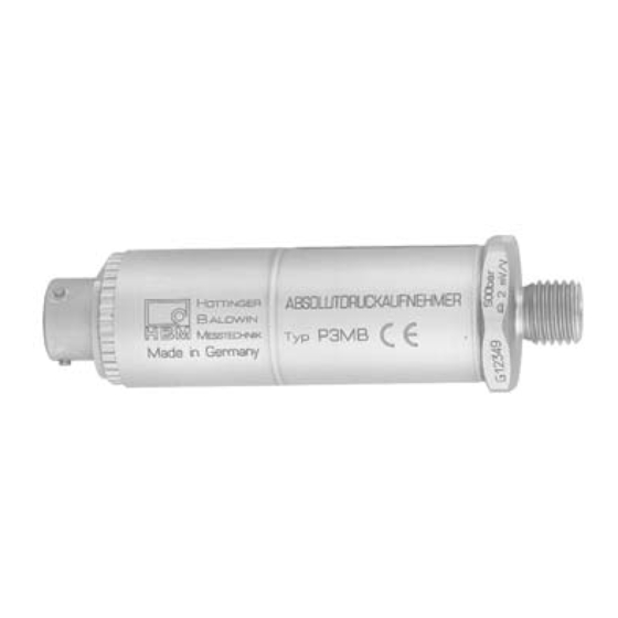
  • Seite 42: Lieferumfang

    Lieferumfang Lieferumfang S Druckaufnehmer P3 10 bis 200 bar 3‐4218.0002 U‐Seal/Usitring U12,7 x 20 x 1,5, max. 500 bar 500 bar 3‐4218.0002 U‐Seal/Usitring U12,7 x 20 x 1,5, max. 500 bar 2‐9278.0376 Beutel, Kegeldichtung P3MB/500‐3000 bar 1000 bis 3000 bar 2‐9278.0376...
  • Seite 43: Anwendung

    Daten angegebenen Stähle nicht angreifen. Der Druckauf­ nehmer wird mit seinem Gewindestutzen für den Druckanschluss befestigt und kann in beliebiger Einbaulage montiert werden. Im Einzelfall sind konkrete Hin­ weise in Kapitel 6 "Montage" zu beachten! A02239_05_YI0_02 HBM: public...
  • Seite 44: Aufbau Und Wirkungsweise

    Betriebsbedingungen die Zuverlässigkeit und Prä­ zision der Aufnehmer nicht beeinträchtigen. Die medienberührenden Teile der Aufnehmer bis 200 bar bestehen aus rostfreiem Stahl 1.4301 und 1.4542. Bei der Typenreihe P3/500 bar bis P3/ 3000bar sind sie aus rostfreiem Stahl 1.4542 gefertigt. A02239_05_YI0_02 HBM: public...
  • Seite 45: Montage

    Montage Montage GEFAHR Vor dem Ein‐ oder Ausbau des Druckaufnehmers P3 ist zu prüfen, ob die Leitung drucklos ist. Die Druckaufnehmer können in beliebiger Lage eingeschraubt werden. Wird der Aufnehmer zum Messen dynamischer Druckverläufe in Flüssigkeiten ein­ gesetzt, ist er mit dem Druckanschluss nach oben einzubauen, so dass sich im Messtubus kein Luftpolster bilden kann.
  • Seite 46 USIT-Ring Abb. 6.1 Der USIT‐Ring U 12,7x20x1,5 gehört zum mitgelieferten Zubehör der P3 Aufnehmer bis 500 bar Messbereichsendwert. Für eine einwandfreie Abdichtung müssen die Auflageflächen weitgehend plan und riefenfrei sein. Das Zapfenloch darf keine Ansenkung haben und soll nur leicht entgratet sein, da der Druck des Messmediums die Dichtlippen gegen den Aufnehmer und die Auflagefläche presst.
  • Seite 47 Doppelkegeldichtung aus rost‐ und säurebeständigem Stahl, Werkstoff‐Nr. 1.4305, mitgeliefert. Sie dichtet auch bei hohen statischen und dynamischen Drücken einwandfrei ab. a) P3/ 500 bar bis P3/ 2000 bar Anschlussbohrung und Einbau der Dichtung. b) P3/ 3000 bar Anschlussbohrung mit Entlastungsbohrung und Einbau der Dichtung.
  • Seite 48 Bei dieser Abdichtung mit Dichtscheiben nach DIN 16258 sollten nur Scheiben aus nichtmetallischen Werkstoffen eingesetzt werden. Bei Verwendung von entsprechenden metallischen Scheiben reicht das zulässige Anziehdrehmoment von 30 NVm nicht aus, um die erforderliche Flächenpressung zur einwandfreien Abdichtung zu erzielen. A02239_05_YI0_02 HBM: public...
  • Seite 49: Elektrischer Anschluss

    Anschlussbelegung P3MB und P3MBP mit Stecker HS6P P3MBP P3MB Gehäuse Gehäuse Standardausführung Option mit HS6P‐Stecker Die Zuordnung der Anschlussbelegung ist in Tab. 7.1 dargestellt. Der Kabel­ schirm ist mit dem Aufnehmergehäuse verbunden (siehe HBM‐"Green­ line‐Schirmungskonzept"; Internetdownload www.hbm.com/Greenline). Anschlussbelegung Standardausführung HS6P‐Stecker Brückenspeisespannung blau (bl) Brückenspeisespannung...
  • Seite 50 Elektrischer Anschluss Anschlussbelegung Standardausführung HS6P‐Stecker Fühlerleitung grau (gr) Gehäuse / Masse Kabelschirm Tab. 7.1 Anschlussbelegung des Druckaufnehmers P3 mit Anschlusskabel und HS6P‐Stecker Kabelbelegung P3 Top Class weiß Messsignal (+) Messsignal (-) Brückenspeisespannung (+) blau Fühlerleitung (+) grün Brückenspeisespannung (-) schwarz Fühlerleitung (-)
  • Seite 51 Elektrischer Anschluss Anschlussbelegung P3 Top Class Messsignal (+) weiß Messsignal Brückenspeise­ blau spannung (+) grün Fühlerleitung (+) Brückenspeise­ schwarz spannung (-) grau Fühlerleitung (-) Fühlerleitung orange gelb Speisespannung violett Fühlerleitung Speisespannung braun Lemo‐Buchse FFA.2E.310.CLAC65 Ansicht: Druckaufnehmer Information Hat die Messkette keine andere Verbindung mit Masse, Erde oder Netz, kann man ihr Nullpotential an die Aufnehmermasse anschließen, indem man in der...
  • Seite 52: Kabelverlängerung

    Kabelverlängerung Verlängerungskabel müssen abgeschirmt und kapazitätsarm sein. Vor allem die Speiseleitungen sollen große Querschnitte haben. HBM empfiehlt und liefert Verlängerungskabel sowie Messkabel als Meter­ ware. Bei Kabelverlängerungen ist auf einwandfreie Verbindung mit geringstem Übergangswiderstand und gute Isolation zwischen den Leitungen und Masse zu achten.
  • Seite 53: Aufnehmer-Identifikation Teds

    Aufnehmers (Elektronisches Datenblatt) aus, übersetzt diese in eigene Einstellungen und die Messung kann gestartet werden. Zum Einspeichern der Daten stellt HBM den TEDS‐Editor zur Verfügung. Dieser ist Bestandteil der Software MGCplus‐Setup‐Assistent. Der Editor ermöglicht es auch, verschiedene Benutzerrechte zu verwalten, um die grundlegenden Aufnehmerdaten gegen versehentliches Überschreiben zu...
  • Seite 54 Der letzte Bereich kann vom Anwender selbst verändert werden, z.B. mit S einem kurzen Kommentartext. S Filtereinstellungen, S Nullwert. Beispiel: Inhalt TEDS des Sensors P3 Top Class/500 bar mit der Ident‐Nr. 111310137, hergestellt im März 2007 TEDS Manufacturer Model Version letter...
  • Seite 55 Maximum Electrical Value 1.999m Mapping Method Linear Bridge type Full Impedance of each bridge element Response Time Excitation Level (Nominal) Excitation Level (Minimum) Excitation Level (Maximum) Calibration Date 4‐Mrz‐2007 Calibration Initials Calibration Period (Days) days Measurement location ID A02239_05_YI0_02 HBM: public...
  • Seite 56: Schaltung Bei Differenzdruckmessung

    Widerstand beträgt jetzt 175 Ω. zum Messverstärker Aufnehmer 1 = Differenz­ drucksignal = Brücken­ Aufnehmer 2 Klemmkasten VKK speisespannung Abb. 8.1 Schaltbild für Differenzdruckmessung Speisespannung Messspannung Aufnehmer 1 Aufnehmer 2 Als Differenzdrucksignal liegt an: U = 1/2 A02239_05_YI0_02 HBM: public...
  • Seite 57: Messen

    Drücke. Dabei ist zu beachten, dass bei Messfrequenzen im Bereich der Eigenfrequenz mit Amplitudenüberhöhungen zu rechnen ist. Bei dynamischer Beanspruchung dürfen die Druck‐Maxima nicht über dem Nenndruck liegen. Die Schwingbreite (Spitze/Spitze) der zulässigen Druck­ schwankung darf nicht größer werden als 70 % des Messbereichsendwertes. A02239_05_YI0_02 HBM: public...
  • Seite 58: Technische Daten (Nach Din 16 086)

    Technische Daten Technische Daten (nach DIN 16 086) Technische Daten P3, P3MB, P3MBP nach DIN 16086 P3, P3MB. P3MBP Mechanische Eingangsgrößen Druckart Absolutdruck Messprinzip Folien‐DMS Messbereich, 0 bar... 1000 2000 3000 Genauigkeitsklasse 0,15 0,15 Ausgangskenngrößen Nennkennwert mV/V Kennwerttoleranz 0,25 0,15 Temperatureinfluss auf das Nullsignal im Nenn­...
  • Seite 59 Technische Daten Technische Daten P3 Top Class nach DIN 16086 P3 Top Class Mechanische Eingangsgrößen Druckart Absolutdruck Messprinzip Folien‐DMS Messbereich, 0 bar... 1000 2000 3000 2500 Genauigkeitsklasse 0,15 0,15 0,13 Ausgangskenngrößen Nennkennwert mV/V 2 ±0,15% ±0,15% Kennwerttoleranz 0,15 0,10 Nullsignaltoleranz <±1...
  • Seite 60: Die Folgenden Daten Gelten Für P3 Und P3 Top Class

    Die Genauigkeitsklasse ist kein Begriff nach DIN16086. Die Zahlenangabe richtet sich nach der größten Einzelabweichung; d.h. Kennlinienabweichung (Anfangspunkteinstellung) sowie Abweichungen infolge der Temperatur bezogen auf eine Differenz von 10 K. Die folgenden Daten gelten für P3 und P3 Top Class Mechanische Eingangsgrößen Messbereich, 0 bar...
  • Seite 61 °C Referenztemperatur Nenntemperaturbereich °C -10...+80 Grenztemperaturbereich °C -40...+100 Lagertemperaturbereich °C -40...+100 Schockfestigkeit (Prüfung nach DIN 40046) Schockbeschleunigung 1000 Schockdauer Schockform Sinushalbwelle Beschleunigungsempfin <±0,001 dlichkeit pro 10 m/s2 für anregende Frequenzen von 20 % der Eigen­ frequenz A02239_05_YI0_02 HBM: public...
  • Seite 62 M12x1,5 x1,5 Elektrischer Anschluss Lemo Steckverbinder ERA.2E.310.SSL oder fest montiertes Kabel 3 m oder Gerätestecker HS6P Biegeradius des Anschlusskabels, min. statisch dynamisch Einbaulage beliebig Gewicht ohne Kabel ca. ca. 200 Schutzart (nach IP67 DIN 40050, IEC 529) A02239_05_YI0_02 HBM: public...
  • Seite 63: Abmessungen

    1 bar … 5 bar M12x 10 bar ... M12x mit Kabel­ anschluss 2000 bar 3000 bar M20x 6,5 17,5 1 bar ... 5 bar M12x mit Stecker­ 10 bar ... M12x 2000 bar anschluss 3000 bar M20x 17,5 A02239_05_YI0_02 HBM: public...
  • Seite 64 Abmessungen Zusätzlich zu beziehen: Anschlussstutzen für Messbereiche bis 500 bar; Material: Edelstahl 1.4305 Abmessungen in mm Anschlussstutzen, 1‐P3M/500/M20 M12x1,5 25 50 M20x1,5 20,2 1‐P3M/500/R1/2 M12x1,5 20 G1/2 20,2 A02239_05_YI0_02 HBM: public...
  • Seite 65: Abmessungen (In Mm) Für Die Ausführung P3 Top Class

    Abmessungen Abmessungen (in mm) für die Ausführung P3 Top Class PUR ca. Ø6 Biegeradius Anschlusskabel 1-Kab 170-3; 3 m statisch: 35 mm 1-Kab 170-7; 7 m (als Option) Biegeradius s.p.27 dynamisch: 75 mm M12 x 1,5 (M20 x 1,5 Lemo Stecker bei Mess­...
  • Seite 66: Optionen

    (nur mit Option 1 = MB) Mit Stecker HS6P, geschweißt (nur mit Option 1 = MBP) Code Option 3: Transducer Identification Ohne Transducer Identification (TEDS) Mit Transducer Identification (TEDS) (nicht mit Option 3 = K, Y, P) K-P3 A02239_05_YI0_02 HBM: public...
  • Seite 67 Mounting Instructions | Montageanleitung | Notice de montage | Istruzioni per il montaggio English Deutsch Français Italiano P3MB, P3MBP, P3 Top Class...
  • Seite 68 ..........A02239_05_YI0_02 HBM: public...
  • Seite 69: Consignes De Sécurité

    (au sens de la directive 97/23/CE concernant les équipements sous pression). Afin de garantir un fonctionnement parfait et en toute sécurité de ce capteur de pression, il convient de veiller à un transport, un stockage et un montage appropriés et d'assurer un maniement scrupuleux. A02239_05_YI0_02 HBM: public...
  • Seite 70 à surveillance. Cependant, des vérifications répétées conformément à l'article 10 de la directive européenne en matière de protection de la sécurité et de la santé des travailleurs doivent, le cas échéant, être réalisées par des personnes agréés (Pa). A02239_05_YI0_02 HBM: public...
  • Seite 71 Consignes de sécurité Recalibrage et réparation Si vous devez envoyer le capteur à HBM pour un calibrage ou une réparation, veillez à indiquer l'agent de pressurisation utilisé. Il pourrait rester des traces de cet agent dans l'orifice de mesure. Nous avons besoin de cette information afin d'être efficace et d'employer un nettoyant adapté...
  • Seite 72: Marquages Utilisés

    Conseil Ce marquage signale que des informations concernant le produit ou sa manipulation sont Information fournies. Mise en valeur Pour mettre en valeur certains mots du texte, Voir … ces derniers sont écrits en italique. A02239_05_YI0_02 HBM: public...
  • Seite 73: Marquages Utilisés Sur Le Produit

    Marquages utilisés Marquages utilisés sur le produit Label CE Avec le marquage CE, le fabricant garantit que son pro­ duit est conforme aux exigences des directives CE qui s'y appliquent (Pour voir la déclaration de conformité visitez http://www.hbm.com/HBMdoc). A02239_05_YI0_02 HBM: public...
  • Seite 74: Etendue De La Livraison

    Etendue de la livraison Etendue de la livraison S Capteur de pression P3 10 à 200 bars 3‐4218.0002 Joint en U/joint USIT U12,7 x 20 x 1,5, max. 500 bars 500 bars 3‐4218.0002 Joint en U/joint USIT U12,7 x 20 x 1,5, max. 500 bars 2‐9278.0376...
  • Seite 75: Utilisation

    Avec son manchon fileté, le capteur de pression est fixé pour le raccord de pression et peut être monté dans un sens quelconque. Parfois, il convient de tenir compte des consignes concrètes du chapitre 6 "Montage" ! A02239_05_YI0_02 HBM: public...
  • Seite 76: Conception Et Fonctionnement

    Les éléments des capteurs de 200 bars maxi. en contact avec les supports de mesure sont en acier inoxydable 1.4301 et 1.4542. Ceux de la série P3/500 bars à P3/ 3000 bars sont en acier inoxydable 1.4542. A02239_05_YI0_02 HBM: public...
  • Seite 77: Montage

    Montage Montage DANGER Préalablement au montage ou démontage du capteur de pression P3, il convient de vérifier que le câble ne soit pas sous pression. Les capteurs de pression peuvent être vissés dans une position quelconque. Lors d'une utilisation du capteur pour mesurer des pressions dynamiques dans des fluides, le raccord de pression doit être monté...
  • Seite 78 Fig. 6.1 Le joint USIT U 12,7x20x1,5 fait partie des accessoires fournis avec les capteurs P3 d'une plein échelle de 500 bars maxi. Une parfaite étanchéité nécessite une surface d'appui quasiment plane et sans stries. Le trou du tenon ne doit pas avoir de chanfrein et ne doit être que légèrement ébavuré, car la pression de l'agent de mesure presse les lèvres d'étanchéité...
  • Seite 79 Nº 1.4305 inoxydable et résistant aux acides est également fournie. Elle permet une parfaite étanchéité, même pour les pressions statiques et dynamiques. a) P3/ 500 bars à P3/ 2000 bars Alésage de raccord et montage de la garniture d'étanchéité b) P3/ 3000 bars Alésage de raccord avec alésage de décharge et montage de la garniture...
  • Seite 80 Pour cette étanchéité à l'aide de rondelles selon DIN 16258, n'utiliser que des rondelles en matériaux non métalliques. Lors de l'utilisation de rondelles métalliques, le couple de serrage admissible de 30 NVm n'est pas suffisant pour obtenir la pression superficielle nécessaire à une parfaite étanchéité. A02239_05_YI0_02 HBM: public...
  • Seite 81: Raccordement Électrique

    L'affectation du code de raccordement est présentée dans le Tab. 7.1. Le blin­ dage du câble est relié au boîtier du capteur (voir "Concept de blindage Greenline de HBM"; téléchargement dans l'Internet à l'adresse suivante : http://www.hbm.com/Greenline). Code de raccordement...
  • Seite 82 Fil de contre‐réaction gris (gr) Boîtier / masse Blindage de câble Tab. 7.1 Code de raccordement du capteur de pression P3 avec câble de liaison et connecteur HS6P Code de raccordement P3 Top Class blanc Signal de mesure (+) Signal de mesure (-)
  • Seite 83 Raccordement électrique Code de raccordement P3 Top Class blanc Signal de mesure (+) rouge Signal de mesure (-) Tension d'alim. pont (+) bleu Fil de contre réaction (+) vert noir Tension d'alim. pont (-) Fil de contre‐réaction (-) gris Fil de contre‐réaction...
  • Seite 84: Rallonge De Câble

    Les rallonges doivent être blindées et de faible capacité. Les sections des fils d'alimentation doivent notamment être importantes. HBM recommande et fournit des rallonges et des câbles de mesure au mètre. Pour les prolongations de câble, il faut veiller à une parfaite connexion à...
  • Seite 85: Identification Des Capteurs Teds

    (fiche technique électronique) et les convertit pour qu'elles conviennent à ses propres réglages ; la mesure peut démarrer. Pour enregistrer les données, HBM fournit l'éditeur TEDS. Celui‐ci fait partie intégrante du logiciel MGCplus Setup Assistent (Assistant de configuration MGCplus) L'assistant permet également de gérer des droits d'utilisateurs différents, afin...
  • Seite 86 La dernière zone peut être modifiée par l'utilisateur lui‐même, par ex. à l'aide S d'un bref commentaire, S de paramètres de filtrage, S de la valeur zéro. Exemple : Contenu TEDS du capteur P3 Top Class/500 bars ayant le nº d'identification 111310137, fabriqué en mars 2007 TEDS Manufacturer Model...
  • Seite 87 Maximum Electrical Value 1.999m Mapping Method Linear Bridge type Full Impedance of each bridge element Response Time Excitation Level (Nominal) Excitation Level (Minimum) Excitation Level (Maximum) Calibration Date 4‐Mrz‐2007 Calibration Initials Calibration Period (Days) days Measurement location ID A02239_05_YI0_02 HBM: public...
  • Seite 88: Câblage Lors D'une Mesure De Pression Différentielle

    Boîtier de raccordement VKK Fig. 8.1 Plan de connexion de mesure de pression différentielle Tension d'alimentation Tension de mesure Capteur 1 avec avec avec avec Capteur 2 On obtient le signal de pression différentielle suivant : U = 1/2 A02239_05_YI0_02 HBM: public...
  • Seite 89: Mesure

    Lors d'une sollicitation dynamique, les crêtes de pression ne doivent pas dépasser la pression nominale. L'amplitude vibratoire de la fluctuation de pression admissible ne doit pas dépasser 70 % de la pleine échelle. A02239_05_YI0_02 HBM: public...
  • Seite 90: Caractéristiques Techniques (Selon Din 16 086)

    Caractéristiques techniques Caractéristiques techniques (selon DIN 16 086) Caractéristiques techniques P3, P3MB, P3MBP selon DIN 16086 Type P3, P3MB, P3MBP Grandeurs d'entrée mécaniques Type de pression Pression absolue Principe de mesure Jauge à trame pelliculaire Etendue de mesure, bars 100 200 500 1000 2000 3000 0 bars...
  • Seite 91 Caractéristiques techniques Caractéristiques techniques P3 Top Class selon DIN 16086 Type P3 Top Class Grandeurs d'entrée mécaniques Type de pression Pression absolue Principe de mesure Jauge à trame pelliculaire Etendue de mesure, 0 bar... 1000 2000 3000 2500 Classe de précision 0,15 0,15 0,13 Caractéristiques de sortie...
  • Seite 92 écart, c.‐à‐d. écart de la courbe caractéristique (réglage du point initial) ainsi que sur les écarts dus à la température rapportés à une différence de 10 K. Les données suivantes s'appliquent aux capteurs P3 et P3 Top Class Grandeurs d'entrée mécaniques Etendue de mesure, 0 bar...
  • Seite 93 Sensibilité à l'accélération <±0,001 par 10 m/s2 pour des fréquences d'excitation de 20% de la fréquence propre Indications mécaniques Raccord de pression M12x1,5 x1,5 Raccordement électrique Connecteur Lemo ERA.2E.310.SSL ou câble fixe de 3 m ou connecteur mâle HS6P A02239_05_YI0_02 HBM: public...
  • Seite 94 Etendue de mesure, 0 bar... 1000 2000 3000 2500 Rayon de courbure du câble de liaison, min. statique dynamique Sens de montage Sans importance Poids sans câble, approx. env. 200 Degré de protection IP67 (selon DIN 40050, IEC 529) A02239_05_YI0_02 HBM: public...
  • Seite 95: Dimensions

    1 à 5 bars M12x1,5 10 bars à M12x1,5 avec câble 2000 bars attenant 3000 bars M20x1,5 17,5 1 à 5 bars M12x1,5 avec 10 bars à M12x1,5 connecteur 2000 bars 3000 bars M20x1,5 17,5 A02239_05_YI0_02 HBM: public...
  • Seite 96 A commander séparément : Raccord pour plages de mesure jusqu' à 500 bars ; matériau : acier fin 1.4305 s.p. Dimensions en mm Raccord, type s.p. 1‐P3M/500/M20 M12x1,5 25 50 M20x1,5 20,2 1‐P3M/500/R1/2 M12x1,5 20 50 G1/2 20,2 A02239_05_YI0_02 HBM: public...
  • Seite 97 Dimensions Dimensions (en mm) de la version P3 Top Class PUR ca. Ø6 Câble de liaison 1-Kab 170-3; 3 m Rayon de courbure 1-Kab 170-7; 7 m (en option) statique 35 mm Rayon de courbure s.p.27 dynamique 75 mm M12 x 1,5 (M20 x 1,5 pour l'étendue...
  • Seite 98: Options

    (uniquement avec option 1 = MB) Connecteur mâle HS6P, soudé (uniquement avec option 1 = MBP) Code Option 3: Transducer Identification Sans Transducer Identification (TEDS) Avec Transducer Identification (TEDS) (ne pas avec option 3 = K, Y, P) K-P3 A02239_05_YI0_02 HBM: public...
  • Seite 99 Mounting Instructions | Montageanleitung | Notice de montage | Istruzioni per il montaggio English Deutsch Français Italiano P3MB, P3MBP, P3 Top Class...
  • Seite 100 ..........A02239_05_YI0_02 HBM: public...
  • Seite 101: Note Sulla Sicurezza

    (ai sensi della Direttiva sulle Pressioni 97/23/CE) sopra citata. L'esercizio corretto e sicuro di questo trasduttore di pressione presuppone l'ap­ propriato trasporto, il corretto magazzinaggio e gli adeguati installazione e montaggio, nonché l'accuratezza della sua manovra. A02239_05_YI0_02 HBM: public...
  • Seite 102 Dopo aver montato lo strumento, lo si deve provare. I misuratori di pressione stessi non sono strumenti che necessitino di mon­ itoraggio, ma si consiglia comunque di far eseguire controlli ciclici da parte di A02239_05_YI0_02 HBM: public...
  • Seite 103 Ritaratura e riparazione Indicare sempre il media di pressione utilizzato quando il trasduttore viene spe­ dito alla HBM per interventi di taratura o riparazione. Nel foro di entrata pos­ sono sempre restare residui del media. Dunque, tale informazione serve per adottare il comportamento più...
  • Seite 104: Simboli Utilizzati

    Consiglio Questo simbolo segnala informazioni sul pro­ dotto o sul suo maneggio. Informazione Evidenziazione Il corsivo evidenzia il testo rimandando a capitoli, Vedere … paragrafi, figure oppure a documenti e file esterni. A02239_05_YI0_02 HBM: public...
  • Seite 105: Simboli Apposti Sull'apparecchio

    Simboli utilizzati Simboli apposti sull'apparecchio Marchio CE Con il marchio CE il costruttore garantisce che il proprio prodotto è conforme ai requisiti imposti dalle pertinenti Direttive CE (la Dichiarazione di conformità si trova nel sito http://www.hbm.com/HBMdoc). A02239_05_YI0_02 HBM: public...
  • Seite 106: Dotazione Di Fornitura

    Dotazione di fornitura Dotazione di fornitura S Trasduttore di pressione P3 10 ... 200 bar 3‐4218.0002 U‐Seal/Usitring U12,7 x 20 x 1,5, max. 500 bar 500 bar 3‐4218.0002 U‐Seal/Usitring U12,7 x 20 x 1,5, max. 500 bar 2‐9278.0376 confezione, guarnizione emisferica P3MB/500‐3000 bar 1000 ...
  • Seite 107: Applicazione

    Il trasduttore di pressione viene fissato con il pro­ prio raccordo filettato all'attacco di pressione e può essere montato in qual­ siasi posizione. In ogni singolo caso seguire le istruzioni specifiche riportate nel Cap. 6, "Montaggio". A02239_05_YI0_02 HBM: public...
  • Seite 108: Struttura E Modo Di Funzionamento

    Le parti a contatto col media dei trasduttori fino a 200 bar sono di acciaio inos­ sidabile 1.4301 ed 1.4542. I trasduttori della serie da P3/500 bar fino a P3/3000 bar sono di acciaio inossidabile 1.4542. A02239_05_YI0_02 HBM: public...
  • Seite 109: Montaggio

    L'attacco filettato M 12x1,5 od M 20x1,5 del tipo P3/3000 bar è conforme alla norma DIN 16288. Avviso Per il serraggio, usare la chiave (aperture 27) solo sulla superficie apposita­...
  • Seite 110 Fig. 6.1 Lo USIT‐Ring U 12,7x20x1,5 è compreso negli accessori in dotazione ai trasduttori P3 con campo di misura fino a 500 bar. Le superfici di appoggio devono essere lisce e prive di graffi, altrimenti la tenuta non risulterà efficace.
  • Seite 111 Nr. 1.4305. Tale guarnizione è efficace anche per elevate pressioni statiche e dinamiche. a) da P3/ 500 bar a P3/ 2000 bar Foro dell'attacco e montaggio della guarnizione. b) P3/ 3000 bar Foro dell'attacco con foro di spurgo e montaggio della guarnizione.
  • Seite 112 Per questa tenuta con rondelle di guarnizione secondo DIN 16258 si dovrebbero usare esclusivamente rondelle di materiale non metallico. Utilizzando le corrispondenti rondelle metalliche non sarà sufficiente la coppia di serraggio ammessa di 30 NVm, e non verrà raggiunta la pressione necessaria a garantire la corretta tenuta. A02239_05_YI0_02 HBM: public...
  • Seite 113: Collegamento Elettrico

    Opzione con spina HS6P L'assegnazione dei poli è riportata nella Tab. 7.1. Il cavo schermato è collegato alla custodia del trasduttore (vedere "Concetto di schermatura Greenline" della HBM; scaricabile dal sito Internet http://www.hbm.com/Greenline). Assegnazione dei poli Versione standard Spina HS6P...
  • Seite 114 Linea sensore (-) grigio (gy) Custodia / Massa Schermo del cavo (calza) Tab. 7.1 Cablaggio del trasduttore di pressione P3 con cavo di collegamento e spina HS6P Cablaggio del P3 Top Class Segnale di misura (+) bianco Segnale di misura (-)
  • Seite 115 Collegamento elettrico Cablaggio del P3 Top Class bianco Segnale di misura (+) rosso Segnale di misura (-) Tensione alimentazione ponte (+) Linea sensore (+) verde Tensione alimentazione ponte (-) nero grigio Linea sensore (-) Linea sensore arancione giallo Tensione di alimentazione...
  • Seite 116: Prolungamento Del Cavo

    I cavi di prolungamento devono essere schermati ed a bassa capacità. Partico­ larmente le linee di alimentazione devono avere grande sezione. La HBM consiglia e fornisce cavi di prolungamento e cavi di misura a metra­ ggio. Realizzando le prolunghe, fare particolare attenzione a collegamenti appro­...
  • Seite 117: Identificazione Trasduttore Teds

    (prospetto dati elettronico), li traduce in impostazioni appropriate e, a questo punto, la misurazione può iniziare immediatamente. Per memorizzare i dati la HBM mette a disposizione l'Editore TEDS. Esso è compreso nel software MGCplus Setup Assistant. L'editor consente inoltre di gestire diversi diritti utente al fine di proteggere i dati fondamentali del trasduttore dall'involontaria sovrascrittura.
  • Seite 118 S un breve commento, S le impostazioni del filtro, S il valore di zero. Esempio: Contenuto TEDS del sensore P3 Top Class/500 bar con numero d'identifica­ zione 111310137, prodotto nel Marzo 2007. TEDS Costruttore Modello Lettera della versione...
  • Seite 119 Minimum Electrical Value 1.999m Mapping Method Linear Bridge type Full Impedance of each bridge element Response Time Excitation Level (Nominal) Excitation Level (Nominal) Excitation Level (Nominal) Calibration Date 4‐Mrz‐2007 Calibration Initials Calibration Period (Days) days Measurement location ID A02239_05_YI0_02 HBM: public...
  • Seite 120: Circuito Di Misura Per Pressioni Differenziali

    Traduttore 2 scatola di giunzione VKK Fig. 8.1 Schema per la misura di pressioni differenziali Tensione di alimentazione Tensione di misura Trasduttore 1 Trasduttore 2 Il segnale di pressione differenziale presente è: U = 1/2 A02239_05_YI0_02 HBM: public...
  • Seite 121: Misurazione

    (effetto risonanza). Misurando pressioni dinamiche, non si deve mai superare la pressione nomin­ aledel trasduttore. La banda di oscillazione possibile (picco-picco) non deve mai superare il 70 % del fondo scala della pressione nominale. A02239_05_YI0_02 HBM: public...
  • Seite 122: Dati Tecnici (Secondo Din 16 086)

    Dati tecnici Dati tecnici (secondo DIN 16 086) Dati tecnici P3, P3MB, P3MBP secondo DIN 16086 Tipo P3, P3MB. P3MBP Grandezze meccaniche d'ingresso Tipo di pressione Pressione assoluta Principio di misura ER a foglio Campo di misura, 0 bar ...
  • Seite 123 Dati tecnici Dati tecnici P3 Top Class secondo DIN 16086 Tipo P3 Top Class Grandezze meccaniche d'ingresso Tipo di pressione Pressione assoluta Principio di misura ER a foglio Campo di misura, 0 bar ... 1000 2000 3000 2500 Classe di precisione...
  • Seite 124 (impostazione valore iniziale) e la deviazione dovuta alla temperatura sono relative alla differenza di 10 K. I seguenti dati valgono per P3 e P3 Top Class Grandezze meccaniche d'ingresso Campo di misura, 0 bar ...
  • Seite 125 Sensibilità all'accelerazione <±0,001 ogni 10 m/s2 per frequenze di eccitazione del 20 % della frequenza propria Dati meccanici Attacco pressione M12x1,5 x1,5 Collegamento elettrico Connettore Lemo ERA.2E.310.SSL o cavo solidale lungo 3 m o spina fissa HS6P A02239_05_YI0_02 HBM: public...
  • Seite 126 Campo di misura, 0 bar ... 2000 3000 2500 Raggio di curvatura del cavo di collegamento, min. statico dinamico Posizione di montaggio a piacere Peso senza cavo, ca. ca. 200 Grado di protezione IP67 (secondo DIN 40050, IEC 529) A02239_05_YI0_02 HBM: public...
  • Seite 127: Dimensioni

    10 bar ... 112 M12x1,5 collega­ 2000 bar mento 3000 bar 129 M20x1,5 6,5 17,5 1 bar ... 5 bar M12x1,5 con spina di 10 bar ... M12x1,5 collega­ 2000 bar mento 3000 bar 105 M20x1,5 17,5 A02239_05_YI0_02 HBM: public...
  • Seite 128 Dimensioni Da ordinare separatamente: Riduttori di connessione per campo di misura fino a 500 bar; Materiale: Acciaio inossidabile 1.4305 Dimensioni (in mm) Riduttori, tipo 1‐P3M/500/M20 M12x1,5 50 M20x1,5 20,2 1‐P3M/500/R1/2 M12x1,5 G1/2 20,2 A02239_05_YI0_02 HBM: public...
  • Seite 129 Dimensioni Dimensioni (in mm) per la versione P3 Top Class PUR ca. Ø6 Cavo di collegamentol 1-Kab 170-3; 3 m 1-Kab 170-7; 7 m (come opzione) Raggio di curvatura statico 35 mm Raggio di curvatura dinamico 75 mm AC 27...
  • Seite 130: Opzioni

    (solo con Opzione 1 = MB) con spina H6SP, saldata (solo con Opzione 1 = MBP) Cod. Opzione 3: Transducer Identification senza Transducer Identification (TEDS) con Transducer Identification (TEDS) (non con Opzione 3 = K, Y, P) K-P3 A02239_05_YI0_02 HBM: public...
  • Seite 131 Opzioni A02239_05_YI0_02 HBM: public...
  • Seite 132 HBM Test and Measurement Tel. +49 6151 803-0 Fax +49 6151 803-9100 info@hbm.com measure and predict with confidence...

Diese Anleitung auch für:

P3mbP3mbpP3 top class

Inhaltsverzeichnis