Herunterladen Inhalt Inhalt Diese Seite drucken
Inhaltsverzeichnis

Werbung

Verfügbare Sprachen
  • DE

Verfügbare Sprachen

  • DEUTSCH, seite 1
Controller MeiTronic LFC
Montage- und Bedienungsanleitung
Vor der Montage, Inbetriebnahme und Bedienung sorgfältig lesen
DE
ENG
FR
NL
CZ
POL

Werbung

Inhaltsverzeichnis
loading

Inhaltszusammenfassung für flamco meibes MeiTronic LFC

  • Seite 1 Controller MeiTronic LFC Montage- und Bedienungsanleitung Vor der Montage, Inbetriebnahme und Bedienung sorgfältig lesen...
  • Seite 2: Inhaltsverzeichnis

    Inhalt 10. Sprache Funktionsübersicht Heizkreis Mischer Sicherheitshinweise Heizungspumpe EU-Konformitätserklärung Doppelpumpe Allgemeine Hinweise Störmeldung Symbolerklärungen Dauer Ein Veränderungen am Gerät Bestimmungsgemäßer Einsatz Störungen/Wartung Gewährleistung und Haftung Entsorgung und Schadstoffe Zusatzinformationen CAN-Bus Beschreibung MeiTronic LFC Externes Relais am Signalausgang V(X) (0-10V/PWM) Technische Daten Über den Regler Tipps Lieferumfang...
  • Seite 3: Sicherheitshinweise

    Sicherheitshinweise EU-Konformitätserklärung Durch das CE-Zeichen auf dem Gerät erklärt der Hersteller, dass der MeiTronic LFC den einschlägigen Bestimmungen: EU Niederspannungsrichtlinie 2014/35/EU sowie der EU Richtlinie zur elektromagnetischen Verträglichkeit 2014/30/EU entspricht. Die Konformität wurde nachgewiesen und die entsprechenden Unterlagen sowie die EU-Konformitätserklärung sind beim Hersteller hinterlegt.
  • Seite 4: Veränderungen Am Gerät

    Veränderungen am Gerät Veränderungen, An- und Umbauten am Gerät erfordern die schriftliche Genehmigung des Herstellers. Der Einbau von Zusatzkomponenten, die nicht zusammen mit dem Gerät geprüft worden sind, ist nicht gestattet. Wenn wahrzunehmen ist, wie beispielsweise durch Beschädigung des Gehäuses, dass ein gefahrloser Gerä- tebetrieb nicht mehr möglich ist, ist das Gerät sofort außer Betrieb zu setzen.
  • Seite 5: Beschreibung Meitronic Lfc

    Beschreibung MeiTronic LFC Technische Daten Modell MeiTronic LFC Controller Temperaturreglerklasse Standbyverlust 0.5 W Anforderungsart Heizgerät Ein/Aus-Betrieb oder modulierend Elektrische Daten: Spannungsversorgung 100 - 240VAC, 50 - 60 Hz Leistungsaufnahme / Standby 0.5 - 2.5 W/ 0.5 W Schaltleistung gesamt Interne Sicherung 2 A träge 250 V Schutzart (nach DIN EN 60529) IP40...
  • Seite 6: Über Den Regler

    Über den Regler Der Controller MeiTronic LFC ermöglicht eine effiziente Nutzung und Funktionskontrolle Ihrer Pumpengruppe MeiFlow LFC MK/UK bei intuitiver Bedienbarkeit. Bei jedem Eingabeschritt sind jeder Eingabetaste passende Funktionen zugeordnet und dar- über textlich erklärt. Im Menü 'Messwerte und Einstellungen' stehen neben Schlagwörtern auch Hilfetexte und Grafiken zur Ver- fügung.
  • Seite 7: Installation

    Installation Klemmplan Kleinspannung Netzspannungen max. 24 VAC / DC 230 VAC 50 - 60 Hz Klemme: Anschluss für: Klemme: Anschluss für: GND Brücke auf den unteren Masseklemmblock Neutralleiter N Temperaturfühler 1 (Vorlauf) Netz Außenleiter L Temperaturfühler 2 (Rücklauf) 230VAC Stromversorgung für 0-10V/PWM Pumpen Temperaturfühler 3 (optional) Relais 1...
  • Seite 8: Wandmontage

    Wandmontage Controller in der Nähe der Pumpen- gruppen installieren. 1. Deckelschraube komplett lösen. 2. Klemmraumabdeckung vorsichtig vom Unterteil abziehen. Beim Abziehen wer- den auch die Klemmen ausgeklinkt. 3. Gehäuseoberteil zur Seite legen. Nicht auf die Elektronik fassen. 4. Gehäuseunterteil an der ausgewählten Position anhalten und die 3 Befes- tigungslöcher anzeichnen.
  • Seite 9: Elektrischer Anschluss

    Elektrischer Anschluss Vor Arbeiten am Gerät die Stromzuleitung abschalten und gegen Wiedereinschalten sichern! Spannungsfreiheit prü- fen! Der elektrische Anschluss darf nur durch eine Fachmann unter Berücksichtigung der geltenden Vorschriften durch- geführt werden. Das Gerät darf nicht in Betrieb genommen werden, wenn es am Gehäuse sichtbare Schäden wie z.B. Risse gibt.
  • Seite 10: Bedienung

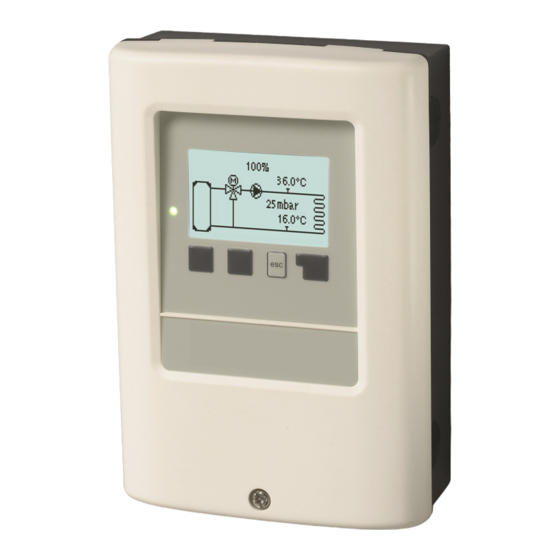
    Bedienung Anzeige und Eingabe Das Display (1) mit umfangreichem Text- und Grafikmodus ermöglicht eine einfache Bedienung des Reglers. Die Eingaben erfolgen über 4 Tasten (3+4), denen situativ unterschiedliche Funktionen zugeordnet sind. Die „esc“ Taste (3) wird genutzt, um eine Eingabe abzubrechen oder ein Menü...
  • Seite 11: Ablauf Der Inbetriebnahme

    Ablauf der Inbetriebnahme 1. Sprache und Uhrzeit einstellen 2. Inbetriebnahmehilfe a) auswählen oder b) überspringen. Die Inbetriebnahmehilfe führt in der richtigen Reihenfolge durch die not- wendigen Grundeinstellungen. Jeder Parameter wird im Reglerdisplay erklärt. Durch Drücken der "esc"-Taste gelangt man zum jeweils vor- herigen Wert zurück.
  • Seite 12: Auswertungen

    2. Auswertungen Dient zur Funktionskontrolle und Langzeitüberwachung der Anlage. Für zeitabhängige Funktionen ist es unerlässlich, dass die Uhr- zeit am Regler genau eingestellt ist. Beachten Sie, dass die Uhr bei Netzunterbrechung ca. 24 Std. weiter läuft und anschlie- ßend neu zu stellen ist. Durch Fehlbedienung oder falsche Uhr- zeit können Daten gelöscht, falsch aufgezeichnet oder überschrieben werden.
  • Seite 13: Zeiten

    3. Zeiten Einstellung von Uhrzeit, Datum und Betriebszeiten für den Heizkreis. Die zugehörigen Temperatur-Sollwerte werden im Menü 5 „Einstellungen“ festgelegt. Uhrzeit & Datum Dient zum Einstellen der aktuellen Uhrzeit und Datum. Für zeitabhängige Funktionen ist es unerlässlich, dass die Uhrzeit am Regler genau eingestellt ist. Beachten Sie, dass die Uhr bei Netzunterbrechung ca.
  • Seite 14: Betriebsart

    4. Betriebsart Manuell Es lassen sich die einzelnen Relaisausgänge und die angeschlossenen Verbraucher auf Funktion und korrekte Belegung über- prüfen. Die Betriebsart “Manuell” ist nur vom Fachmann für kurzzeitige Funktionstests z.B. bei der Inbetriebnahme zu nutzen! Funktionsweise Manuellbetrieb: Die Relais und somit die angeschlossenen Verbraucher werden mittels Tastendruck ohne Berücksichtigung der aktuellen Temperaturen und der eingestellten Parameter ein- oder ausgeschaltet.
  • Seite 15: Schutzfunktionen

    6. Schutzfunktionen In den “Schutzfunktionen” können vom Fachmann diverse Schutzfunktionen aktiviert und eingestellt werden. Die bauseitig vorzusehenden Sicherheitseinrichtungen werden keinesfalls ersetzt! Antiblockierschutz Ist der Antiblockierschutz aktiviert, schaltet der Regler die Heizungspumpe und den Mischer um 12 Uhr nacheinander für 5 Sekunden ein, um dem Festsetzen der Pumpe bzw.
  • Seite 16: Drehzahlregelung

    Signalform In diesem Menü wird die Art der Pumpe eingestellt: Heizungspumpen stellen auf größte Leistung bei kleinem Eingangssignal, Solarpumpen hingegen liefern bei kleinem Eingangssignal auch wenig Leistung. Solar = normal, Heizung = invertiert. PWM / 0-10V aus Diese Spannung / dieses Signal wird ausgegeben, wenn die Pumpe ausgeschaltet wird (Pumpen mit Kabelbruchdetektion benö- tigen eine Mindestspannung / ein Minimalsignal).
  • Seite 17: Werkseinstellungen

    vorherigen Wert, um die gewählte Einstellung nochmals anzusehen oder auch anzupassen. Mehrfaches Drücken der „esc“ Taste führt zurück zum Auswahlmodus, um die Inbetriebnahmehilfe abzubrechen Siehe " Ablauf der Inbetriebnahme " auf Seite 11 Nur vom Fachmann bei Inbetriebnahme zu starten! Beachten Sie die Erklärungen der einzelnen Parameter in dieser Anleitung, und prüfen Sie, ob für Ihre Anwendung weitere Einstellungen nötig sind.
  • Seite 18: Menüsperre

    Sensor Sendeintervall Das Sendeintervall legt fest wie oft die Sensor und Ausgangswerte des Reglers über CAN gesendet werden dürfen. Ändert sich ein Wert, wird dieser gesendet und startet das Intervall. Die nächsten Werte werden erst gesendet, wenn das Intervall abgelaufen ist.
  • Seite 19: Funktionsübersicht

    Funktionsübersicht Heizkreis Betriebsart Auto= Temperatur als SOLL-Vorlauftemperatur. Da die Betriebsart "Auto" außentemperaturgeführt regelt, muss an S4 zwingend ein Temperaturfühler angeschlossen sein. Im Automode haben die Punkte 5.1.4, 5.1.5, 5.1.6 und 5.1.14 einen Einfluss. Sollwert= Feste Vorlauftemperatur unabhängig von der Außentemperatur. Die gewünschte Vorlauftemperatur ist im Menü 5.1.3. einzugeben.
  • Seite 20: Mischer

    Max. Soll-VL Mit diesem Wert wird die Sollvorlauftemperatur des Heizkreises nach oben begrenzt. Überschreitet die Heizkreistemperatur den- noch den eingestellten Wert, wird der Heizkreis abgeschaltet bis die Temperatur wieder unter diesen Wert fällt. Nach Ablauf von 55 Sekunden wird für 5 Sekunden gespült. Bauseitig ist (z.B.
  • Seite 21: Doppelpumpe

    Up Rampe Einstellbare Laufzeit von aktueller Drehzahl der Pump bis zum Erreichen der maximalen Drehzahl. Bei einer Zapferkennung Siehe " DeltaP Soll " auf Seite 20 wird die Pumpe in dieser Zeit auf den eignestellten Maximalwert geregelt. Down Rampe Einstellbare Laufzeit, welche beim Beenden der DeltaP Runtime von dem eingestellte Drehzahlmaximalwert auf den vorherigen (Differenzdruck vor der Zapferkennung) Drehzahlwert herunter regelt.
  • Seite 22: Störmeldung

    Störmeldung Funktion ein oder ausschalten. Die Zusatzfunktion Störmeldung schaltet das Relais bei bestimmten Ereignissen ein und schaltet erst wieder ab wenn die Info- meldung zu dem jeweiligen Ereignis gelesen wurde. Dauer Ein Relais ist immer eingeschaltet. Störungen/Wartung Sicherung ersetzen Reparatur und Wartung dürfen nur durch eine Fachkraft durchgeführt werden. Vor Arbeiten am Gerät die Strom- zuleitung abschalten und gegen Wiedereinschalten sichern! Spannungsfreiheit prüfen! Verwenden Sie nur die beiliegende Reservesicherung, oder eine baugleiche Sicherung mit den folgenden Angaben: 2AT / 250 V...
  • Seite 23: Zusatzinformationen

    Zusatzinformationen CAN-Bus Über den CAN-Bus können 2 oder mehr Regler miteinander oder mit dem Datalogger verbunden werden und Daten unter- einander austauschen. 1. Die Regler werden mit dem CAN-Bus Kabel in Reihe verbunden. 2. Der erste und der letzte Regler in dieser Reihenschaltung müssen mit einem Abschlusswiderstand versehen werden.
  • Seite 24 Abschließende Erklärung Obwohl diese Anleitung mit größtmöglicher Sorgfalt erstellt worden ist, sind fehlerhafte oder unvollständige Angaben nicht aus- zuschließen. Irrtümer und technische Änderungen bleiben grundsätzlich vorbehalten. Datum und Uhrzeit der Installation: Name der Installationsfirma: Platz für Anmerkungen: Ihr Fachhändler: Hersteller: Meibes System-Technik GmbH Ringstraße 18 04827 Gerichshain - Deutschland...
  • Seite 25 Controller MeiTronic LFC Installation and operating instructions Read carefully before installation, commissioning and operation...
  • Seite 26 Content Function overview Heating Circuit Mixer Safety Instructions Heating Pump Extra Pump EU-Conformity Error message General Instructions Always On Explanation of Symbols Changes to the Unit Malfunctions/Maintenance Intended use Warranty and Liability Additional Information Disposal and Pollutants CAN bus External relay on the signal output V(X) (0-10 Description MeiTronic LFC V/PWM) Specifications...
  • Seite 27: Safety Instructions

    Safety Instructions EU-Conformity By affixing the CE mark to the unit the manufacturer declares that the MeiTronic LFC conforms to the following relevant safety reg- ulations: EU low voltage directive 2014/35/EU EU electromagnetic compatibility directive 2014/30/EU Conformity has been verified and the corresponding documentation and the EU declaration of conformity are kept on file by the manufacturer.
  • Seite 28: Changes To The Unit

    Changes to the Unit Changes, additions to or conversion of the unit are not permitted without written permission from the manufacturer. It is also not permitted to install additional components that have not been tested together with the unit. If it becomes clear that the safe operation of the unit is no longer possible, for example because of damage to the housing, turn the unit off immediately.
  • Seite 29: Description Meitronic Lfc

    Description MeiTronic LFC Specifications Model MeiTronic LFC Controller Temperature controller class Energy efficiency 4%; When operating at min. 3 ° CALEONs or RC20 a energy efficiency of 5% is achieved Standby loss 0.5 W Request type heater On/off operation or modulating Electrical specifications: Power supply 100 - 240 VAC, 50 - 60 Hz...
  • Seite 30: About The Controller

    About the Controller The controller MeiTronic LFC facilitates efficient use and function control of your Pump Group MeiFlow LFC (MC/UC) while its handling is intuitive. After every input step the suitable functions are matched to the keys and explained in a text above. In the menu 'Measurements and Settings', help text and graphics in addition to key words are available.
  • Seite 31: Installation

    Installation Electrical Terminals Low voltage Mains voltages max. 24 VAC/DC 230 VAC 50 - 60 Hz Terminal: Connection for: Terminal: Connection for: GND bridge on the lower ground terminal block Neutral N Temperature sensor 1 (flow) Mains phase L Temperature sensor 2 (return flow) 230 VAC Power Supply for 0-10 V/PWM pumps Temperature sensor 3 (optionally)
  • Seite 32: Wall Installation

    Wall Installation Install the controller near the pump groups. 1. Unscrew cover screw completely. 2. Carefully pull upper part of the housing from lower part. During the removal, the brackets are released as well. 3. Set upper part of housing aside. Do not touch the electronics.
  • Seite 33: Electrical Connection

    Electrical Connection Before working on the unit, switch off the power supply and secure it against being switched on again! Check that there is no power! Electrical connections may only be made by a specialist and must be in compliance with the applicable regulations.
  • Seite 34: Operation

    Operation Display and Input The display‘s (1), extensive text and graphical mode, enables the straightforward operation of the controller. Entries are made using 4 keys (3 + 4), to which contextual functions are assigned. The 'esc' key (3) is used to cancel an entry or to exit a menu.
  • Seite 35: Commissioning Procedure

    Commissioning procedure 1. Set language and time a) Select or b) skip the commissioning help/setup wizard. The setup wizard guides through the necessary basic settings in the cor- rect order. Each parameter is explained in the control display. Pressing the 'esc' key takes you back to the previous setting. b) With free commissioning the settings should be made in the following order: Menu 3.
  • Seite 36: Statistics

    2. Statistics This serves function control and long-term monitoring of the system. For system data statistics, it is essential for the time to be set accurately on the controller. Please note that the clock will con- tinue to run for about 24 hours, if the mains voltage is inter- rupted, and it must be reset afterwards.
  • Seite 37: Times

    3. Times Settings for time, date and operating times for the heating circuit. The associated temperature reference values are specified in Menu 5, 'Settings'. Time & Date This serve to set the current time and date. For system data statistics, it is essential for the time to be set accurately on the controller. Please note that the clock will continue to run for about 24 hours, if the mains voltage is interrupted, and it must be reset afterwards.
  • Seite 38: Operating Mode

    4. Operating mode Manual In 'Manual' mode, the individual relay outputs and the connected consumers can be checked for proper functioning and correct assignment. The operating mode 'Manual' may only be used by specialists for brief function tests, e.g. during commissioning! Functionality in manual mode: The relays and thus the connected consumers are switched on and off by pressing a key, with no regard to the current temperatures and set parameters.
  • Seite 39: Protective Functions

    6. Protective Functions 'Protective functions‘ can be used by specialists to activate and set various protective functions. The controller must never replace the safety appliances on site! Seizing Protection If the anti-seizing protection is activated, the controller will switch the heat pump and the mixer on/off for 5 seconds at 12:00 noon to prevent seizing of the pump/valve after long periods of inactivity.
  • Seite 40: Speed Control

    Output Signal In this menu, the type of pump is set: heating pumps have the highest power with a small input signal, solar pumps in contrast deliver little power with a small input signal. Solar = normal, heating = inverted. PWM/0-10 V off This signal/this voltage will be output if the pump is turned off (pumps with cable break detection require a minimum voltage/a min- imum signal).
  • Seite 41: Commissioning

    Please pay special attention to the relay’s technical information see " Specifications " on page 5. Commissioning Starting commissioning help guides you in the correct order through the basic settings necessary for commissioning, and provides brief descriptions of each parameter in the display. Pressing the 'esc' key takes you back to the previous value so you can look at the selected setting again or adjust it if desired.
  • Seite 42 Gateway Please refer to the router configuration for the gateway to be set. DNS-Server Please refer to the router configuration for the DNS server to be set. Datalogger Version Shows the software version of the datalogger. CAN bus ID Here you can see the ID of the controller on the CAN bus. Sensor send interval The send interval determines how often the sensor and output values of the controller may be sent via CAN.
  • Seite 43: Menu Lock

    8. Menu Lock This secures the controller against unintentional changes and compromising basic functions. The menus listed below remain fully accessible despite the menu lock being activated, and can be used to make adjustments if necessary: 1. Measurements 2. Statistics 3.
  • Seite 44: Function Overview

    Function overview Heating Circuit Operating mode Auto= Temperature as target flow temperature. Since the operating mode "Auto" is controlled by the outdoor temperature, it is mandatory to connect a temperature sensor at S4. In auto-mode, the points 5.1.4, 5.1.5, 5.1.6 and 5.1.14 have an influence. Reference Value = Fixed flow temperature regardless of the outdoor temperature.
  • Seite 45: Mixer

    Min. Flow The minimum flow temperature is the lower limit of the heating curve, and as such, the reference flow temperature of the heating circuit. In addition to that, the minimal flow temperature is the reference flow temperature for the frost protection function. Max.
  • Seite 46 Delta Tset The temperature difference between flow and return flow sensors. The differential temperature is determined by the rotational speed of the pump and is maintained at this value. dp fresh Entspricht der Zeit zur Ermittlung des Differenzdruckgradienten dP(vorher) - dP(aktuell). Dieser Wert ist signifikant für eine kor- rekte Zapferkennung.
  • Seite 47: Extra Pump

    Extra Pump Additional pump to relieve the heating pump. Interval Interval for pump switch over. Error message Activate or deactivate function The additional function 'error message' activates the relay for certain events and only deactivates it again when the information message for each event was read.
  • Seite 48: Malfunctions/Maintenance

    Malfunctions/Maintenance Replacing the Fuse Repairs and maintenance may only be performed by a specialist. Before working on the unit, switch off the power sup- ply and secure it against being switched on again! Check that there is no power! Only use the supplied spare fuse or a fuse of the same design with the following specifications: 2 AT/250 V If the mains voltage is switched on and the controller still does not function or dis- play anything, then the internal device fuse may be defective.
  • Seite 49: Additional Information

    Additional Information CAN bus The CAN bus can be used to connect two or more controllers with each other or with the data logger to exchange data. 1. The controllers are connected in series with the CAN bus cable. 2. The first and last controllers in this series-connection must be fitted with a terminating resist.
  • Seite 50 Final declaration Although this manual has been created with the greatest possible care, the possibility of incorrect or incomplete information cannot be excluded. This manual is subject to errors and technical changes. Date and time of installation: Name of installation company: Space for notes: Your specialist dealer: Manufacturer:...
  • Seite 51 Régulation MeiTronic LFC Instructions d'installation et de mise en route Veuillez lire attentivement cette notice avant l'installation et la mise en service !
  • Seite 52 Sommaire 10. Langue Affichage fonction Circuit de chauffage Directives de sécurité Vannes mélangeuses Déclaration de conformité UE Pompe de chauffage Recommandations générales Pompe supplémentaire Explications des symboles Messages d’erreur Modifications de l'appareil Marche continue Utilisation prévue Garantie et responsabilité Pannes et messages d’erreur Mise à...
  • Seite 53: Directives De Sécurité

    Directives de sécurité Déclaration de conformité UE En apposant le sigle CE sur laMeiTronic LFC le fabricant certifie que la construction de l'appareil est conforme aux directives de sécurité selon UE basse tension 2014/35/UE ainsi que UE Directive relative à la compatibilité électromagnétique 2014/30/UE La compatibilité...
  • Seite 54: Modifications De L'appareil

    Modifications de l'appareil Toute modification sous toute forme est soumise à l'accord préalable du fabricant. Il est également interdit d'installer des composants supplémentaires, qui n'ont pas été testés en collaboration avec l'unité. Si l'on observe qu'un fonctionnement de l'appareil n'est pas sans danger, par ex.comme suite à un endommagement, met- tez l'appareil hors service tout de suite.
  • Seite 55: Description Meitronic Lfc

    Description MeiTronic LFC Caractéristiques techniques Modèle MeiTronic LFC Controller Catégorie régulations température VI Efficacité énergétique 4%; en service avec min. 3 ° CALEONs ou RC20 un rendement énergétique de 5% est atteint Perte en attente 0,5 W Type de demande de chauffage Marche/arrêt ou modulant Valeurs électriques: Tension...
  • Seite 56: Description Du Régulateur

    Description du régulateur Le ControllerMeiTronic LFC facilite l'utilisation efficace et le contrôle des fonctions de votre Groupe de pompe MeiFlow LFC (MC / UC) tout en étant intuitif. Chaque bouton montre sur écran la commande activée avec explication en quelques mots-clé. Dans le menu "mesures et paramètres", du texte d'Aide et des graphiques en plus des mots clés sont disponibles.
  • Seite 57: Installation

    Installation Plan des bornes Basse tension Haute tension max. 24 VAC/DC 230 VAC 50 - 60 Hz Borne: Raccordement pour: Borne: Raccordement pour: Pont GND sur partie inférieure bloc terre Neutre N Sonde de température 1 (Débit) Phase principale L Sonde de température 2 (flux de retour) Alimentation 230 VAC pour Pompes 0-10 V/PWM...
  • Seite 58: Montage Mural

    Montage mural Installer le régulateur près des groupes de pompes. 1. Dévisser vis du couvercle à fond. 2. Enlever couvercle avec précaution du Faites attention que lex fixations restent avec le cou- vercle. Mettez cette partie supérieure de côtée. 3. Placer la partie supérieure du boitier. Ne pas toucher les composants électroniques.
  • Seite 59: Raccordement Électrique

    Raccordement électrique Avant de travailler sur la régulation, veiller à couper le réseau életrique et à la sécuriser contre toute remise sous ten- sion! Vérifier l'absence de toute tension! Seul un technicien formé et autorisé à effectuer le racordement électrique en respectant les préscriptions en vigueur.
  • Seite 60: Utilisation

    Utilisation Affichage et commandes Le mode texte et graphique extensible de l'affichage (1) per- met un fonctionnement simple du contrôleur. Les commandes se font en appuyant sur 4 boutons (3 + 4), chaque bouton ayant des fonctions variantes selon le pro- gramme suivi.
  • Seite 61: Procédure De Mise En Service

    Procédure de mise en service 1. Choisir la langue et régler l'horloge a) choisir ou b) sauter cette option. l'assistant aide à la mise en service/installation. a) L'aide de mise en service parcourt systématiquement les réglages de base. Expliquant chaque paramètre à...
  • Seite 62: Evaluations

    2. Evaluations Ici on contrôle les fonctions et la surveillance de l'installation. Pour l'évaluation des données il est impératif que l'heure locale est juste. En cas de coupure de courant il y a une réserve de marche de 24 h. Au delà il faudra remetrre l'horloge à l'heure. En cas de faux réglage il est possible que des données sont annulées, mal affichées ou modifées fautivement.
  • Seite 63: Heures

    3. Heures Heure, date et intervalles de fonctionnement Les températures demandées y relatives sont déter- minées dans le menu 5 "Réglages" Heure et date Sert à régler l'heure actuelle et la date. Pour l'évaluation des données il est impératif que l'heure locale est juste. En cas de coupure de courant il y a une réserve de marche de 24 h.
  • Seite 64: Mode De Fonctionnement

    4. Mode de fonctionnement Manuel Ici on contrôle les différentes sorties de relais et les composants y raccordés pour leur fonctionnement et raccordements corrects. Ce mode est à activer par un spécialiste pour des essais de fonction de courte durée, par ex. à la mise en service. Fonctionnement du mode manuel : Les relais et les composants y raccordés sont activés et désactivés e pousant les boutons sans considérer les températures actuelles et autres paramètres programmés.
  • Seite 65: Fonctions De Protection

    6. Fonctions de protection Le menu « Fonctions de protection » permet d’activer et de régler diverses fonctions de protection. Les dispositifs de sécurités à prévoir sur place ne sont en aucun cas remplacés! Protection Antiblocage Si la protection antiblocage est activée, le régulateur active le relais correspondant et l'élément raccordé tous les jours à 12 h ou le dimanche à...
  • Seite 66: Réglage De La Vitesse

    Forme de signal Dans ce menu, le type de pompe est défini: les pompes de chauffage ont la puissance la plus élevée avec un petit signal d'en- trée, les pompes solaires en revanche délivrent peu de puissance avec un petit signal d'entrée. Solaire = normal, chauffage = inversé.
  • Seite 67: Mise En Service

    R1 à R2: relais mécaniques 230V R3: possibilité de relais libre jusqu'à 230 V V1, V2: sorties PWM et 0-10 V, sortie V3: sortie 0-10 V; cf. " Relais externe sur la sortie du signal V (X) (0-10 V / PWM) " page 25 Veuillez observer les informations techniques concernant les relais (cf.
  • Seite 68 Adresse IP Vous pouvez trouver l'adresse IP à choisir dans la configuration de la passerelle. Sous-résau La configuration de votre passerelle vous indiquera le masque du sous-réseau. Gateway La configuration de votre passerelle vous indiquera le gateway DNS-Server La configuration de votre passerelle vous indiquera quel serveur choisir. Version de Datalog.
  • Seite 69: Verrouillage Des Menus

    8. Verrouillage des menus Ce menu permet de s’assurer que les valeurs paramétrées ne soient modi- fiées ou déréglées involontairement. Malgré le verrouillage des menus activé, les menus énumérés ci-après res- tent entièrement accessibles et l’on peut procéder, si nécessaire, à des modi- fication ou adaptations : 1.
  • Seite 70: Affichage Fonction

    Affichage fonction Circuit de chauffage Mode de fonctionnement Auto = Température en tant que température de flux cible. Puisque le mode de fonctionnement "Auto" est commandé par la tem- pérature extérieure, il est obligatoire de connecter une sonde de température à S4. En mode automatique, les points 5.1.4, 5.1.5, 5.1.6 et 5.1.14 ont une influence.
  • Seite 71: Vannes Mélangeuses

    Min. Débit Par la température entrée cc minimale sélectionnée, la courbe caractéristique de chauffage et ainsi la température entrée cc demandée du circuit de chauffage sont limitées vers le bas. De plus, la température minimum entrée cc est la température entrée cc demandée pour la fonction de protection antigel.
  • Seite 72 Delta Pset Réglage de la différence de pression soudaine dans le système, qui met le régulateur en mode DELTA-P et fait fonctionner la pompe à la vitesse maximale réglée pour un temps défini. Réglage de la différence de pression entre les sondes de débit et de retour.
  • Seite 73: Pompe Supplémentaire

    Pompe supplémentaire Pompe supplémentaire pour soulager la pompe de chauffage. Intervalle Intervalle de commutation de la pompe. Messages d’erreur Active ou désactive la fonction La fonction auxiliaire message d'erreur active le relais comme suite à des évènements certains et ne s'arrête qu'après que le message d'info au sujet d' l'évènement en question soit lu.
  • Seite 74: Pannes Et Messages D'erreur

    Pannes et messages d’erreur Remplacer fusibles Seul le technicien spécialisé est habilité à effectuer les réparations et entretien. Avant de travailler sur la régulation, veiller à couper le réseau életrique et à la sécuriser contre toute remise sous tension! Vérifier l'absence de toute ten- sion! Veuillez uniquement utiliser les fusibles de réserve fournis ou un fusible de type identique avec les caractéristiques suivantes : T2A / 250 V...
  • Seite 75: Informations Supplémentaires

    Informations supplémentaires CAN-Bus Par le Can-Bus on peut interconnecter 2 ou plus de régulations ou avec la passerelle Internet pour échanger mutuellement les données. 1. Les régulations sont interconnectées en utilisant les câbles CAN Bus 2. La première et denière régulation dans cette formation en série doivent être munies d'une résistance fin de bus.
  • Seite 76 Déclaration finale Bien que cette notice ait été rédigée avec le plus grand soin possible, des indications erronées ou incomplètes n’en sont pas exclues. Ce manuel est sujet à des erreurs et à des modifications techniques. Date et heure de l'installation: Nom de l'entreprise d'installation: Espace pour les notes: Votre revendeur spécialisé:...
  • Seite 77 Regelaar MeiTronic LFC Installatie- en gebruiksinstructies Lees dit zorgvuldig door voordat u de temperatuurverschilregelaar installeert, in bedrijf stelt en bedient...
  • Seite 78 Inhoudsopgave Functie-overzicht Warme Circuit Mixer Veiligheidsinstructies Verwarmingspomp Extra Pomp EU-conformiteit Foutmelding Algemene instructies Altijd aan Verklaring van symbolen Wijzigingen aan de eenheid Storingen/Onderhoud Gebruik volgens de voorschriften Garantie en aansprakelijkheid Extra informatie Verwijdering en verontreinigende stoffen CAN-bus Externe relais op signaaloutput V(X) (0-10V / PWM) 25 Beschrijving MeiTronic LFC Specificaties Tips...
  • Seite 79: Veiligheidsinstructies

    Veiligheidsinstructies EU-conformiteit De fabrikant verklaart door de CE-markering op de eenheid te plakken dat de MeiTronic LFC voldoet aan de volgende relevante veiligheidsvoorschriften: EU laagspanningsrichtlijn 2014/35/EU EU richtlijn elektromagnetische compatibiliteit2014/30/EU De conformiteit is geverifieerd en de bijbehorende documentatie en de EU conformiteitsverklaring zijn bij de fabrikant gear- chiveerd.
  • Seite 80: Wijzigingen Aan De Eenheid

    Wijzigingen aan de eenheid Wijzigingen of toevoegingen aan of conversie van de eenheid zijn niet toegestaan zonder schriftelijke toestemming van fabrikant. Het is ook verboden extra componenten te installeren die niet samen met de eenheid zijn getest. Als duidelijk wordt dat veilig bedrijf van de eenheid niet langer mogelijk is, bijvoorbeeld vanwege beschadiging van de behuizing, dient u de eenheid onmiddellijk uit te schakelen.
  • Seite 81: Beschrijving Meitronic Lfc

    Beschrijving MeiTronic LFC Specificaties Model MeiTronic LFC Controller Temperatuurcontrollerklasse Energie-efficiëntie 4%; Bij gebruik met min. 3° CALEON's of RC20 wordt een energie-efficiëntie van 5% bereikt. Standbyverlies 0.5 W Type verwarmer aanvragen On/off verrichting of modulerend Elektrische specificaties: Voeding 100 - 240 VAC, 50 - 60 Hz Vermogensverbruik/reservevermogen 0.5 - 2.5 W/ 0.5 W Totale overgeschakelde stroom...
  • Seite 82: Over De Regelaar

    Over de regelaar De Controller MeiTronic LFC maakt efficiënt gebruik en besturing van de functies van uw Pompgroep MeiFlow LFC (MC/UC) mogelijk terwijl de bediening ervan intuïtief is. Bij elke invoerstap worden de geschikte functies afgestemd met de toetsen en ver- klaard in een tekst erboven.
  • Seite 83: Installatie

    Installatie Elektrische terminals Lage spanningen Hoofdspanningen max. 24 VAC/DC 230 VAC 50 - 60 Hz Klem: Aansluiting voor: Klem: Aansluiting voor: GND-brug op het onderste grondaansluitblok Neutraal N Temperatuursensor 1 (doorstroming) Netfase L Temperatuursensor 2 (retourstroom) 230 VAC Stroomvoorziening voor 0-10 V/PWM pompen Temperatuursensor 3 (optioneel) Relais 1...
  • Seite 84: Wandmontage

    Wandmontage Installeer de regelaar in de buurt van de pompgroepen. 1. Draai de afdekkapschroef helemaal uit. 2. Verwijder het bovenste gedeelte van de behui- zing voorzichtig van het onderste gedeelte. Tij- dens het verwijderen worden de klemmen ook los gemaakt. 3.
  • Seite 85: Elektrische Aansluiting

    Elektrische aansluiting Schakel de voeding uit en borg hem tegen onbedoeld inschakelen voordat u aan de eenheid gaat werken! Controleer dat er geen spanning op staat! Elektrische aansluitingen mogen uitsluitend worden gemaakt door een specialist en in naleving van de toepasselijke regelgeving. De eenheid mag niet worden ingeschakeld als er schade aan de behui- zing zichtbaar is, bijvoorbeeld scheuren.
  • Seite 86: Bediening

    Bediening Scherm en invoer De schermen (1), uitgebreide tekst- en grafische modus maken eenvoudige, bijna voor zichzelf sprekende bediening van de regelaar mogelijk. Het invoeren wordt gedaan met 4 toetsen (3+4), waaraan contextuele functies zijn toegewezen. De toets "Esc" (3) wordt gebruikt om een invoer te annuleren of een menu te verlaten.
  • Seite 87: Inbedrijfstellingshulp

    Inbedrijfstellingshulp 1. Taal en tijd instellen a) selecteren, of b) sla over. de hulp bij inbedrijfstellings/installatiewizard. De installatiewizard leidt u in de juiste volgorde langs de noodzakelijke basisinstellingen. Elke parameter wordt uitgelegd in het bedie- ningspaneel display van de regelaar. Door op de toets "Esc" te drukken, keert u terug naar de voorgaande instelling.
  • Seite 88: Statistieken

    2. Statistieken Dient voor functiecontrole en langetermijnmonitoring van het systeem. Voor statistische gegevens over het systeem is het belangrijk dat de tijd nauwkeurig wordt ingesteld op de regelaar. Bij onder- breking van de voeding blijft de klok nog ongeveer 24 uur lopen.
  • Seite 89: Tijden

    3. Tijden Instellingen voor tijd, datum en bedrijfstijden van het CV-circuit. De bijbehorende temperatuurreferentiewaarden zijn gespecificeerd in menu 5, 'Instellingen'. Datum en tijd Dient voor het instellen van huidige datum en tijd Voor statistische gegevens over het systeem is het belangrijk dat de tijd nauwkeurig wordt ingesteld op de regelaar. Bij onderbreking van de voeding blijft de klok nog ongeveer 24 uur lopen.
  • Seite 90: Bedrijfsmodus

    4. Bedrijfsmodus Handmatig In de "Handmatige" modus kunnen de individuele relaisuitgangen en de aangesloten verbruikers worden gecontroleerd op juiste werking en correcte toewijzing. De bedrijfsmodus "Handmatig" mag uitsluitend worden gebruikt door specialisten voor korte functietesten, bij- voorbeeld tijdens de inbedrijfstelling! Werking in handmatige modus: de relais en dus de aangesloten gebruikers worden in- en uitgeschakeld door een toets in te drukken, onafhankelijk van de actuele temperaturen en ingestelde parameters.
  • Seite 91: Beschermingsfuncties

    6. Beschermingsfuncties De 'Beschermingsfuncties‘ kunnen worden gebruikt door specialisten om verschillende beschermingsfuncties te activeren en in te stellen. De thermostaat mag de veiligheidsvoorzieningen nooit ter plaatse vervangen! Antiblokkeerbeveiliging Als de antiblokkeerbeveiliging is geactiveerd, schakelt de regelaar de warmtepomp en de mixer 5 seconden in/uit om 12:00 uur 's middags om vastlopen van de pomp/klep na lange inactieve periodes te voorkomen.
  • Seite 92: Snelheidsregeling

    Uitgangssignaal In dit menu wordt het pomptype ingesteld: verwarmingspompen hebben de grootste uitvoer met een klein inangssignaal. Solar = normaal, verwarming = omgekeerd. PWM / 0-10V uit Dit signaal / dit voltage wordt uitgezonden als de pomp uitgeschakeld is (pompen met kabelbreukdetectie vereisen een minimaal voltage / een minimum signaal).
  • Seite 93: Inbedrijfstelling

    R1 naar R2: mechanisch relais 230V R3: potentiaalvrij relais tot 230 V mogelijk. V1, V2: PWM- en 0-10 V-uitgangen, V3: 0-10 V-uitgang; zie " Externe relais op signaaloutput V(X) (0-10V / PWM) " op pagina 25 Let op de technische informatie van het relais zie " Specificaties " op pagina 5. Inbedrijfstelling Opstarten met de opstartassistent leidt u in de juiste volgorde door de voor de inbedrijfstelling noodzakelijke basisinstellingen, waarbij de betreffende parameters op het scherm kort verklaard worden.
  • Seite 94 IP-adres Zie de routerconfiguratie voor het IP-adres dat moet worden ingesteld. Subnet Zie de routerconfiguratie voor het subnet dat moet worden ingesteld. Gateway Zie de routerconfiguratie voor de gateway die moet worden ingesteld. DNS-server Zie de routerconfiguratie voor de DNS-server die moet worden ingesteld. DataLogger versie Toont de softwareversie van de datalogger.
  • Seite 95: Menuvergrendeling

    8. Menuvergrendeling Borg de regelaar tegen onbedoeld veranderen en in gevaar brengen van basisfuncties. De onderstaande menu's blijven volledig toegankelijk, ook als de menu- vergrendeling is ingeschakeld, en kunnen worden gebruikt om eventuele noodzakelijke afstellingen te doen: 1. Meetwaarden 2. Statistieken 3.
  • Seite 96: Functie-Overzicht

    Functie-overzicht Warme Circuit Bedrijfsmodus Auto= Temperatuur als gewenste aanvoertemperatuur. Aangezien de bedrijfsmodus "Auto" wordt geregeld door de bui- tentemperatuur, is het verplicht om een temperatuursensor op S4 aan te sluiten. In de automatische modus hebben de punten 5.1.4, 5.1.5, 5.1.6 en 5.1.14 invloed. Referentiewaarde = Vaste aanvoertemperatuur ongeacht de buitentemperatuur.
  • Seite 97: Mixer

    Min. Flow De minimumvoorlooptemperatuur is de ondergrens van de verwarmingscurve en dus de referentie voorlooptemperatuur van het verwarmingscircuit. Bovendien is de minimale vertrektemperatuur de referentie-aanvoertemperatuur voor de vorst- beschermingsfunctie. Max. Flow Deze waarde is de bovengrens van de referentie-aanvoertemperatuur van het CV-circuit. Als de temperatuur van het CV-circuit echter de ingestelde waarde overschrijdt, schakelt het CV-circuit uit tot de temperatuur onder deze waarde daalt.
  • Seite 98 Delta Pset Instelling van het plotselinge drukverschil in het systeem, waardoor de regelaar in de DELTA-P-modus wordt gezet en de pomp op het voor een bepaalde tijd ingestelde maximumtoerental draait. Stel het drukverschil tussen debiet- en retoursensoren in. Delta Tset Het temperatuurverschil tussen de aanvoer- en retoursensoren.
  • Seite 99: Extra Pomp

    Extra Pomp Zie Relaisfuncties" op pagina 1. Interval Interval voor het omschakelen van de pomp. Foutmelding Activeer of deactiveer functie De extrafunctie foutmeldingen activeert het relais voor bepaalde gebeurtenissen en deactiveert het pas weer als het infor- matiebericht over elke gebeurtenis is te lezen. Altijd aan Relais is permanent ingeschakeld.
  • Seite 100: Storingen/Onderhoud

    Storingen/Onderhoud De zekering vervangen Reparaties en onderhoud mogen uitsluitend door een specialist worden uitgevoerd. Schakel de voeding uit en borg hem tegen onbedoeld inschakelen voordat u aan de eenheid gaat werken! Controleer dat er geen spanning op staat! Gebruik uitsluitend de meegeleverde reservezekering of een zekering van hetzelfde ontwerp met de volgende spe- cificaties: 2 AT/250 V Als de hoofdspanning is ingeschakeld en de computer nog steeds niet werkt of niets weergeeft op het scherm, kan de interne apparaatzekering defect zijn.
  • Seite 101: Extra Informatie

    Extra informatie CAN-bus De CAN-bus kan worden gebruikt om twee of meer regelaars met elkaar of et de datalogger te verbinding om gegevens uit te wis- selen. 1. De regelaars worden serieel aangesloten met de CAN-buskabel. 2. De eerste en de laatste regelaar in deze seriële aansluiting moeten zijn voorzien van een afsluit- weerstand.
  • Seite 102 Eindverklaring Hoewel veel zorg is besteed aan het opstellen van deze instructies, kan de mogelijkheid dat bepaalde informatie onjuist of incom- pleet is niet worden uitgesloten. Deze handleiding is onderhevig aan fouten en technische wijzigingen. Installatiedatum en -tijdstip Naam van installerend bedrijf: Ruimte voor aantekeningen: Uw gespecialiseerde dealer: Fabrikant:...
  • Seite 103 Regulátor MeiTronic LFC Návod k montáži a obsluze Přečtěte si jej pozorně před instalací, uvedením do provozu a samotným provozem...
  • Seite 104 Obsah Přehled funkcí Otopný okruh Směšovač Bezpečnostní pokyny Topné čerpadlo Čerpadlo navíc EU-Soulad Chybová zpráva Obecné pokyny Vždy zapnuto Vysvětlení symbolů Změny na jednotce Poruchy/Údržba Určené využití Záruka a odpovědnost Další funkcí Likvidace a polutanty Sběrnice CAN Externí relé na signálním výstupu V(X) (0-10V / PWM)25 Popis MeiTronic LFC Specifikace Rady...
  • Seite 105: Bezpečnostní Pokyny

    Bezpečnostní pokyny EU-Soulad Připojením označení CE k zařízení výrobce prohlašuje, že splňuje MeiTronic LFC následující příslušné bezpečnostní předpisy: EU směrnice pro nízké napětí 2014/35/EU EU směrnice elektromagnetické kompatibility 2014/30/EU Soulad byl prokázán a odpovídající dokumentace a EU prohlášení o souladu jsou uloženy u výrobce. Obecné...
  • Seite 106: Změny Na Jednotce

    Změny na jednotce Změny, dodatky nebo konverze jednotky nejsou povoleny bez písemného povolení od výrobce. Stejně tak je zakázáno instalovat další komponenty, které nebyly testovány spolu s jednotkou. Pokud je zřejmé, že bezpečný provoz jednotky již není možný, například kvůli škodám na plášti, přístroj vypněte okamžitě. Všechny díly přístroje nebo příslušenství, které...
  • Seite 107: Popis Meitronic Lfc

    Popis MeiTronic LFC Specifikace Model MeiTronic LFC Regulátor Třída regulátoru teploty Energetická účinnost 4% ; Při provozu na min. 3 ° CALEONs nebo RC20 je dosaženo energetické účinnosti 5% Ztráta v pracovním režimu 0.5 W Požadovat typ ohřívače Zapnutí/vypnutí provozu nebo modulace Elektrické...
  • Seite 108: O Regulátoru

    O regulátoru regulátor MeiTronic LFC zajišťuje efektivní použití a ovládání funkcí vašeho Skupina čerpadel MeiFlow LFC (MC/UC) při jeho intuitivním řízení. Po každém vstupním kroku jsou vhodné funkce přiřazeny ke klíčům a vysvětleny v textu výše. V nabídce „měření hodnot a nastavení“ jsou kromě klíčových slov i pomocné texty a obrázky. MeiTronic LFC může být využito pro různé...
  • Seite 109: Instalace

    Instalace Elektrické koncovky Nízké napětí Síťové napětí max. 24 VAC/DC 230 V střídavý proud 50 - 60 Hz Koncovka: Připojení pro: Koncovka: Připojení pro: GND most na dolní svorkovnici Neutrál N Teplotní senzor 1 (průtok) Síťová fáze L Teplotní senzor 2 (zpětný tok) 230 VAC napájení...
  • Seite 110: Instalace Na Stěnu

    Instalace na stěnu Nainstalujte ovladač poblíž skupin čerpadel. 1. Úplně odšroubujte šroub na krytu. 2. Opatrně vytáhněte horní část pláště od spodní části. Během odstraňování jsou uvolněny i podpěry. 3. Horní část krytu odložte stranou. Nedotýkejte se elektroniky. 4. Držte spodní část krytu ve zvolené pozici a označte tři montážní...
  • Seite 111: Elektrické Připojení

    Elektrické připojení Než začnete pracovat na dané jednotce, vypněte napájení a zajistěte jej proti opětovnému zapnutí! Zkontrolujte, že neproudí žádný proud! Elektrické připojení může být provedeno pouze odborníkem v souladu s platnými předpisy. Jednotka nesmí být uvedena do provozu, pokud pozorujeme viditelné poškození na jejím plášti - např. trhliny. Jednotka nemusí...
  • Seite 112: Provoz

    Provoz Displej a vstup Displej (1), rozsáhlý textový a grafický režim, který umožňuje jednoduché, téměř intuitivní, ovládání regulátoru. Zápisy jsou prováděny pomocí 4 tlačítek (3+4, jimž jsou přiřazeny kontextové funkce. Tlačítko „esc“ (3) se používá ke zrušení zadání nebo k opuštění menu. V některých případech může být požadováno potvrzení, zda provedené...
  • Seite 113: Pomoc S Uvedením Do Provozu

    Pomoc s uvedením do provozu 1. Nastavení jazyka a času a) vybrat nebo b) přeskočit pomoc s uvedením do provozu / průvodce nastavením. Instalační průvodce vás provede nezbytnými základními nastaveními ve správném pořadí. Každý parametr je vysvětlen na ovládacím displeji. Stisknutím „esc“ se vrátíte do předchozího nastavení. b) V případě...
  • Seite 114: Statistiky

    2. Statistiky Slouží pro ovládání funkcí a dlouhodobé monitorování systému. Pro statistiky systémových dat je nezbytné nastavit na regulátoru přesný čas. Vezměte prosím na vědomí, že při přerušení napětí hodiny nadále běží po dobu asi 24 hodin. Poté musejí být přenastaveny. Nesprávný provoz nebo nepřesný čas mohou mít za následek vymazání...
  • Seite 115: Časové Programy

    3. Časové programy Nastavení času, data a provozní doby topného obvodu. Související referenční hodnoty teploty jsou specifikovány v Menu 5, „Nastavení“. Hodina a datum Slouží k nastavení aktuálního času a data. Pro statistiky systémových dat je nezbytné nastavit na regulátoru přesný čas. Vezměte prosím na vědomí, že při přerušení...
  • Seite 116: Provozní Režim

    4. Provozní režim Manuální V režimu „Manuální“ mohou být zkontrolovány jednotlivé výstupy relé a připojené spotřebiče pro správné fungování a přiřazení. Provozní režim „Manuální“ smí být používán pouze odborníky pro krátké funkční testy, např. během uvádění do provozu! Funkce v manuálním režimu: relé a tím i připojené spotřebiče jsou zapínány a vypínány stiskem tlačítka bez ohledu na aktuální...
  • Seite 117: Ochranné Funkce

    6. Ochranné funkce „Ochranné funkce“ mohou být použity odborníky k aktivaci a nastavení různých ochranných funkcí. Ovladač nesmí nikdy vyměnit bezpečnostní zařízení na místě! Ochrana proti zablokování Pokud je aktivována ochrana proti zatuhnutí, regulátor spouští/vypíná tepelné čerpadlo a směšovač v poledne na dobu pěti sekund jako prevenci proti zatuhnutí...
  • Seite 118: Řízení Rychlosti

    Výstupní signál V tomto menu se nastavuje typ čerpadla: tepelná čerpadla mají největší výstup s malým vstupním signálem, solární čerpadla mají velmi naopak velmi malý výstupní a malý vstupní signál. Solární = normální, vytápění = obrácený. PWM / 0-10V vypnuto Tento signál / toto napětí...
  • Seite 119: Uvedení Do Provozu

    Uvedení do provozu Průvodce počátečním uvedením do provozu vás provede správným postupem při základním nastavování pro uvedení do provozu a poskytne krátký popis každého z parametrů na displeji. Stisknutím klávesy „esc“ se vrátíte k předchozí hodnotě, abyste se mohli znovu podívat na zvolené nastavení a v případě potřeby jej upravit. Opakovaným stisknutím klávesy „esc“ se vrátíte do režimu výběru, čímž...
  • Seite 120 DNS server Pro nastavení DNS serveru, prosím, vizte konfiguraci routeru. Verze Datalogger Zobrazí softwarovou verzi dataloggeru. ID sběrnice CAN Zde můžete vidět ID regulátoru na sběrnici CAN. Interval odesílání senzoru Interval odesílání určuje, jak často mohou být hodnoty na senzoru a výstupní hodnoty odesílány pomocí CAN. Pokud se hodnota změní, je odeslána a interval začíná.
  • Seite 121: Zámek Menu

    8. Zámek menu Zabezpečte regulátor proti neúmyslným změnám a ohrožení základních funkcí. Menu uvedená níže zůstávají kompletně přístupná i přes aktivovaný zámek menu a mohou být použita pro nutné úpravy. 1. Měřené hodnoty 2. Statistika 3. Časové programy 8. Zámek menu 9.
  • Seite 122: Přehled Funkcí

    Přehled funkcí Otopný okruh Provozní režim Auto= teplota jako cílová teplota průtoku. Protože provozní režim „Auto“ je řízen podle venkovní teploty, je nutné připojit teplotní senzor v S4. V automatickém režimu mají vliv body 5.1.4, 5.1.5, 5.1.6 a 5.1.14. Referenční hodnota = stálá teplota průtoku bez ohledu na venkovní teplotu. Požadovaná teplota průtoku S1 musí být nastavena v Menu 5.1.3.
  • Seite 123: Směšovač

    Max. Průtok Tato hodnota je horní mez referenční teploty průtoku topného obvodu. Pokud však teplota topného obvodu překročí nastavenou hodnotu, topný obvod se vypne, dokud teplota neklesne pod tuto hodnotu. Po 55 sekundách oplachujte po dobu 5 sekund. Zákazník musí zajistit další limitující termostat, který je pro bezpečnost připojen k čerpadlům v sérii (např. podlahové vytápění).
  • Seite 124 dp čerstvé Odpovídá době pro stanovení diferenciálního tlakového gradientu dP(dříve) - dP(nyní). Tato hodnota je významná pro správné rozpoznání stáčení. Doba proplachu Po tuto dobu čerpadlo běží při plné rychlosti (100%), aby bylo zaručeno bezpečné nastartování. Teprve po uplynutí této doby budou otáčky čerpadla ovládány a přepínány v závislosti na nastavení...
  • Seite 125: Čerpadlo Navíc

    Čerpadlo navíc Přídavné čerpadlo pro ulehčení topnému čerpadlu. Interval Interval pro přepnutí čerpadla. Chybová zpráva Aktivovat nebo deaktivovat funkci Dodatečná funkce „chybová zpráva“ aktivuje relé pro určité události a znovu jej deaktivuje pouze při čtení informační zprávy pro každou událost. Vždy zapnuto Relé...
  • Seite 126: Poruchy/Údržba

    Poruchy/Údržba Výměna pojistky Opravy a údržbu může provádět pouze specialista. Než začnete pracovat na dané jednotce, vypněte napájení a zajistěte jej proti opětovnému zapnutí! Zkontrolujte, že neproudí žádný proud! Použijte pouze dodanou náhradní pojistku nebo pojistku stejné konstrukce s následujícími specifikacemi: 2 AT/250 V Pokud je síťové...
  • Seite 127: Další Funkcí

    Další funkcí Sběrnice CAN Sběrnice CAN může být použita pro propojení dvou nebo více ovladačů s data loggerem pro výměnu dat. 1. Ovladače jsou připojeny v sérii kabelem sběrnice CAN. 2. První a poslední ovladače v tomto sériovém zapojení musejí být vybaveny koncovým odporem.
  • Seite 128 Závěrečné prohlášení I když tyto instrukce byly vytvořeny s co možná největší pečlivostí, možnost nesprávných nebo neúplných informací nemůže být vyloučena. Tato příručka podléhá chybám a technickým změnám. Datum a čas instalace: Jméno montážní firmy: Prostor pro poznámky: Váš odborný prodejce: Výrobce: Meibes System-Technik GmbH Ringstraße 18...
  • Seite 129 Kontroler MeiTronic LFC Instrukcja instalacji i obsługi Przeczytaj uważnie przed instalacją, uruchomieniem i korzystaniem z urządzenia.
  • Seite 130 Zawartość Przegląd funkcji Obieg grzewczy Napęd Zasady bezpieczeństwa Pompa Grzewcza Dodatkowa Pompa UE-deklaracja zgodności Wiadomość błędu Wskazówki ogólne Zawsze wł. Wyjaśnienie symboli Zmiany w urządzeniu Usterki/Konserwacja Użytkowanie zgodne z przeznaczeniem Gwarancja i odpowiedzialność Dodatkowe Informacje Usuwanie odpadów i materiałów szkodliwych Magistrala CAN Zewnętrzny przekaźnik na wyjściu sygnału V(X) (0- OpisMeiTronic LFC...
  • Seite 131: Zasady Bezpieczeństwa

    Zasady bezpieczeństwa UE-deklaracja zgodności Producent poprzez oznakowanie znakiem zgodności z CE MeiTronic LFC oświadcza, że odpowiada określonym przepisom bezpieczeństwa: UEdyrektywa niskonapięciowa2014/35/UE UE dyrektywa elektromagnetycznej kompatybilności2014/30/UE Zgodność została zweryfikowana. Odpowiednia dokumentacja i UE deklaracja zgodności są przechowywane w archiwum producenta. Wskazówki ogólne Prosimy o uważne przeczytanie! Niniejsza instrukcja montażu i obsługi zawiera podstawowe informacje oraz wskazówki dotyczące bezpieczeństwa, instalacji, rozruchu, konserwacji i optymalnego korzystania z urządzenia.
  • Seite 132: Zmiany W Urządzeniu

    Zmiany w urządzeniu Zmiany, uzupełnienia lub konwersje urządzenia są zabronione bez pisemnej zgody producenta. Nie można również instalować dodatkowych podzespołów, które nie zostały przetestowane z urządzeniem. Jeśli bezpieczna praca urządzenia nie jest możliwa, np. z powodu uszkodzenia obudowy, należy natychmiast wyłączyć urządzenie.
  • Seite 133: Opismeitronic Lfc

    OpisMeiTronic LFC Dane techniczne Model MeiTronic LFC Kontroler Klasa kontrolera temperatury Energooszczędność 4%; przy pracy w min. Przy 3° CALEONs lub RC20 uzyskuje się sprawność energetyczną 5%. Straty w trybie czuwania 0,5 W Żądanie typu nagrzewnicy Wł./wył. lub regulacja Parametry elektryczne: Napięcie zasilania 100 - 240VAC, 50 - 60 Hz Zużycie energii / gotowość...
  • Seite 134: Informacje O Kontrolerze

    Informacje o kontrolerze kontrolerMeiTronic LFCułatwia efektywne użytkowanie i kontrolę funkcji Grupa pomp MeiFlow LFC (MC/UC), podczas gdy sama obsługa jest intuicyjna. Przy każdym wprowadzaniu odpowiednie funkcje są dopasowywane do klawiszy i objaśniane w instrukcji powyżej. W menu "Pomiary i Ustawienia" dostępny jest tekst objaśniający, grafika oraz słowa kluczowe. MeiTronic LFC może być...
  • Seite 135: Instalacja

    Instalacja Zaciski elektryczne Niskie napięcie Napięcie sieci  maks. 24 VAC/DC 230 VAC 50-60 Hz Zacisk: Przyłącze dla: Zacisk: Przyłącze dla: Most GND na dolnym bloku zacisków uziemienia Neutralny N Czujnik temperatury 1 (przepływ) Faza główna L Czujnik temperatury 1 (przepływ zwrotny) Zasilanie 230 VAC dla Pompy 0-10V/PWM Czujnik temperatury 3 (opcjonalny)
  • Seite 136: Montaż Ścienny

    Montaż ścienny Zamontuj kontroler w pobliżu zespołu pomp. 1. Odkręć całkowicie śrubę pokrywy. 2. Ostrożnie pociągnąć górną część obudowy od części dolnej. W trakcie zdejmowania zwalnianie są również klamry. 3. Odłóż górną część obudowy na bok. Nie dotykaj elektroniki. 4. Przytrzymaj dolną część obudowy do wybranej pozycji i zaznacz trzy otwory montażowe.
  • Seite 137: Połączenie Elektryczne

    Połączenie elektryczne Przed pracami przy wymianie bezpiecznika należy odłączyć zasilanie i zabezpieczyć przed ponownym włączeniem! Sprawdzić brak napięcia! Połączenia elektryczne mogą być wykonywane wyłącznie przez specjalistę i zgodnie z obowiązującymi przepisami. Urządzenie nie może zostać uruchomione, jeżeli widoczne są uszkodzenia obudowy, np. spękania.
  • Seite 138: Obsługa

    Obsługa Wyświetlacz i wprowadzanie danych Tryby wyświetlania (1), rozległy tekst i tryb graficzny, umożliwiają proste, prawie intuicyjne sterowanie pracą kontrolera. Wprowadzanie ustawień następuje poprzez 4 przyciski (3+4), które zależnie od sytuacji przyporządkowane są różnym funkcjom. Przycisk "esc" (3) jest używany, aby przerwać...
  • Seite 139: Procedura Uruchamiania

    Procedura uruchamiania 1. Ustawienia języka i godziny a) wybierz lub b) pomiń. pomoc w rozruchu technologicznym / kreator ustawień. Kreator ustawień przeprowadzi Ciebie przez niezbędne ustawienia podstawowe we właściwej kolejności. Każdy parametr jest wyjaśniony w sterowniku wyświetlacz. Naciśnięcie klawisza "esc" powoduje powrót do poprzedniego ustawienia.
  • Seite 140: Statystyki

    2. Statystyki Służy do sterowania funkcjami i długoterminowego monitorowania systemu. W przypadku statystyk danych systemowych istotne jest dokładne ustawienie czasu na kontrolerze. Jeśli napięcie sieciowe zostanie przerwane, należy pamiętać, iż zegar będzie pracował przez ok. 24 godziny, po czym musi zostać zresetowany.
  • Seite 141: Okresy

    3. Okresy Ustawienia czasu, daty i czasu pracy obiegu grzewczego. Wartości referencyjne temperatury są określone w menu 5, 'Ustawienia'. Data i czas Służy do ustawienia aktualnej godziny i daty. W przypadku statystyk danych systemowych istotne jest dokładne ustawienie czasu na kontrolerze. Jeśli napięcie sieciowe zostanie przerwane, należy pamiętać, iż...
  • Seite 142: Tryb Operacyjny

    4. Tryb operacyjny Ręczny W trybie "ręcznym" poszczególne wyjścia przekaźnikowe i podłączone odbiorniki mogą być testowane pod kątem funkcjonowania i prawidłowego przyporządkowania. Tryb pracy "Ręczny" może być wykorzystywany wyłącznie przez specjalistów do krótkich testów funkcji, np. podczas uruchamiania! Funkcja w trybie ręcznym: Przekaźniki, a tym samym podłączone odbiorniki są włączane i wyłączane przez naciśnięcie klawisza, bez względu na bieżące temperatury i ustawione parametry.
  • Seite 143: Zabezpieczenia

    6. Zabezpieczenia "Funkcje ochronne" mogą być wykorzystywane przez specjalistów do aktywacji i instalacji różnych funkcji ochronnych. Kontroler pod żadnym pozorem nie może wymieniać urządzeń zabezpieczających na terenie obiektu! Antyblokada Jeśli antyblokada jest włączona, kontroler włącza/wyłącza mikser na 5 sekund o godz. 12:00 w południe, aby zapobiec zablokowaniu pompy po długim okresie bezczynności.
  • Seite 144: Kontr. Obrotów

    Sygnał Wyj. W tym menu ustawiany jest typ pompy: pompy ciepła mają najwyższą moc przy małym sygnale wejściowym, natomiast pompy solarne dostarczają niewielką moc przy małym sygnale wejściowym. Solar = normalny, ogrzewanie = odwrócone. PWM/0-10 V wył. Sygnał/napięcie będzie wysyłane, jeśli pompa zostanie wyłączona (pompy, u których wykryto przerwanie kabla wymagają minimalnego napięcia/sygnału).
  • Seite 145: Rozruch Technologicz

    R3: możliwy przekaźnik bezpotencjałowy do 230 V V1, V2: Wyjścia PWM i 0-10 V, V3: wyjście 0-10 V; patrz " Zewnętrzny przekaźnik na wyjściu sygnału V(X) (0-10V/PWM) " na stronie25 Proszę zwrócić szczególną uwagę na informacje techniczne przekaźnika; patrz " Dane techniczne " na stronie5. Rozruch technologicz.
  • Seite 146 Adres IP Proszę zapoznać się z konfiguracją routera w celu ustalenia adresu IP, który ma zostać przydzielony. Maska podsieci W celu ustawienia maski podsieci proszę zapoznać się z konfiguracją routera maski podsieci. Brama dostępu Proszę zapoznać się z konfiguracją routera dla bramy dostępu, która ma zostać ustawiona. Proszę...
  • Seite 147: Zabezpieczenie Menu

    8. Zabezpieczenie menu Zabezpiecza sterownik przed niezamierzonymi zmianami i naruszeniem podstawowych funkcji. Wymienione poniżej menu pozostają w pełni dostępne pomimo włączonej blokady menu i w razie potrzeby mogą być wykorzystywane do dokonywania zmian w ustawieniach: 1. Pomiary 2. Statystyki 3. Okresy 8.
  • Seite 148: Przegląd Funkcji

    Przegląd funkcji Obieg grzewczy Tryb operacyjny Auto= Temperatura jako docelowa temperatura przepływu. Ponieważ tryb pracy "Auto" jest kontrolowany przez temperaturę zewnętrzną, konieczne jest podłączenie czujnika temperatury w S4. W trybie automatycznym funkcjonują punkty 5.1.4, 5.1.5, 5.1.6 i 5.1.14. Wartość odniesienia = stała temperatura zasilania niezależnie od temperatury zewnętrznej. Żądaną temperaturę zasilania S1 ustawia się...
  • Seite 149: Napęd

    Min. zasilanie Minimalna temperatura zasilania jest jednocześnie dolną granicą krzywej grzewczej oraz referencyjną temperaturą zasilania obiegu grzewczego. Ponadto minimalna temperatura zasilania jest temperaturą referencyjną zasilania dla funkcji zapobiegającej zamarzaniu. Max. zasilanie Wartość ta jest górną granicą referencyjnej temperatury zasilania obiegu grzewczego. Jeśli jednak temperatura obiegu grzewczego przekroczy ustawioną...
  • Seite 150 Delta Pset Regulacja nagłej różnicy ciśnień w systemie, która przełącza sterownik w tryb DELTA-P i uruchamia pompę z maksymalną prędkością obrotową na określony czas. Ustawia różnicę ciśnień pomiędzy czujnikami przepływu i powrotu. Delta Tset Różnica temperatur pomiędzy czujnikami przepływu i powrotu. Różnica temperatur zależy od prędkości obrotowej pompy i jest utrzymywana na tej samej wartości.
  • Seite 151: Dodatkowa Pompa

    Dodatkowa Pompa Dodatkowa pompa do wspomagania pompy grzewczej. Interwał Interwał przełączania pompy. Wiadomość błędu Aktywuj lub dezaktywuj funkcję Dodatkowa funkcja "komunikat o błędzie" aktywuje przekaźnik dla określonych zdarzeń i dezaktywuje go dopiero po odczytaniu komunikatu każdego ze zdarzeń. Zawsze wł. Przekaźnik jest stale włączony.
  • Seite 152: Usterki/Konserwacja

    Usterki/Konserwacja Wymiana bezpiecznika Naprawa i konserwacja może być przeprowadzana tylko przez osobę posiadającą odpowiednie uprawnienia. Przed pracami przy wymianie bezpiecznika należy odłączyć zasilanie i zabezpieczyć przed ponownym włączeniem! Sprawdzić brak napięcia! Należy używać tylko załączonych bezpieczników rezerwowych, lub bezpiecznika o tej samej budowie z następującymi danymi technicznymi: 2 AT/250V W przypadku gdy napięcie sieciowe jest włączone, a sterownik nie odpowiada lub nie wyświetla żadnych informacji, wewnętrzny bezpiecznik urządzenia może być...
  • Seite 153: Dodatkowe Informacje

    Dodatkowe Informacje Magistrala CAN Magistrala CAN może być wykorzystywana do połączenia dwóch lub więcej kontrolerów bądź z rejestratorem danych w celu ich wymiany. 1. Sterowniki są równolegle połączone z kablem magistrali CAN. 2. Pierwszy i ostatni sterownik w tej serii - połączenie musi być wyposażony w rezystor terminacyjny.
  • Seite 154 Deklaracja Końcowa Mimo, iż niniejsza instrukcja została opracowana z największą możliwą starannością, możliwość wystąpienia nieprawidłowych lub niekompletnych informacji nie jest wykluczona. Niniejsza instrukcja może zawierać błędne informacje lub zmiany techniczne. Data i czas instalacji: Nazwa firmy wykonawczej: Uwagi: Autoryzowany przedstawiciel: Producent: Meibes System-Technik GmbH Ringstraße 18...

Inhaltsverzeichnis