Inhaltsverzeichnis
Werbung
Verfügbare Sprachen
Verfügbare Sprachen
Quicklinks
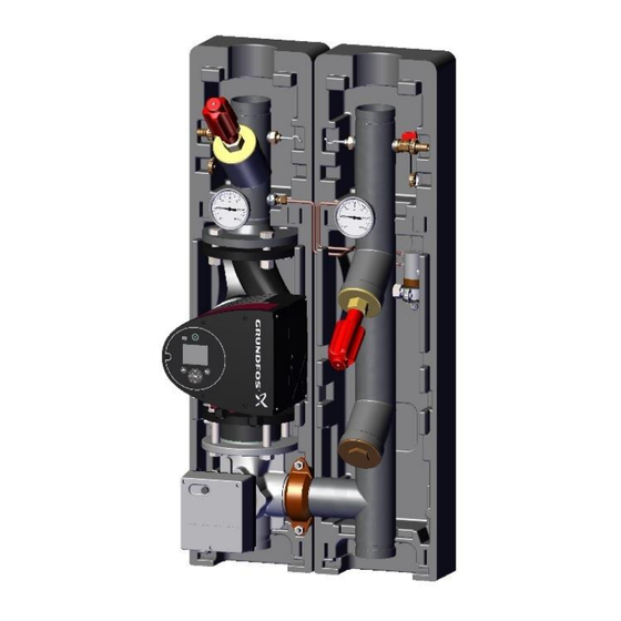
MeiFlow M LFC
Pumpengruppen für / Pump groups for
MeiTronic LFC Regelung / controller
und optionales Zubehör / and optional accessories
DEU
Montage-/ Service-Anleitung
GB
Installation / Service Instructions
FR
Instructions de montage et de service
NL
Montage-/ servicehandleiding
CZ
Montážní a servisní návod
POL
Instrukcja montażu i serwisu
IT
Istruzioni per il montaggio e la manutenzione
ESP
Instrucciones de montaje/servicio
POR
Instruções de montagem/assistência
RUS
Руководство по монтажу/сервисному обслуживанию
Meibes System-Technik GmbH
Ringstrasse 18
D-04827 Gerichshain, Germany
Seite
2
Page
15
Page
28
Pagina
41
Strana
54
Strona
67
Pagina
80
Página
93
Página
106
Стр.
119
Tel.: +49(0) 3 42 92 7 13-0
Fax: +49(0) 3 42 92 7 13-808
info@meibes.com
E-Mail:
www.flamcogroup.com
Werbung
Kapitel
Inhaltsverzeichnis

Verwandte Anleitungen für flamco meibes Logotherm MeiFlow M LFC


Inhaltszusammenfassung für flamco meibes Logotherm MeiFlow M LFC
- Seite 1 MeiFlow M LFC Pumpengruppen für / Pump groups for MeiTronic LFC Regelung / controller und optionales Zubehör / and optional accessories Montage-/ Service-Anleitung Seite Installation / Service Instructions Page Instructions de montage et de service Page Montage-/ servicehandleiding Pagina Montážní a servisní návod Strana Instrukcja montażu i serwisu Strona...
-
Seite 2: Inhaltsverzeichnis
Inhalt Sicherheitshinweise ......................... 3 Vorschriften/Richtlinien ......................3 Bestimmungsgemäße Verwendung ..................4 Erstinbetriebnahme ......................... 4 Arbeiten an der Anlage ......................4 Haftung ............................ 4 Geräte und Funktionsbeschreibung ....................5 Funktionsbeschreibung ......................5 Temperaturdifferenzabhängige Pumpenleistungsberechnung ..........5 Aufbau der Pumpengruppen ......................6 Schematische Darstellung ....................... -
Seite 3: Sicherheitshinweise
1. Sicherheitshinweise Lesen Sie vor der Montage diese Anleitung sorgfältig durch. Die Montage und Erstinbetriebnahme der Baugruppe darf nur von einer zugelassenen Fachfirma ausgeführt werden. Machen Sie sich vor Arbeitsbeginn mit allen Teilen und deren Handhabung vertraut. Die Anwendungsbeispiele innerhalb dieser Bedienungsanleitung sind Ideenskizzen. -
Seite 4: Bestimmungsgemäße Verwendung
Bestimmungsgemäße Verwendung Verwendung in Heizungsanlagen nach DIN EN 12828. Unsachgemäße Montage sowie zweckentfremdetes Betreiben Baugruppe schließt alle Gewährleistungsansprüche aus. Alle Absperrarmaturen dürfen nur vom zugelassenen Fachmann im Servicefall geschlossen werden, da ansonsten die Sicherheitsarmaturen ihre Wirkung verlieren. Vorsicht: Nehmen Sie keine Veränderungen an den elektrischen Bauteilen, der Konstruktion oder den hydraulischen Komponenten vor! Sie beeinträchtigen sonst die sichere Funktion der Anlage. -
Seite 5: Geräte Und Funktionsbeschreibung
2. Geräte und Funktionsbeschreibung Jede Produktgruppe (PGs, Regelung, weiteres Zubehör) ist einzeln verfügbar und einzeln bestellbar! Funktionsbeschreibung Die Pumpengruppe mit dem Heizkreisregler dient der Versorgung eines Heiznetzes mit Heizwasser. Als Ausgangsgrößen werden Druck- und Temperaturdifferenzen in der Regelung ausgewertet. Hierbei wird der Volumenstrom geregelt. -
Seite 6: Aufbau Der Pumpengruppen
3. Aufbau der Pumpengruppen Schematische Darstellung V-PG, DN 32 FL-PG, DN40 / 50 / 65 LFCH für ungemischten Kreis (UC) LFCH-M für gemischten Kreis (MC) Legende: S1) VL- Fühler S2) RL-Fühler S4) AT-Fühler S5) Dp-Fühler PG MeiFlow M LFC -DEU- Seite 6 Stand: Okt-20... -
Seite 7: Abmessungen Und Komponenten V-Pg, Dn 32
Abmessungen und Komponenten V-PG, DN 32 LFCH für ungemischten Kreis (UC) LFCH-M für gemischten Kreis (MC) Legende: B) Kugelhahn mit Thermometer D) HE-Pumpe G) Absperrkugelhahn J) Mischer mit Stellmotor K) Kugelhahn mit Thermometer und integrierten Rückflussverhinderer S1) VL- Fühler S2) RL-Fühler S5) Dp-Fühler PG MeiFlow M LFC -DEU- Seite 7... -
Seite 8: Abmessungen Und Komponenten Fl-Pg, Dn 40, 50 Und 65
Abmessungen und Komponenten FL-PG, DN 40, 50 und 65 LFCH für ungemischten Kreis (UK) LFCH-M für gemischten Kreis (MC) Legende: A) Schrägsitzventil und RV B) Thermometer C) Schmutzfänger oder mögl. Strangregulierventil D) HE-Pumpe F) KFE-Hahn G) Absperrventil H) Entlüfter J) Mischer mit Stellmotor S1) VL-Fühler S2) RL-Fühler S5) Dp-Fühler... -
Seite 9: Optionales Zubehör
4. Optionales Zubehör Wandhalterungen für Pumpengruppen DN 32 - 65 DN 32 für V-PG (UC/MC) inkl. 2 ÜWM, flachdichtend DN 40 / 50 / 65 für FL-PG (UC/MC) inkl. 2 BigFixlock- Schellen Hinweis: weiteres Zubehör, wie Übergänge, Absperrsets, Zählereinbaustrecken siehe Preisliste PG MeiFlow M LFC -DEU- Seite 9 Stand: Okt-20... -
Seite 10: Meitronic Lfc - Elektrische Verschaltung Und Verkabelungspläne
MeiTronic LFC - Elektrische Verschaltung und Verkabelungspläne Heizkreis-Pumpe, MeiTronic LFC Typ GF Magna 3 Regelung Stellmotor für MC Sensor Außentemp. -fühler Es wird die elektrische Hinweis: Verdrahtung des Reglers mit Bitte die separate Anleitung flexiblen Kabeln und zur MeiTronic LFC Regelung Aderendhülsen empfohlen. -
Seite 11: Klemmplan: Allgemeine Darstellung
4.2.1 Klemmplan: Allgemeine Darstellung PG MeiFlow M LFC -DEU- Seite 11 Stand: Okt-20... -
Seite 12: Klemmplan Für Ungemischte Pumpengruppen
4.2.2 Klemmplan für Ungemischte Pumpengruppen PG MeiFlow M LFC -DEU- Seite 12 Stand: Okt-20... -
Seite 13: Klemmplan Für Gemischte Pumpengruppen, Stellmotor Mit 230 V
4.2.3 Klemmplan für gemischte Pumpengruppen, Stellmotor mit 230 V PG MeiFlow M LFC -DEU- Seite 13 Stand: Okt-20... -
Seite 14: Klemmplan Für Gemischte Pumpengruppen, Stellmotor Mit 24 V
4.2.4 Klemmplan für gemischte Pumpengruppen, Stellmotor mit 24 V PG MeiFlow M LFC -DEU- Seite 14 Stand: Okt-20... - Seite 15 Contents Safety instructions ......................... 16 Regulations/guidelines ......................16 Intended use .......................... 17 Commissioning ........................17 When working on the system....................17 Liability ..........................17 Devices and functional description ....................18 Functional description ......................18 Differential temperature dependent calculation of pump output ........18 Set-up of the pump groups ......................
-
Seite 16: Safety Instructions
1. Safety instructions Read these instructions carefully before installing. The installation and initial start-up of the assembly may only be performed by an approved specialist company. Please familiarise yourself with all the parts and their handling before starting work. The application examples in these operating instructions are basic sketches only. Local laws and guidelines must be taken into account. -
Seite 17: Intended Use
Intended use For use in heating systems in accordance with DIN EN 12828. Installing and operating the assembly incorrectly will invalidate any warranty claims. The shut-off valves may only be closed by an approved specialist when servicing, otherwise the safety valves will not work. Caution: Do not make any changes to the electrical components, the design of the system or the hydraulic components! This would adversely impact on the safe function of the system. -
Seite 18: Devices And Functional Description
2. Devices and functional description Each product group (PGs, controller, other accessories) is available and can be ordered separately! Functional description The pump group with the heating circuit controller is used to supply a heating network with heating water. Pressure and temperature differentials are analysed as output variables in the control system. In this way, the volume flow is controlled. -
Seite 19: Set-Up Of The Pump Groups
3. Set-up of the pump groups Visual representation V-PG, DN 32 FL-PG, DN40 / 50 / 65 LFCH Heat Heat for the consumer consumer unmixed circuit (UC) Heat generator Heat generator LFCH-M Heat Heat for the mixed consumer consumer circuit (MC) Heat Heat generator generator... -
Seite 20: Dimensions And Components V-Pg, Dn 32
Dimensions and components V-PG, DN 32 LFCH approx. LFCH for the DN32 unmixed circuit (UC) approx. 373 LFCH-M LFCH-M approx. DN32 for the mixed circuit (MC) approx. 373 Legend: B) Kugelhahn mit Thermometer D) HE-Pumpe G) Absperrkugelhahn J) Mischer mit Stellmotor K) Kugelhahn mit Thermometer und integrierten Rückflussverhinderer S1) VL sensor S2) RL sensor... -
Seite 21: Dimensions And Components Fl-Pg, Dn 40, 50 And 65
Dimensions and components FL-PG, DN 40, 50 and 65 LFCH LFCH approx. e.g.: DN65: for the BigFixlocknut unmixed circuit (UC) BigFixlocknut approx. 495 LFCH-M LFCH-M approx. 420 e.g.: DN65: for the mixed BigFixlocknut circuit (MC) BigFixlocknut approx. 495 Legend: A) Angle seat valve and RV B) Thermometer C) Dirt trap or possible circuit control valve D) HE pump... -
Seite 22: Optional Accessories
4. Optional accessories Wall brackets for pump groups DN 32 - 65 DN 32 for V-PG (UC/MC) including 2 ÜWM, Flat sealing DN32 (V-PG) DN 40 / 50 / BigFixlock-nut for FL-PG (UC/MC) including 2 -BigFixlock -BigFixlock BigFixLock clamps DN 40 - 65 (FL-PG) Note: for additional accessories, such as junctions, shut-off sets, meter installation pipe lengths, see price list... -
Seite 23: Meitronic Lfc - Electrical Switching And Cabling Plans
MeiTronic LFC - electrical switching and cabling plans Heating circuit pump MeiTronic LFC Type GF Magna 3 controller Servomotor for MC sensor Outside temp. sensor We recommend using flexible Note: Please follow the cables with wire end ferrules for the controller wiring. separate instructions on the MeiTronic LFC For service/ maintenance... -
Seite 24: Block Plan: General Representation
4.2.1 Block plan: General representation PG MeiFlow M LFC -ENG- Page 24 Last updated: Oct-20... -
Seite 25: Block Plan For Unmixed Pump Groups
4.2.2 Block plan for unmixed pump groups PG MeiFlow M LFC -ENG- Page 25 Last updated: Oct-20... -
Seite 26: Block Plan For Mixed Pump Groups, Servomotor At 230 V
4.2.3 Block plan for mixed pump groups, servomotor at 230 V PG MeiFlow M LFC -ENG- Page 26 Last updated: Oct-20... -
Seite 27: Block Plan For Mixed Pump Groups, Servomotor At 24 V
4.2.4 Block plan for mixed pump groups, servomotor at 24 V PG MeiFlow M LFC -ENG- Page 27 Last updated: Oct-20... - Seite 28 Sommaire Consignes de sécurité ........................29 Réglementations/directives ....................29 Utilisation conforme ......................30 Première mise en service ...................... 30 Interventions sur l'installation ....................30 Responsabilité ........................30 Appareils et description du fonctionnement ................31 Description du fonctionnement .................... 31 Calcul de la puissance de pompage en fonction de la différence de température ....31 Montage des groupes de pompe ....................
-
Seite 29: Consignes De Sécurité
1. Consignes de sécurité Avant le montage, veuillez lire attentivement la présente documentation. Seule une société spécialisée et agréée est autorisée à effectuer le montage et la première mise en service du groupe. Avant de commencer le travail, familiarisez-vous bien avec les pièces et leur fonctionnement. Les exemples d'application contenus dans le présent manuel d'instructions sont des illustrations. -
Seite 30: Utilisation Conforme
Utilisation conforme Utilisation dans des installations de chauffage suivant DIN EN 12828. Un montage incorrect et une exploitation non conforme du groupe annulent les droits de garantie. Tous les robinets d'arrêt doivent être fermés uniquement par le personnel autorisé en cas d'intervention, faute de quoi les robinets de sécurité... -
Seite 31: Appareils Et Description Du Fonctionnement
2. Appareils et description du fonctionnement Chaque groupe de produits (PGs, réglage, autres accessoires) est disponible de manière séparée et il est possible de commander les pièces individuelles ! Description du fonctionnement Le groupe de pompe équipé du régulateur pour circuit de chauffage sert à alimenter un réseau de chauffage en eau chaude. -
Seite 32: Montage Des Groupes De Pompe
3. Montage des groupes de pompe Représentation schématique V-PG, DN 32 FL-PG, DN40 / 50 / 65 LFCH Consommate pour circuit de Consommateur ur de chaleur de chaleur chauffage non-mélangé (UK) générateur de générateur de chaleur chaleur Consommateur LFCH-M de chaleur pour circuit de Consommateur de chaleur... -
Seite 33: Mesures Et Composants V-Pg, Dn 32
Mesures et composants V-PG, DN 32 LFCH env.260 LFCH pour circuit de DN32 chauffage non-mélangé (UK) env.373 LFCH-M env.260 LFCH-M DN32: pour circuit de chauffage mélangé (MK) env.373 PG MeiFlow M LFC -FR- Page 33 Version : oct.-20... -
Seite 34: Mesures Et Composants Fl-Pg, Dn 40, 50 Et 65
Mesures et composants FL-PG, DN 40, 50 et 65 LFCH LFCH env.420 p.ex. : DN65 : pour circuit de BigFixlocknut chauffage non-mélangé (UK) BigFixlocknut env.495 LFCH-M LFCH-M env.420 p.ex. : DN65 : pour circuit de BigFixlocknut chauffage mélangé (MK) BigFixlocknut env.495 Légende : A) Robinet de vanne à... -
Seite 35: Accessoires En Option
4. Accessoires en option Supports muraux pour groupes de pompe DN 32 - 65 DN 32 pour V-PG (UK/MK) avec 2 ÜWM, À joints plats DN32 (V-PG) DN40 / 50 / Écrou BigFixlock pour FL-PG (UK/MK) avec 2 colliers BigFixlock- BigFixlock- écrou écrou... -
Seite 36: Meitronic Lfc - Câblage Électrique Et Plans De Câblage
MeiTronic LFC - câblage électrique et plans de câblage Pompe du circuit de Réglage chauffage. MeiTronic LFC Type GF Magna 3 Servomote ur pour MK Capteur Sonde de temp. ext. Il est recommandé d’effectuer le raccordement électrique du régulateur avec des Remarque : câbles flexibles et des Veuillez lire les... -
Seite 37: Schéma Des Bornes : Représentation Générale
4.2.1 Schéma des bornes : Représentation générale PG MeiFlow M LFC -FR- Page 37 Version : oct.-20... -
Seite 38: Schéma Des Bornes Pour Groupes De Pompe Non-Mélangés
4.2.2 Schéma des bornes pour groupes de pompe non-mélangés PG MeiFlow M LFC -FR- Page 38 Version : oct.-20... -
Seite 39: Schéma Des Bornes Pour Groupes De Pompe Mélangés, Servomoteurs Avec Du 230 V
4.2.3 Schéma des bornes pour groupes de pompe mélangés, servomoteurs avec du 230 V PG MeiFlow M LFC -FR- Page 39 Version : oct.-20... -
Seite 40: Schéma Des Bornes Pour Groupes De Pompe Mélangés, Servomoteurs Avec Du
4.2.4 Schéma des bornes pour groupes de pompe mélangés, servomoteurs avec du 24 V PG MeiFlow M LFC -FR- Page 40 Version : oct.-20... - Seite 41 Inhoud Veiligheidsaanwijzingen ........................ 42 Voorschriften/richtlijnen ....................... 42 Doelmatig gebruik ......................... 43 Eerste inbedrijfname ......................43 Werken aan de installatie ...................... 43 Aansprakelijkheid ........................43 Apparaten en functiebeschrijving ....................44 Functiebeschrijving ........................ 44 Berekening van de pompcapaciteit afhankelijk van het temperatuurverschil ..... 44 Opbouw van de pompgroepen .....................
-
Seite 42: Veiligheidsaanwijzingen
1. Veiligheidsaanwijzingen Lees voor de montage deze handleiding aandachtig door. De montage en de eerste inbedrijfstelling van de module mogen uitsluitend worden uitgevoerd door een erkend vakbedrijf. Zorg er voor aanvang van de werkzaamheden voor dat u bekend bent met alle onderdelen en het gebruik ervan. De toepassingsvoorbeelden in deze gebruikshandleiding zijn ideeschetsen. De lokale wetgeving en richtlijnen dienen steeds in acht te worden genomen. -
Seite 43: Doelmatig Gebruik
Doelmatig gebruik Toepassing in verwarmingsinstallaties conform CEN DIN EN 12828. Door onreglementaire montage en ondoelmatig gebruik van de module vervalt elke mogelijke aanspraak op garantie. Alle afsluitarmaturen mogen uitsluitend door erkend vakpersoneel worden gesloten voor onderhoud, aangezien de veiligheidsarmaturen anders hun functie verliezen. Pas op: Voer geen veranderingen aan de elektrische componenten, de constructie of de hydraulische componenten uit! Dit kan ertoe leiden dat de installatie niet meer veilig functioneert. -
Seite 44: Apparaten En Functiebeschrijving
2. Apparaten en functiebeschrijving Iedere productgroep (pompgroepen, regeling, additioneel toebehoren) is apart beschikbaar en te bestellen! Functiebeschrijving De pompgroep met verwarmingscircuitregelaar verzorgt de toevoer van verwarmingswater naar een verwarmingscircuit. In deze regelaar worden druk- en temperatuurverschillen geanalyseerd als uitgangswaarden. Hierdoor wordt het debiet geregeld. Als uitgangswaarde voor de pompaansturing wordt steeds de hoogste van beide pompcapaciteiten genomen, die volgen uit de parallelle berekeningen van de druk- en temperatuurverschillen. -
Seite 45: Opbouw Van De Pompgroepen
3. Opbouw van de pompgroepen Schematische weergave V-PG, DN 32 FL-PG, DN40/50/65 LFCH Warmte- voor Warmte- verbruiker verbruiker ongemengd circuit (UK) Warmte- Warmte- bron bron Warmte- LFCH-M verbruiker voor gemengd Warmte- verbruiker circuit (MK) Warmte- bron Warmte- bron Legenda: S1) VL-sensor S2) RL-sensor S4) AT-sensor S5) Dp-sensor... -
Seite 46: Afmetingen En Componenten V-Pg, Dn 32
Afmetingen en componenten V-PG, DN 32 LFCH ca. 260 LFCH voor DN32 ongemengd circuit (UK) ca. 373 LFCH-M ca. 260 LFCH-M DN32: voor gemengd circuit (MK) ca. 373 PG MeiFlow M LFC -NL- Pagina 46 Editie: okt-20... -
Seite 47: Afmetingen En Componenten Fl-Pg, Dn 40, 50 En 65
Afmetingen en componenten FL-PG, DN 40, 50 en 65 LFCH LFCH ca. 420 bv.: DN65: voor BigFixlocknut ongemengd circuit (UK) BigFixlocknut ca. 495 LFCH-M LFCH-M ca. 420 bv.: DN65: voor gemengd BigFixlocknut circuit (MK) BigFixlocknut ca. 495 Legenda: A) Afsluiter en terugslagklep B) Thermometer C) Vuilvanger of mogelijk inregelklep D) HR-pomp... -
Seite 48: Optionele Accessoires
4. Optionele accessoires Muurbeugels voor pompgroepen DN 32 - 65 DN 32 voor V-PG (UK/MK) incl. 2 ÜWM, vlakdichtend DN32 (V-PG) DN40/50/65 BigFixlock-nut voor FL-PG (UK/MK) incl. 2 BigFixLock- BigFixlock- BigFixlock- klemmen DN 40 - 65 (FL-PG) Opmerking: voor ander toebehoren zoals koppelingen, afsluitsets, inbouwmodules voor meters: zie prijslijst PG MeiFlow M LFC -NL- Pagina 48... -
Seite 49: Meitronic Lfc - Elektrische Bedradings- En Bekabelingsplannen
MeiTronic LFC - Elektrische bedradings- en bekabelingsplannen Verwarmingscircuitpo MeiTronic LFC-regeling Type GF Magna 3 Stelmotor voor MK sensor Buitentemp. -sensor De elektrische bedrading van de regelaar met flexibele kabels en adereindhulzen wordt Opmerking: aanbevolen. Neem alstublieft ook de aparte handleiding van Voor service-/ de MeiTronic Regeling onderhoudswerkzaamhede... -
Seite 50: Klemplan: Algemene Weergave
4.2.1 Klemplan: Algemene weergave PG MeiFlow M LFC -NL- Pagina 50 Editie: okt-20... -
Seite 51: Klemplan Voor Ongemengde Pompgroepen
4.2.2 Klemplan voor ongemengde pompgroepen PG MeiFlow M LFC -NL- Pagina 51 Editie: okt-20... -
Seite 52: Klemplan Voor Gemengde Pompgroepen, Stelmotor Met 230 V
4.2.3 Klemplan voor gemengde pompgroepen, stelmotor met 230 V PG MeiFlow M LFC -NL- Pagina 52 Editie: okt-20... -
Seite 53: Klemplan Voor Gemengde Pompgroepen, Stelmotor Met 24 V
4.2.4 Klemplan voor gemengde pompgroepen, stelmotor met 24 V PG MeiFlow M LFC -NL- Pagina 53 Editie: okt-20... - Seite 54 Obsah Bezpečnostní upozornění ......................55 Předpisy/směrnice ......................... 55 Používání ke stanovenému účelu ..................56 První uvedení zařízení do provozu ..................56 Práce na zařízení ........................56 Ručení ............................ 56 Zařízení a popis funkce ........................57 Popis funkce .......................... 57 Výpočet výkonu čerpadla v závislosti na rozdílu teplot ............57 Konstrukce čerpadlových skupin ....................
-
Seite 55: Bezpečnostní Upozornění
1. Bezpečnostní upozornění Před montáží si pečlivě přečtěte tento návod. Montáž a první uvedení konstrukčního celku do provozu smí provádět výhradně odborná firma. Před zahájením prací se podrobně seznamte se všemi díly a jejich používáním. Příklady použití v tomto návodu jsou pouze ilustrační nákresy. Vždy musí být zohledněny místní zákony a směrnice. -
Seite 56: Používání Ke Stanovenému Účelu
Používání ke stanovenému účelu Používání v topných zařízeních podle normy EN 12828. Neodborná montáž a používání konstrukčního celku za provozu v rozporu se stanoveným účelem vylučují veškeré nároky ze záruky. Všechny uzavírací armatury smí uzavřít pouze autorizovaný kvalifikovaný odborník při provádění... -
Seite 57: Zařízení A Popis Funkce
2. Zařízení a popis funkce Každá skupina výrobků (čerpadlová skupina, regulační systém, další příslušenství) je k dispozici samostatně a je možné ji samostatně objednat! Popis funkce Čerpadlová skupina s regulátorem topného okruhu slouží k zásobování topné sítě horkou vodou. Jako výstupní... -
Seite 58: Konstrukce Čerpadlových Skupin
3. Konstrukce čerpadlových skupin Schematické zobrazení V-PG, DN 32 FL-PG, DN40 / 50 / 65 LFCH Tepelný Tepelný spotřebič spotřebič nesměšovaný okruh (UK) Zdroj tepla Zdroj tepla Tepelný LFCH-M spotřebič Tepelný spotřebič směšovaný okruh (MK) Zdroj tepla Zdroj tepla Legenda: S1) Čidlo přívodu S2) Čidlo zpátečky S4) Čidlo venkovní... -
Seite 59: Rozměry A Komponenty V-Pg, Dn 32
Rozměry a komponenty V-PG, DN 32 LFCH cca 260 LFCH DN32 nesmíěšovaný okruh (UK) cca 373 LFCH-M cca 260 LFCH-M DN32: směšovaný okruh (MK) cca 373 PG MeiFlow M LFC -CZ- Strana 59 Poslední aktualizace: říj-20... -
Seite 60: Rozměry A Komponenty Fl-Pg, Dn 40, 50 A 65
Rozměry a komponenty FL-PG, DN 40, 50 a 65 LFCH LFCH cca 420 např.: DN65: Matice BigFixlock nesměšovaný okruh (UK) BigFixlocknut cca 495 LFCH-M LFCH-M cca 420 např.: DN65: BigFixlocknut směšovaný okruh (MK) BigFixlocknut cca 495 Legenda: A) Ventil se šikmým vřetenem a zpětnou klapkou B) Teploměr C) Sítko;... -
Seite 61: Volitelné Příslušenství
4. Volitelné příslušenství Konzole na stěnu pro čerpadlové skupiny DN 32 pro V-PG (nesměšovaný/směšovaný topný okruh) včetně. 2 přesuvných ějš ějš matic, plošně těsnicí DN32 (V-PG) DN40 / 50 / 65 Matice BigFixlock pro FL-PG (nesměšovaný/směšovaný topný okruh) vč. 2 spon pro BigFixlock BigFixlock- BigFixlock- matice... -
Seite 62: Meitronic Lfc - Elektrické Zapojení A Schémata Kabelových Rozvodů
MeiTronic LFC - Elektrické zapojení a schémata kabelových rozvodů Čerpadlo topného Regulace okruhu, MeiTronic LFC Typ GF Magna 3 Čidlo Servomotor diferen čního směšovaný tlaku topný okruh Čidlo venkovní teploty Regulátor doporučujeme Upozornění: připojit do elektrické sítě Současně dodržujte pomocí flexibilních kabelů samostatný... -
Seite 63: Schéma Svorek: Obecné Zobrazení
4.2.1 Schéma svorek: Obecné zobrazení PG MeiFlow M LFC -CZ- Strana 63 Poslední aktualizace: říj-20... -
Seite 64: Schéma Zapojení Pro Čerpadlové Skupiny Bez Směšování
4.2.2 Schéma zapojení pro čerpadlové skupiny bez směšování PG MeiFlow M LFC -CZ- Strana 64 Poslední aktualizace: říj-20... -
Seite 65: Schéma Zapojení Pro Čerpadlové Skupiny Se Směšováním, Servomotor S 230 V
4.2.3 Schéma zapojení pro čerpadlové skupiny se směšováním, servomotor s 230 V PG MeiFlow M LFC -CZ- Strana 65 Poslední aktualizace: říj-20... -
Seite 66: Schéma Zapojení Pro Skupiny Čerpadel Se Směšováním, Servomotor S 24 V
4.2.4 Schéma zapojení pro skupiny čerpadel se směšováním, servomotor s 24 V PG MeiFlow M LFC -CZ- Strana 66 Poslední aktualizace: říj-20... - Seite 67 Spis treści Instrukcja bezpieczeństwa......................68 Przepisy / wytyczne ....................... 68 Zastosowanie zgodne z przeznaczeniem ................69 Pierwsze uruchomienie ......................69 Prace przy urządzeniu ......................69 Odpowiedzialność ......................... 69 Urządzenia i opis funkcjonalny ...................... 70 Opis funkcjonalny ........................70 Obliczanie wydajności pompy uzależnione od różnicy temperatur ........70 Budowa grup pompowych ......................
-
Seite 68: Instrukcja Bezpieczeństwa
1. Instrukcja bezpieczeństwa Przed montażem należy dokładnie zapoznać się z niniejszą instrukcją. Montaż i pierwsze uruchomienie grupy może przeprowadzać tylko autoryzowana, specjalistyczna firma. Przed rozpoczęciem pracy należy zapoznać się ze wszystkimi częściami i ich zastosowaniem. W niniejszej instrukcji przykłady zastosowania przedstawione są w postaci szkiców koncepcyjnych. -
Seite 69: Zastosowanie Zgodne Z Przeznaczeniem
Zastosowanie zgodne z przeznaczeniem Zastosowanie w instalacjach grzewczych według DIN EN 12828. Nieprawidłowy montaż modułu oraz eksploatacja niezgodna z przeznaczeniem skutkuje utratą praw gwarancyjnych. Cała armatura odcinająca może być odłączana tylko przez autoryzowanego specjalistę w ramach prac serwisowych. W przeciwnym razie zabezpieczenia mogą przestać dziłać prawidłowo. Uwaga: Nie należy wprowadzać... -
Seite 70: Urządzenia I Opis Funkcjonalny
2. Urządzenia i opis funkcjonalny Każda grupa produktów (PG, regulator, pozostałe akcesoria) jest dostępna osobno do oddzielnego zamówienia! Opis funkcjonalny Grupa pompowa z regulatorem obwodu grzewczego służy do zasilania instalacji grzewczej wodą grzewczą. Jako wielkości wejściowe regulowane są różnice ciśnienia i temperatury. Jednocześnie regulowane jest również... -
Seite 71: Budowa Grup Pompowych
3. Budowa grup pompowych Schematycznie przedstawienie. V-PG, DN 32 FL-PG, DN40 / 50 / 65 LFCH Odbiornik dla obiegu bez Odbiornik ciepła ciepła mieszania (UK) Żródło ciepła Żródło ciepła Odbiornik LFCH-M ciepła dla obiegu z Odbiornik ciepła mieszaniem (MK) Żródło ciepła Generator ciepła Legenda:... -
Seite 72: Wymiary I Komponenty V-Pg, Dn 32
Wymiary i komponenty V-PG, DN 32 LFCH ok.260 LFCH dla obiegu bez DN32 mieszania (UK) ok.373 LFCH-M ok.260 LFCH-M DN32: dla obiegu z mieszaniem (MK) ok.373 PG MeiFlow M LFC -POL- Strona 72 Wersja: paź-20... -
Seite 73: Wymiary I Komponenty Fl-Pg, Dn 40, 50 I 65
Wymiary i komponenty FL-PG, DN 40, 50 i 65 LFCH LFCH ok.420 np.: DN65: dla obiegu bez BigFixlocknut mieszania (UK) BigFixlocknut ok.495 LFCH-M LFCH-M ok.420 np.: DN65: dla obiegu z BigFixlocknut mieszaniem (MK) BigFixlocknut ok.495 Legenda: A) Zawór zamykający skośny i RV B) Termometr C) Separator zanieczyszczeń... -
Seite 74: Wyposażenie Opcjonalne
4. Wyposażenie opcjonalne Uchwyty ścienne dla grup pompowych DN 32 - 65 DN 32 dla V-PG (UK/MK) z 2 ÜWM, uszczelnieniem płaskim DN32 (V-PG) DN40 / 50 / 65 BigFixlock-nut dla FL-PG (UK/MK) z 2 opaskami BigFixlock BigFixlock- BigFixlock- rowek rowek DN 40 - 65 (FL-PG) -
Seite 75: Meitronic Lfc - Podłączenie Elektryczne I Schematy Elektryczne
MeiTronic LFC - podłączenie elektryczne i schematy elektryczne Pompa obiegu Regulacja grzewczego, MeiTronic LFC Typ GF Magna 3 Siłownik dla MK Czujnik Czujnik temperatury zewnętrznej Zaleca się, aby regulator był połączony elektrycznie za pomocą przewodów Wskazówka: giętkich i końcówek żył. Proszę... -
Seite 76: Schemat Zacisków: Prezentacja Ogólna
4.2.1 Schemat zacisków: Prezentacja ogólna PG MeiFlow M LFC -POL- Strona 76 Wersja: paź-20... -
Seite 77: Schemat Zacisków Dla Grup Pompowych Bez Mieszania
4.2.2 Schemat zacisków dla grup pompowych bez mieszania PG MeiFlow M LFC -POL- Strona 77 Wersja: paź-20... -
Seite 78: Schemat Zacisków Dla Grup Pompowych Z Mieszaniem, Siłownik 230V
4.2.3 Schemat zacisków dla grup pompowych z mieszaniem, siłownik 230V PG MeiFlow M LFC -POL- Strona 78 Wersja: paź-20... -
Seite 79: Schemat Zacisków Dla Grup Pompowych Z Mieszaniem, Siłownik 24 V
4.2.4 Schemat zacisków dla grup pompowych z mieszaniem, siłownik 24 V PG MeiFlow M LFC -POL- Strona 79 Wersja: paź-20... - Seite 80 Indice Avvertenze di sicurezza ......................... 81 Regolamenti/direttive ......................81 Destinazione d'uso prevista ....................82 Prima messa in funzione ....................... 82 Interventi sull'impianto ......................82 Responsabilità ........................82 Dispositivi e descrizione delle funzioni ..................83 Descrizione delle funzioni ...................... 83 Calcolo della potenza della pompa in funzione della differenza di temperatura ....83 Montaggio dei gruppi pompa ......................
-
Seite 81: Avvertenze Di Sicurezza
1. Avvertenze di sicurezza Prima dell'installazione leggere attentamente queste istruzioni. L'installazione e la prima messa in funzione del modulo possono essere eseguite esclusivamente da una ditta specializzata autorizzata. Prima di iniziare i lavori prendere dimestichezza con tutti i componenti e la loro applicazione. Gli esempi di applicazione contenuti nelle presenti istruzioni per l'uso sono solo esplicativi. -
Seite 82: Destinazione D'uso Prevista
Destinazione d'uso prevista Utilizzo in impianti di riscaldamento ai sensi della norma DIN EN 12828. L’errato montaggio e l'uso improprio del modulo escludono qualsiasi diritto alla garanzia. Tutte le valvole d'intercettazione possono essere chiuse solo da uno specialista autorizzato durante la manutenzione, in caso contrario le valvole di sicurezza perdono la propria efficacia. -
Seite 83: Dispositivi E Descrizione Delle Funzioni
2. Dispositivi e descrizione delle funzioni Ogni gruppo di prodotti (PG, regolazione, altri accessori) è disponibile singolarmente e singolarmente ordinabile! Descrizione delle funzioni Il gruppo pompa con il regolatore del circuito di riscaldamento serve ad alimentare una rete di riscaldamento con acqua calda. Le differenze di pressione e di temperatura nel sistema di regolazione sono valutate come variabili di uscita. -
Seite 84: Montaggio Dei Gruppi Pompa
3. Montaggio dei gruppi pompa Rappresentazione schematica V-PG, DN 32 FL-PG, DN40 / 50 / 65 LFCH Utenza di per circuito Utenza di calore calore non miscelato (UK) Generatore di Generatore di calore calore Utenza di LFCH-M calore per circuito Utenza di calore miscelato... -
Seite 85: Dimensioni E Componenti V-Pg, Dn 32
Dimensioni e componenti V-PG, DN 32 LFCH ca. 260 LFCH per circuito DN32 non miscelato (UK) ca. 373 LFCH-M ca. 260 LFCH-M DN32: per circuito miscelato (MK) ca. 373 PG MeiFlow M LFC -IT- pagina 85 Versione: ott-20... -
Seite 86: Dimensioni E Componenti Fl-Pg, Dn 40, 50 E 65
Dimensioni e componenti FL-PG, DN 40, 50 e 65 LFCH LFCH ca. 420 ad es.: DN65: per circuito scanalatura non miscelato BigFixlock (UK) scanalatura ca. 495 BigFixlock LFCH-M LFCH-M ca. 420 ad es.: DN65: per circuito scanalatura miscelato BigFixlock (MK) scanalatura BigFixlock ca. -
Seite 87: Accessorio Opzionale
4. Accessorio opzionale Supporti da parete per gruppi pompa DN 32 - 65 DN 32 per V-PG (UK/MK) incl. 2 ÜWM, a guarnizione piatta DN 32 (V-PG) DN40 / 50 / scanalatura BigFixLock per FL-PG (UK/MK) incl. 2 fascette scanalatura scanalatura BigFixLock BigFixLock... -
Seite 88: Meitronic Lfc - Cablaggi Elettrici E Schemi Di Cablaggio
MeiTronic LFC - Cablaggi elettrici e schemi di cablaggio Pompa circuito di Regolazione riscaldamento, LFC MeiTronic Tipo GF Magna 3 Motore di regolazion e per MK Sensor e dP Sensore temperatura esterna Si consiglia un cablaggio elettrico del regolatore con Nota: cavi flessibili e terminali Attenersi alle istruzioni... -
Seite 89: Schema Morsetti: Rappresentazione Generale
4.2.1 Schema morsetti: Rappresentazione generale PG MeiFlow M LFC -IT- pagina 89 Versione: ott-20... -
Seite 90: Schema Morsetti Per Gruppi Pompa Non Miscelati
4.2.2 Schema morsetti per gruppi pompa non miscelati PG MeiFlow M LFC -IT- pagina 90 Versione: ott-20... -
Seite 91: Schema Dei Morsetti Per Gruppi Pompa Miscelati, Motore Di Regolazione A 230 V
4.2.3 Schema dei morsetti per gruppi pompa miscelati, motore di regolazione a 230 PG MeiFlow M LFC -IT- pagina 91 Versione: ott-20... -
Seite 92: Schema Dei Morsetti Per Gruppi Pompa Miscelati, Motore Di Regolazione A 24 V
4.2.4 Schema dei morsetti per gruppi pompa miscelati, motore di regolazione a 24 V PG MeiFlow M LFC -IT- pagina 92 Versione: ott-20... - Seite 93 Índice Indicaciones de seguridad ......................94 Disposiciones/directivas ......................94 Uso adecuado ........................95 Primera puesta en marcha ....................95 Trabajos en la instalación ...................... 95 Responsabilidad........................95 Equipos y descripción del funcionamiento ................... 96 Descripción del funcionamiento.................... 96 Cálculo de potencia de la bomba en función de la temperatura diferencial ......96 Estructura de los grupos de bombeo ....................
-
Seite 94: Indicaciones De Seguridad
1. Indicaciones de seguridad Antes de proceder al montaje, lea detenidamente este manual. El montaje y la primera puesta en marcha del módulo debe llevarlos a cabo únicamente una empresa especializada homologada. Antes de comenzar los trabajos es necesario que se familiarice con todas las piezas, así... -
Seite 95: Uso Adecuado
Uso adecuado Utilización en instalaciones de calefacción según DIN EN 12828. El montaje inapropiado o el uso indebido del módulo dan lugar a la anulación de los derechos de garantía. Durante las reparaciones, las valvulerías de bloqueo solo pueden ser accionadas por un especialista autorizado, ya que de lo contrario, los dispositivos de seguridad pierden su eficacia. -
Seite 96: Equipos Y Descripción Del Funcionamiento
2. Equipos y descripción del funcionamiento Cada grupo de productos (grupos de bombeo, regulación, otros accesorios) se puede pedir por separado y está disponible de forma individual. Descripción del funcionamiento El grupo de bombeo con el regulador del circuito de calefacción sirve para abastecer una red de calefacción con agua de calefacción. -
Seite 97: Estructura De Los Grupos De Bombeo
3. Estructura de los grupos de bombeo Representación esquemática GB V, DN 32 GB FL, DN40/50/65 LFCH Consumidor para circuito Consumidor de calor de calor sin mezcla (CS) Generador Generador de calor de calor Consumidor LFCH-M de calor para circuito Consumidor de calor de mezcla... -
Seite 98: Dimensiones Y Componentes Gb V, Dn 32
Dimensiones y componentes GB V, DN 32 LFCH aprox. LFCH para circuito DN32 sin mezcla (CS) aprox. 373 LFCH-M LFCH-M aprox. 260 DN32: para circuito de mezcla (CM) aprox. 373 PG MeiFlow M LFC -ESP- Página 98 Versión: oct.-20... -
Seite 99: Dimensiones Y Componentes Gb Fl, Dn 40, 50 Y 65
Dimensiones y componentes GB FL, DN 40, 50 y 65 LFCH LFCH aprox. 420 p. ej.: DN65: para circuito Ranura BigFixlock sin mezcla (CS) Ranura BigFixlock aprox. 495 LFCH-M LFCH-M aprox. 420 p. ej.: DN65: para circuito Ranura BigFixlock de mezcla (CM) Ranura BigFixlock aprox. -
Seite 100: Accesorios Opcionales
4. Accesorios opcionales Soportes de pared para grupos de bombeo DN 32 - 65 DN 32 para GB V (CS/CM) incl. 2 tuercas de racor, juntas planas DN32 (GB V) DN40/50/65 Ranura BigFixlock para GB FL(CS/CM) incl. 2 abrazaderas Ranura Ranura BigFixlock BigFixlock... -
Seite 101: Meitronic Lfc - Conmutación Eléctrica Y Esquemas De Cableado
MeiTronic LFC - Conmutación eléctrica y esquemas de cableado Bomba de circuito de Regulación calefacción, MeiTronic LFC modelo GF Magna 3 Sensor Servomoto presión r para diferen circuito de cial mezcla Sensor de temperatura exterior Se recomienda establecer la conexión eléctrica del regulador con cables Nota: flexibles y punteras. -
Seite 102: Esquema De Bornes: Representación General
4.2.1 Esquema de bornes: Representación general PG MeiFlow M LFC -ESP- Página 102 Versión: oct.-20... -
Seite 103: Esquema De Bornes Para Grupos De Bombeo Sin Mezcla
4.2.2 Esquema de bornes para grupos de bombeo sin mezcla PG MeiFlow M LFC -ESP- Página 103 Versión: oct.-20... -
Seite 104: Esquema De Bornes Para Grupos De Bombeo, Servomotor De 230 V
4.2.3 Esquema de bornes para grupos de bombeo, servomotor de 230 V PG MeiFlow M LFC -ESP- Página 104 Versión: oct.-20... -
Seite 105: Esquema De Bornes Para Grupos De Bombeo, Servomotor De 24 V
4.2.4 Esquema de bornes para grupos de bombeo, servomotor de 24 V PG MeiFlow M LFC -ESP- Página 105 Versión: oct.-20... - Seite 106 Índice Indicações de segurança ......................107 Regulamentos/Prescrições ....................107 Utilização correta ........................ 108 Primeira colocação em funcionamento ................108 Trabalhos no sistema ......................108 Responsabilidade......................... 108 Descrição do aparelho e das funções ..................109 Descrição das funções ......................109 Cálculo da potência da bomba dependente da diferença de temperatura ......109 Montagem dos grupos de bombas .....................
-
Seite 107: Indicações De Segurança
1. Indicações de segurança Leia este manual com atenção antes da montagem. O módulo só pode ser montado e colocado em funcionamento pela primeira vez por uma empresa especializada e autorizada. Antes de iniciar os trabalhos, familiarize-se com todas as peças e o respetivo manuseamento. -
Seite 108: Utilização Correta
Utilização correta Utilização em sistemas de aquecimento segundo DIN EN 12828. Uma montagem incorreta e uma operação abusiva do módulo anula os direitos da garantia. Em caso de assistência, qualquer válvula de isolamento pode ser fechada somente por técnicos autorizados, senão as válvulas de segurança ficam ineficazes. -
Seite 109: Descrição Do Aparelho E Das Funções
2. Descrição do aparelho e das funções Cada grupo de produtos (grupos de bombas, controlo, outros acessórios) está individualmente disponível e pode ser encomendado isoladamente! Descrição das funções O grupo de bombas com o regulador do circuito de aquecimento destina-se a alimentar uma rede de aquecimento com água de aquecimento. -
Seite 110: Montagem Dos Grupos De Bombas
3. Montagem dos grupos de bombas Representação esquemática GB V, DN 32 GB FL, DN40 / 50 / 65 LFCH Consumo para circuito Consumo de calor de calor não misturado (CN) Gerador Gerador de calor de calor Consumo LFCH-M de calor para circuito Consumo de calor... -
Seite 111: Dimensões E Componentes Gb V, Dn 32
Dimensões e componentes GB V, DN 32 LFCH aprox. 260 LFCH para circuito DN32 não misturado (CN) aprox. 373 LFCH-M aprox. 260 LFCH-M DN32: para circuito misturado (CM) aprox. 373 PG MeiFlow M LFC -POR- Página 111 Data: out-20... -
Seite 112: Dimensões E Componentes Gb Fl, Dn 40, 50 E 65
Dimensões e componentes GB FL, DN 40, 50 e 65 LFCH LFCH aprox. 420 p. ex.: DN65: para circuito BigFixlocknut não misturado (CN) BigFixlocknut aprox. 495 LFCH-M LFCH-M aprox. 420 p. ex.: DN65: para circuito BigFixlocknut misturado (CM) BigFixlocknut aprox. 495 Legenda: A) Válvula de cabeça inclinada e RE B) Termómetro... -
Seite 113: Acessórios Opcionais
4. Acessórios opcionais Suportes de parede para grupos de bombas DN 32 - 65 DN 32 para GB V (CN/CM) incl. 2 ÜWM, de vedação plana DN32 (GB V) DN40 / 50 / BigFixlock-nut para FL-PG (CN/CM) incl. 2 BigFixlock- BigFixlock- braçadeiras BigFixlock... -
Seite 114: Meitronic Lfc - Conexão Elétrica E Esquemas De Cablagem
MeiTronic LFC - Conexão elétrica e esquemas de cablagem Bomba de circuito de Controlo de aquecimento MeiTronic LFC Tipo GF Magna 3 Servomotor para CM Sensor Sonda temp. exterior Recomenda-se a cablagem elétrica do Nota: regulador com cabos Observar também as flexíveis e terminais. -
Seite 115: Esquema De Terminais: Representação Geral
4.2.1 Esquema de terminais: Representação geral PG MeiFlow M LFC -POR- Página 115 Data: out-20... -
Seite 116: Esquema De Terminais Para Grupos De Bombas Não Misturadas
4.2.2 Esquema de terminais para grupos de bombas não misturadas PG MeiFlow M LFC -POR- Página 116 Data: out-20... -
Seite 117: Esquema De Terminais Para Grupos De Bombas Misturadas, Servomotor Com 230 V
4.2.3 Esquema de terminais para grupos de bombas misturadas, servomotor com 230 V PG MeiFlow M LFC -POR- Página 117 Data: out-20... -
Seite 118: Esquema De Terminais Para Grupos De Bombas Misturadas, Servomotor Com
4.2.4 Esquema de terminais para grupos de bombas misturadas, servomotor com 24 V PG MeiFlow M LFC -POR- Página 118 Data: out-20... - Seite 119 Содержание Указания по технике безопасности ..................120 Предписания/директивы ....................120 Использование по назначению ..................121 Первичный ввод в эксплуатацию ..................121 Проведение работ на установке ..................121 Ответственность ......................... 121 Устройства и описание принципа действия ................122 Описание принципа действия ..................122 Расчет...
-
Seite 120: Указания По Технике Безопасности
1. Указания по технике безопасности Внимательно прочитайте данное руководство перед началом проведения монтажа. Монтаж и первичный ввод компонента в эксплуатацию может быть выполнен только уполномоченной специализированной фирмой. Перед началом работы ознакомьтесь со всеми компонентами и изучите правила обращения с ними. Примеры применения в... -
Seite 121: Использование По Назначению
Использование по назначению Предназначено для применения в системе отопления согласно стандарту DIN EN 12828. Ненадлежащий монтаж и нецелевая эксплуатация компонента исключают все притязания, вытекающие на предоставление гарантии. Вся запорная трубопроводная арматура закрываться только уполномоченным специалистом, иначе предохранительная арматура теряет свою эффективность. Осторожно: не... -
Seite 122: Устройства И Описание Принципа Действия
2. Устройства и описание принципа действия Каждая группа продукции (насосные группы, контроллер, дополнительные комплектующие) доступна индивидуально и может быть заказана отдельно! Описание принципа действия Насосная группа с контроллером отопительного контура используется для снабжения отопительной сети горячей водой. В качестве выходных величин в контроллере оцениваются перепады... -
Seite 123: Конструкция Насосных Групп
3. Конструкция насосных групп Схематическое изображение V-PG, DN 32 FL-PG, DN40 / 50 / 65 LFCH Потребитель для контура Потребитель тепла тепла без смесителя (UK) Тепло- Тепло- генератор генератор Потребитель LFCH-M тепла для контура Потребитель тепла со смесителем (МK) Тепло- генератор... -
Seite 124: Габаритные Размеры И Компоненты V-Pg, Dn 32
Габаритные размеры и компоненты V-PG, DN 32 LFCH ок.260 LFCH для контура DN32 без смесителя (UK) ок.373 LFCH-M ок.260 LFCH-M DN32: для контура со смесителем (МK) ок.373 PG MeiFlow M LFC -RUS- Стр. 124 По состоянию на: окт-20... -
Seite 125: Габаритные Размеры И Компоненты Fl-Pg, Dn 40, 50 И 65
Габаритные размеры и компоненты FL-PG, DN 40, 50 и 65 LFCH LFCH например: DN65: ок.420 для контура Большой паз для без фиксации смесителя (UK) Большой паз для ок.495 фиксации LFCH-M ок.420 LFCH-M например: DN65: для контура Большой паз для со фиксации... -
Seite 126: Дополнительные Комплектующие
4. Дополнительные комплектующие Настенные крепления для насосных групп DN 32 - 65 DN 32 для V-PG (UK/MK) вкл. 2 накидн. гайки вн вн еш еш под плоское уплотнение DN32 (V-PG) DN40 / 50 / Большой паз для фиксации для FL-PG (UK/MK) вкл. -
Seite 127: Meitronic Lfc - Электрические Соединения И Схемы Кабельной Разводки
MeiTronic LFC - электрические соединения и схемы кабельной разводки Насос отопительного Контроллер контура MeiTronic LFC Тип GF Magna 3 Серводвиг атель для МК датчик Датчик наружной температуры Электрическая проводка регулятора рекомендуется Указание. с гибким кабелем Соблюдать положения концевыми гильзами. отдельной инструкции Для... -
Seite 128: Схема Клеммной Разводки: Общее Представление
4.2.1 Схема клеммной разводки: общее представление PG MeiFlow M LFC -RUS- Стр. 128 По состоянию на: окт-20... -
Seite 129: Схема Клеммной Разводки Для Насосных Групп Без Смесителя
4.2.2 Схема клеммной разводки для насосных групп без смесителя PG MeiFlow M LFC -RUS- Стр. 129 По состоянию на: окт-20... -
Seite 130: Схема Клеммной Разводки Для Насосных Групп Со Смесителем, Серводвигатель На 230 В
4.2.3 Схема клеммной разводки для насосных групп со смесителем, серводвигатель на 230 В PG MeiFlow M LFC -RUS- Стр. 130 По состоянию на: окт-20... -
Seite 131: Схема Клеммной Разводки Для Насосных Групп Со Смесителем, Серводвигатель На 24 В
4.2.4 Схема клеммной разводки для насосных групп со смесителем, серводвигатель на 24 В PG MeiFlow M LFC -RUS- Стр. 131 По состоянию на: окт-20... - Seite 132 Kontakt / Contact information / Contact / Contact / Kontakt / Kontakt / Contatti / Contacto / Contacto / Контакты: Deutschland Meibes System-Technik GmbH Germany / Allemagne / Ringstrasse 18 Duitsland / Německo / D - 04827 Gerichshain, Germany Germania / Niemcy / Tel.: +49(0) 3 42 92 7 13-0 Alemania / Alemanha / Fax: +49(0) 3 42 92 7 13-808...