Herunterladen Inhalt Inhalt Diese Seite drucken
Key Automation CT102 Anleitungen Und Hinweise Zu Installation Und Einsatz

Key Automation CT102 Anleitungen Und Hinweise Zu Installation Und Einsatz

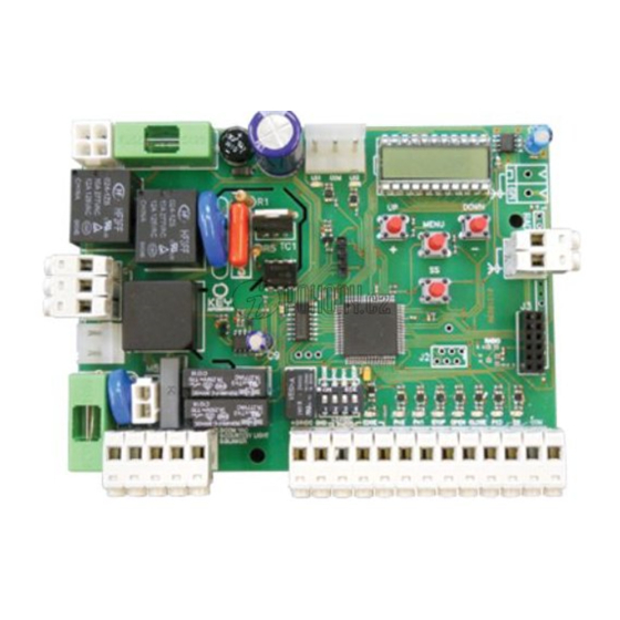
Steuergerät für einen motor 230 vac (120 vac), für schiebetor oder schwingtor;
Inhaltsverzeichnis

Werbung

Verfügbare Sprachen
  • DE

Verfügbare Sprachen

  • DEUTSCH, seite 50
Centrale per un motore 230 Vac (120 Vac), per cancello scorrevole o portone basculante
Control unit for a 230 Vac (120 Vac) motor, for a sliding gate or up-and-over door
Logique de commande pour un moteur 230 Vca (120 Vca), pour portail coulissant ou porte basculante
Central para un motor 230 Vca (120 Vca), para puerta de corredera o portón basculante
Steuergerät für einen Motor 230 Vac (120 Vac), für Schiebetor oder Schwingtor
Unidade para um motor 230 Vac (120 Vac), para portão de correr ou portão basculante
Centrala do silnika 230 Vac (120 Vac), napędzającego przesuwną bramę ogrodzeniową lub
Istruzioni ed avvertenze per l'installazione e l'uso
Instructions and warnings for installation and use
Instructions et avertissements pour l'installation et l'usage
Instrucciones y advertencias para su instalación y uso
Anleitungen und Hinweise zu Installation und Einsatz
Instruções e advertências para a instalação e utilização
Management
System
ISO 9001:2008
www.tuv.com
ID 9105043769
CT102
uchylną bramę garażową

Werbung

Inhaltsverzeichnis
loading

Inhaltszusammenfassung für Key Automation CT102

  • Seite 1 Anleitungen und Hinweise zu Installation und Einsatz Instruções e advertências para a instalação e utilização CT102 Centrale per un motore 230 Vac (120 Vac), per cancello scorrevole o portone basculante Control unit for a 230 Vac (120 Vac) motor, for a sliding gate or up-and-over door Logique de commande pour un moteur 230 Vca (120 Vca), pour portail coulissant ou porte basculante Central para un motor 230 Vca (120 Vca), para puerta de corredera o portón basculante...
  • Seite 2 INDICE Avvertenze per la sicurezza pag. 3 Introduzione al prodotto pag. 4 Descrizione della centrale pag. 4 Descrizione dei collegamenti pag. 4 Modelli e caratteristiche tecniche pag. 4 Elenco cavi necessari pag. 5 Verifiche preliminari pag. 5 Installazione del prodotto pag.
  • Seite 3: Avvertenze Per La Sicurezza

    KEY AUTOMATION si riserva il diritto di modificare le presenti istru- sostituito dal costruttore o dal suo servizio di assistenza tecnica o zioni qualora necessario, queste e/o versione superiore si possono...
  • Seite 4: Introduzione Al Prodotto

    2.1 - Descrizione della centrale di un display che permette una facile programmazione ed il costante La centrale CT102 è il più moderno ed efficiente sistema di controllo monitoraggio dello stato degli ingressi; inoltre la struttura a menù per i motori Key Automation per l’apertura e la chiusura elettrica di permette una semplice impostazione dei tempi di lavoro e delle logi- cancelli scorrevoli e portoni basculanti.
  • Seite 5: Verifiche Preliminari

    - Alimentazione protetta contro i cortocircuiti all’interno della centra- - Apprendimento automatico dei tempi di lavoro. le, sui motori e sugli accessori collegati. - Disattivazione degli ingressi di sicurezza tramite dip switch: non - Rilevamento degli ostacoli durante la velocità di regime mediante occorre ponticellare i morsetti relativi alla sicurezza non installata, è...
  • Seite 6: Installazione Del Prodotto

    4 - INSTALLAZIONE DEL PRODOTTO 4.1 - Collegamenti elettrici ATTENZIONE - Prima di effettuare i collegamenti verificare che la centrale non sia alimentata CONNETTORE ALIMENTAZIONI CONNETTORE MOTORE Fase alimentazione 230 Vac (120 Vac) 50-60 Hz Morsettiera collegamenti alimentazione Neutro alimentazione 230 Vac (120 Vac) 50-60 Hz Fase motore COM Vac Comune delle uscite “CR”...
  • Seite 7 4.2 - Fissaggio dei finecorsa per 900CT102I MIN 5 cm MIN 5 cm OPEN CLOSE ATTENZIONE! MIN 5 CM ATTENZIONE! MIN 5 CM LSI= 0 EL.F.=0 ATTENZIONE! EL.F.=0 4.3 - Schema elettrico elettrofreno...
  • Seite 8 CONNETTORE SICUREZZE E COMANDI +24 Vdc Alimentazione accessori positiva 24 Vdc, 250 mA Alimentazione accessori negativa PH-POW Alimentazione positiva fotocellule PH1, PH2; fototest selezionabile con parametro tph 24 Vdc, 250 mA EDGE Costa sicurezza, ON/OFF contatto NC o resistiva 8K2 tra EDGE e EDGE (attenzione, con dip switch 1 in ON disabilita ingresso sicurezza COSTA) Fotocellule (apertura) contatto NC tra PH2 e COM (attenzione, con dip switch 2 in ON disabilita ingresso sicurezza FOTOCEL- LULA 2).
  • Seite 9: Autoapprendimento Della Corsa

    Anomalie di funzionamento In questo paragrafo vengono elencate alcune anomalie di funzionamento che si possono presentare. ALLARME SOVRACCARICO IMPULSIVO La corrente del motore e’ incrementata molto rapidamente 1. Il cancello ha colpito un ostacolo. 2. Ci sono attriti sulla guida o sulla cremagliera. ALLARME COSTA SICUREZZA La centrale ha rilevato un segnale dalla costa sicurezza 1.
  • Seite 10 AUTOAPPRENDIMENTO DELLA CORSA E DEI PARAMETRI PRINCIPALI, CON RALLENTAMENTI PERSONALIZZATI 1. Sbloccare il cancello o la porta, portarlo in posizione centrale e ribloccarlo. 2. Entrare nel menù base per impostare il parametro LSI=P come da tabella al paragrafo 4.4. 3. Premere CONTEMPORANEAMENTE i tasti + e MENU per più di 5 secondi fino a visualizzare LOP e prepa- rarsi a premere (se necessario) il tasto DOWN (vedi figura).
  • Seite 11: Messa In Servizio

    PARAMETRI DESCRIZIONE DEFAULT UNITA’ Tempo richiusura automatica (0 = disabilitato) 20 *** Tempo richiusura dopo il transito (0 = disabilitato) % (step Forza motore (coppia a regime) da 10) Modalità rallentamento 0 = rallentamento 1/3 1 = rallentamento 2/3 Configurazione SBS: 0 = Normale (AP-ST-CH-ST-AP-ST…) 1 = Alternato STOP (AP-ST-CH-AP-ST-CH…) 2 = Alternato (AP-CH-AP-CH…)
  • Seite 12 6 - APPROFONDIMENTI - MENU AVANZATO Il MENU AVANZATO permette di personalizzare ulteriormente l’im- 5 secondi il tasto MENU pianto modificando dei parametri non accessibili dal menu base Per modificare i parametri del MENU AVANZATO si procede come Per accedere al menu AVANZATO si preme e si tiene premuto per indicato per il MENU BASE.
  • Seite 13 Key Automation non è però il produttore della vostra nare più a lungo possibile ed in completa sicurezza. Concordate automazione, che è invece il risultato di un’opera di analisi, valu- con il vostro installatore un piano di manutenzione con frequenza tazione, scelta dei materiali, e realizzazione dell’impianto eseguita...
  • Seite 14: Inhaltsverzeichnis

    TABLE OF CONTENTS Safety warnings pag. 15 Product Introduction pag. 16 Description of the control unit pag. 16 Description of the connections pag. 16 Models and technical characteristics pag. 16 List of cables required pag. 17 Preliminary Checks pag. 17 Installing the Product pag.
  • Seite 15: Safety Warnings

    1 - SAFETY WARNINGS should this occur, disconnect the power supply immediately and ATTENTION ! contact a Key Automation Service Centre. Use of the automation system in these conditions may cause hazards; ORIGINAL INSTRUCTIONS - important safety instructions. never place automation system components near to sources of heat Compliance with the safety instructions below is important for or expose them to naked lights.
  • Seite 16: Description Of The Control Unit

    Key Automation motors for the electric opening and closure times and operating modes. of sliding gates and up-and-over doors. All other, improper, use of the control unit is forbidden. The CT102 has SHIELD FUSE 2 MENU...
  • Seite 17: List Of Cables Required

    - Power supply with protection against short-circuits inside the con- - Automatic learning of working times. trol unit, on motors and on the connected accessories. - Safety device deactivation by means of dip switches: there is no - Obstacle detection during travel at normal speed by means of cur- need to bridge the terminals of safety devices which are not instal- rent sensor.
  • Seite 18: Product Installation

    4 - PRODUCT INSTALLATION 4.1 - Electrical connections WARNING - Before making the connections, ensure that the control unit is not powered up. POWER SUPPLY CONNECTOR MOTOR CONNECTOR Power supply live 230 Vac (120 Vac) 50-60 Hz Power supply connection terminal board Power supply neutral 230 Vac (120 Vac) 50-60 Hz Motor live COM Vac Common of the “CR”...
  • Seite 19: Limit Switch Fixing For 900Ct102I

    4.2 - Limit switch fixing for 900CT102I MIN 5 cm MIN 5 cm OPEN CLOSE CAUTION! MIN 5 CM CAUTION! MIN 5 CM LSI= 0 EL.F.=0 CAUTION! EL.F.=0 4.3 - Electrobrake wiring diagram...
  • Seite 20: Display During Normal Operation

    SAFETY AND CONTROL DEVICE CONNECTOR +24 Vdc Accessories power supply positive 24 Vdc, 250 mA Accessories power supply negative PH-POW Photocells PH1 and PH2 power supply positive; phototest can be selected with parameter tph 24 Vdc, 250 mA EDGE Safety sensor edge, ON/OFF NC contact or resistive 8K2 between EDGE and EDGE (warning, with dip switch 1 ON the safety EDGE input is off) Photocells (opening), NC contact between PH2 and COM (warning, with dip switch 2 ON the PHOTOCELL 2 safety device input is off) The photocell is tripped at any time during opening of the automation system, halting operation immediately;...
  • Seite 21: Autolearning Of The Travel Stroke

    Malfunctions This section lists a number of malfunctions which may occur. SURGE OVERLOAD ALARM The motor’s current drawdown has increased very quickly 1. The gate has struck an obstacle. 2. Friction on runners or rack. SAFETY EDGE ALARM The control unit has received a signal from the safety edge 1.
  • Seite 22: Customising The System - Basic Menu

    AUTOLEARNING OF THE TRAVEL STROKE AND MAIN PARAMETERS, WITH CUSTOMISED DECELERATIONS 1. Release the gate or door, move it onto the central position and lock it in place again. 2. Access the basic menu to set parameter LSI=P as shown in the table in point 4.4. 3.
  • Seite 23: Connecting The Radio Receiver

    DEFAULT PARAMETERS DESCRIPTION UNIT CONFIGURATION Automatic reclosure time (0 = off) 20 *** Reclosing time after transit (0 = off) % (step Motor force (peak torque) of 10) Deceleration mode 0 = 1/3 deceleration 1 = 2/3 deceleration SBS configuration: 0 = Normal (AP-ST-CH-ST-AP-ST…) 1 = Alternate STOP (AP-ST-CH-AP-ST-CH…) 2 = Alternate (AP-CH-AP-CH…)
  • Seite 24 6 - FURTHER DETAILS - ADVANCED MENU The ADVANCED MENU allows the system to be further customised down for 5 seconds by modifying parameters not accessible from the basic menu To modify ADVANCED MENU parameters, proceed as described To access the ADVANCED menu, press the MENU key and hold it for the BASIC MENU DEFAULT PARAMETERS...
  • Seite 25: Instructions And Warnings For The End User

    In the event of safety devices out of ser- Thank you for choosing Key Automation S.r.l.; please visit our Inter- vice arrange for repairs to the automation immediately;...
  • Seite 26 TABLE DES MATIÈRES Consignes de sécurité page 27 Présentation du produit page 28 Description de la logique de commande page 28 Description des branchements page 28 Modèles et caractéristiques techniques page 28 Liste des câbles nécessaires page 29 Vérifications préalables page 29 Installation du produit page 30...
  • Seite 27: Consignes De Sécurité

    KEY AUTOMATION se réserve le droit de modifier, si nécessai- Ce type d’interventions ne peut que causer des problèmes de fon- re, les présentes instructions, dont vous pouvez trouver sur le site ctionnement.
  • Seite 28: Présentation Du Produit

    2.1 - Description de la logique de commande dite. La CT102 est équipée d’un écran qui permet d’effectuer facile- La logique de commande CT102 est le système de commande le plus ment les opérations de programmation et de surveiller constamment moderne et le plus efficace pour les moteurs Key Automation destinés...
  • Seite 29: Liste Des Câbles Nécessaires

    - Alimentation protégée contre les courts-circuits à l’intérieur de la - Apprentissage automatique des temps de fonctionnement. logique de commande, sur les moteurs et sur les accessoires rac- - Désactivation des entrées de sécurité par commutateur DIP: il cordés. n’est pas nécessaire de shunter les bornes relatives au dispositif de - Détection des obstacles à...
  • Seite 30: Installation Du Produit

    4 - INSTALLATION DU PRODUIT 4.1 - Branchements électriques ATTENTION - Avant d’effectuer les branchements, vérifier que la logique de commande n’est pas sous tension. CONNECTEUR ALIMENTATIONS CONNECTEUR MOTEUR Phase alimentation 230 Vca (120 Vca) 50-60 Hz Bornier des branchements d'alimentation Neutre alimentation 230 Vca (120 Vca) 50-60 Hz Phase moteur COM Vac Commun des sorties CR et FLASH...
  • Seite 31: Fixation Des Dispositifs De Fin De Course Pour 900Ct102I

    4.2 - Fixation des dispositifs de fin de course pour 900CT102I MIN 5 cm MIN 5 cm OPEN CLOSE ATTENTION! MIN 5 CM ATTENTION! MIN 5 CM LSI= 0 EL.F.=0 ATTENTION! EL.F.=0 4.3 - Schéma de câblage électrofrein...
  • Seite 32: Visualisation En Mode Normal

    CONNECTEUR DISPOSITIFS DE SÉCURITÉ ET COMMANDES + 24 Vdc Alimentation accessoires positive 24 Vcc, 250 mA Alimentation accessoires négative PH-POW Alimentation positive photocellules PH1, PH2 ; photo-test sélectionnable avec le paramètre tph 24 Vcc, 250 mA EDGE Barre palpeuse de sécurité, ON/OFF contact NF ou résistive 8K2 entre EDGE et EDGE (attention : avec le commutateur DIP 1 sur ON, entrée de la BARRE PALPEUSE désactivée) Photocellules (ouverture) contact NF entre PH2 et COM (attention : avec le commutateur DIP 2 sur ON, entrée de la PHOTOCELLULE 2 désactivée).
  • Seite 33: Autoapprentissage De La Course

    Anomalies de fonctionnement Ce tableau énumère certaines anomalies de fonctionnement qui peuvent se présenter. ALARME SURCHARGE À RÉARME- Le courant du moteur a augmenté très rapidement MENT MANUEL 1. Le portail a heurté un obstacle. 2. Il y a des frottements sur le rail ou sur la crémaillère. ALARME BARRE PALPEUSE DE SÉCU- La logique de commande a détecté...
  • Seite 34: Personnalisation De L'installation - Menu De Base

    AUTOAPPRENTISSAGE DE LA COURSE ET DES PRINCIPAUX PARAMÈTRES, AVEC RALENTISSEMENTS PERSONNALISÉS 1. Débrayer le portail ou la porte, les mettre en position centrale puis les rebloquer. 2. Entrer dans le menu de base pour définir le paramètre LSI=P conformément au tableau de la section 4.4. 3.
  • Seite 35: Branchement Du Récepteur Radio

    PARAMÈTRES DESCRIPTION MIN. MAX. UNITÉ DÉFAUT Temps de la refermeture automatique (0 = désactivé) 20 *** Temps de la refermeture après le transit (0 = désactivé) % (pas Force moteur (couple de régime) de 10) Mode ralentissement 0 = ralentissement 1/3 1 = ralentissement 2/3 Configuration SBS : 0 = normal (AP-ST-CH-ST-AP-ST…)
  • Seite 36: Approfondissements- Menu Avancé

    6 - APPROFONDISSEMENTS- MENU AVANCÉ Le MENU AVANCÉ permet de personnaliser encore l’installation en Pour accéder au menu AVANCÉ, presser pendant 5 secondes la modifiant des paramètres qui ne sont pas accessibles à l’intérieur touche MENU du menu de base. Pour modifier les paramètres du MENU AVANCÉ, suivre les indica- tions fournies pour le MENU DE BASE PARAMÈTRES...
  • Seite 37: Instructions Et Avertissements

    été débrayé au moyen d’une clé de débrayage fournie avec l’installation. Avec les Nous vous remercions d’avoir choisi Key Automation S.r.l et vous dispositifs de sécurité hors d’usage, il est nécessaire de faire répa- invitons à...
  • Seite 38 ÍNDICE Advertencias para la seguridad pág. 39 Introducción al producto pág. 40 Descripción de la central pág. 40 Descripción de las conexiones pág. 40 Modelos y características técnicas pág. 40 Lista de los cables necesarios pág. 41 Controles preliminares pág. 41 Instalación del producto pág.
  • Seite 39: Advertencias Para La Seguridad

    Duran- KEY AUTOMATION se reserva la facultad de modificar estas in- te la instalación, evite que los líquidos puedan penetrar en el interior strucciones de ser necesario, esta versión o aquella superior se de los dispositivos;...
  • Seite 40: Introducción Al Producto

    2.1 - Descripción de la central tral CT102 incorpora una pantalla que permite programar fácilmente La central CT102 es el sistema de control más moderno y eficiente de y monitorizar de manera constante las entradas; además, la estruc- los motores Key Automation para la apertura y el cierre eléctrico de tura de menú...
  • Seite 41: Controles Preliminares

    - Alimentación protegida contra los cortocircuitos en el interior de la - Aprendizaje automático de los tiempos de funcionamiento. central, en los motores y en los accesorios conectados. - Desactivación de las entradas de seguridad mediante dip switch: - Detección de los obstáculos durante la velocidad de funciona- no es necesario puentear los bornes relativos al dispositivo de segu- miento mediante sensor de corriente.
  • Seite 42: Instalación Del Producto

    4 - INSTALACIÓN DEL PRODUCTO 4.1 - Conexiones eléctricas ATENCIÓN - Antes de realizar las conexiones, compruebe que la central no esté alimentada CONECTOR ALIMENTACIONES CONECTOR MOTOR Fase alimentación 230 Vca (120 Vca) 50-60 Hz Regleta de conexiones alimentación Neutro alimentación 230 Vca (120 Vca) 50-60 Hz Fase motor COM Vac Común de las salidas “CR”...
  • Seite 43 4.2 - Fijación del fin de carrera para 900CT102I MIN 5 cm MIN 5 cm OPEN CLOSE ATENCIÓN! MIN 5 CM ATENCIÓN! MIN 5 CM LSI= 0 EL.F.=0 ATENCIÓN! EL.F.=0 4.3 - Diagrama de cableado electrofreno...
  • Seite 44 CONECTOR DISPOSITIVOS DE SEGURIDAD Y MANDOS +24 Vdc Alimentación positiva de los accesorios 24 Vcc, 250 mA Alimentación negativa de los accesorios PH-POW Alimentación positiva de las fotocélulas PH1, PH2; fototest seleccionable con parámetro tph 24 Vcc, 250 mA EDGE Banda de seguridad, ON/OFF contacto NC o resistivo 8K2 entre EDGE y EDGE (atención, el dip switch 1 en ON inhabilita la entrada del dispositivo de seguridad BANDA) Fotocélulas (apertura) contacto NC entre PH2 y COM (atención, el dip switch 2 en ON inhabilita la entrada del dispositivo...
  • Seite 45 Irregularidades de funcionamiento En este apartado se mencionan algunas anomalías de funcionamiento que se pueden producir. ALARMA SOBRECARGA IMPULSIVA La corriente del motor aumenta muy rápido 1. La puerta ha golpeado un obstáculo. 2. Hay fricciones en la guía o en la cremallera. ALARMA BANDA DE SEGURIDAD La central ha detectado una señal de la banda de seguridad 1.
  • Seite 46 AUTOAPRENDIZAJE DE LA CARRERA Y DE LOS PARÁMETROS PRINCIPALES, CON RALENTIZACIONES PERSONALIZADAS 1. Desbloquee la puerta, colóquela en la posición central y bloquéela de nuevo. 2. Entre al menú básico para configurar el parámetro LSI=P como indicado en la tabla del apartado 4.4. 3.
  • Seite 47: Conexión Del Receptor

    PARÁMETROS DESCRIPCIÓN MÍN. MÁX. UNIDAD DEFECTO Tiempo cierre automático (0 = inhabilitado) 20 *** Tiempo cierre después de tránsito (0 = inhabilitado) % (paso de Fuerza del motor (par a régimen) Modo ralentización 0 = ralentización 1/3 1 = ralentización 2/3 Configuración SBS: 0 = Normal (AP-ST-CH-ST-AP-ST…) 1 = Alterno STOP (AP-ST-CH-AP-ST-CH…)
  • Seite 48 6 - DESCRIPCIÓN DETALLADA - MENÚ AVANZADO do durante 5 segundos el pulsador MENU El MENÚ AVANZADO permite personalizar aún más el sistema modi- ficando algunos parámetros a los que no se puede acceder desde el Para modificar los parámetros del MENÚ AVANZADO, proceda menú...
  • Seite 49 Key Automation aconseja un servicio cada 6 meses para un uso lización del sistema realizado por su instalador de confianza. Cada doméstico normal, pero dicha frecuencia puede variar en función...
  • Seite 50 INHALTSVERZEICHNIS Sicherheitshinweise S. 51 Einführung in das Produkt S. 52 S. 52 Beschreibung des Steuergerätes S. 52 Beschreibung der Anschlüsse S. 52 Modelle und technische Eigenschaften S. 53 Liste benötigter Kabel Vorabkontrollen S. 53 Produktinstallation S. 54 Elektrische Anschlüsse S. 54 Befestigung der anschläge für 900CT102I S.
  • Seite 51: Sicherheitshinweise

    Ist das Stromkabel beschädigt, muss es vom Hersteller, seinem werden. technischen Kundendienst oder einer ähnlich qualifizierten Person KEY AUTOMATION behält sich vor, diese Anweisungen notfalls zu ändern; diese Anweisungen und/oder eine neuere Version befinden ersetzt werden, um Gefährdungen zu vermeiden;...
  • Seite 52: Einführung In Das Produkt

    2 - EINFÜHRUNG IN DAS PRODUKT 2.1 - Beschreibung des Steuergerätes ten. Das CT102 ist mit einem Display ausgestattet, das eine einfache Das Steuergerät CT102 ist das modernste und effizienteste Steuer- Programmierung und kontinuierliche Überwachung des Status der system für Motoren von Key Automation zum elektrischen Öffnen und Eingänge erlaubt.
  • Seite 53: Liste Benötigter Kabel

    - Gegen Kurzschlüsse im Steuergerät, an den Motoren und am an- - Ausschaltung der Sicherheitseingänge durch Dip Switch: Die geschlossenen Zubehör geschützte Versorgung. Klemmen der nicht installierten Sicherheitsvorrichtungen müssen - Hinderniserkennung bei Betriebsgeschwindigkeit per Stromsensor. nicht überbrückt werden; es reicht aus, die Funktion mit Dip Switch - Automatisches Erlernen der Arbeitszeit.
  • Seite 54: Produktinstallation

    4 - PRODUKTINSTALLATION 4.1 - Stromanschlüsse ACHTUNG - Vor dem Anschluss sicherstellen, dass die Stromzufuhr des Steuergerätes abgeschaltet ist. STROMVERBINDER MOTORVERBINDER Phase 230 Vac (120 Vac) 50-60 Hz Klemmenleiste Versorgungsanschlüsse Nullleiter 230 Vac (120 Vac) 50-60 Hz Phase Motor COM Vac Gemeinsamer Leiter der Ausgänge „CR“ und „FLASH“ Gemeinsamer Leiter Motor Zusätzliche Beleuchtung, 230 Vac (120 Vac) 100 W, Phase Motor...
  • Seite 55: Befestigung Der Anschläge Für 900Ct102I

    4.2 - Befestigung der anschläge für 900CT102I MIN 5 cm MIN 5 cm OPEN CLOSE ACHTUNG! MIN 5 CM ACHTUNG! MIN 5 CM LSI= 0 EL.F.=0 ACHTUNG! EL.F.=0 4.3 - Electrobrake Schaltplan...
  • Seite 56: Anzeige Normalmodus

    VERBINDER FÜR SICHERHEITSVORRICHTUNGEN UND BEDIENELEMENTE +24 VDC Spannungsversorgung Zubehör positiv 24 VDC, 250 mA Spannungsversorgung Zubehör negativ PH-POW Positive Spannungsversorgung der Fotozellen PH1, PH2; Fototest wählbar über Parameter tph 24 VDC, 250 mA EDGE Sicherheitsleiste, ON/OFF NC-Kontakt oder Widerstandsleiste 8K2 zwischen EDGE und EDGE (Achtung: bei Dip Switch 1 auf ON wird der Eingang der Sicherheitsvorrichtung LEISTE gesperrt).
  • Seite 57: Einlernen Des Laufs

    Betriebsstörungen In diesem Absatz werden einige Betriebsstörungen aufgelistet, die auftreten können. ALARM IMPULSÜBERLAST Der Strom des Motors ist sehr schnell gestiegen 1. Das Tor ist auf ein Hindernis gestoßen. 2. An der Laufschiene oder Zahnstange sind Reibungen vorhanden. ALARM SICHERHEITSLEISTE Das Steuergerät hat ein Signal der Sicherheitsleiste erfasst 1.
  • Seite 58: Benutzerdefinierte Einrichtung Der Anlage

    EINLERNEN DES LAUFS UND DER HAUPTPARAMETER MIT BENUTZERDEFINIERTEN VERLANGSAMUNGEN 1. Das Tor oder die Tür entriegeln, in mittlere Stellung bringen und wieder anhalten. 2. Das Grundmenü zur Einstellung des Parameters LSI=P gemäß der Tabelle in Absatz 4.4 öffnen. 3. GLEICHZEITIG die Tasten + und MENU mehr als 5 Sekunden drücken, bis LOP angezeigt wird, und sich zum Drücken (falls nötig) der Taste DOWN bereithalten (siehe Abbildung).
  • Seite 59: Anschluss Des Funkempfängers

    PARAMETER BESCHREIBUNG STANDARD MIN. MAX. EINHEIT Automatische Wiederschließzeit (0 = deaktiviert) 20 *** Wiederschließzeit nach Durchfahrt (0 = deaktiviert) % (Schritt Motorkraft (Betriebsdrehmoment) von 10) Verlangsamungsmodus 0 = 1/3 Verlangsamung 1 = 2/3 Verlangsamung Konfiguration SBS: 0 = Normal (AP-ST-CH-ST-AP-ST…) 1 = Wechselweise STOPP (AP-ST-CH-AP-ST-CH…) 2 = Wechselweise (AP-CH-AP-CH…) 3 = Wohngebäude –...
  • Seite 60: Vertiefung - Erweitertes Menü

    6 - VERTIEFUNG - ERWEITERTES MENÜ Das ERWEITERTE MENÜ erlaubt durch Parameteränderungen, Sekunden lang drücken. die nicht im GRUNDMENÜ möglich sind, eine weitere Anpassung der Anlage an die persönlichen Bedürfnisse. Zur Änderung der Parameter des ERWEITERTEN MENÜS wie für das GRUNDMENÜ angegeben vorgehen. Für den Zugriff auf das ERWEITERTE Menü...
  • Seite 61: Anweisungen Und Hinweise Für Den Endbenutzer

    Hand vornehmen. Keinen Reparaturversuch vornehmen, wenden Sie sich an den Installateur Ihres Vertrauens: In der Zwischenzeit Wir danken Ihnen, dass Sie Key Automation S.r.l. gewählt haben, kann die Anlage nach der Entriegelung des Getriebemotors mit dem und laden Sie ein, für weitere Informationen unsere Internetseite entsprechenden Schlüssel, der zum Lieferumfang gehört, wie eine...
  • Seite 62 ÍNDICE Avisos sobre a segurança pag. 63 Informações sobre o produto pag. 64 Descrição da unidade pag. 64 Descrição das ligações pag. 64 Modelos e características técnicas pag. 64 Lista de cabos necessários pag. 65 Controlos preliminares pág. 65 Instalação do produto pág.
  • Seite 63: Avisos Sobre A Segurança

    É importante para a segurança das pessoas observar tactar o serviço de Assistência Key Automation. A utilização da au- as seguintes instruções de segurança. Conservar estas in- tomação nestas condições pode causar situações de perigo.
  • Seite 64: Informações Sobre O Produto

    2.1 - Descrição da unidade A CT102 está equipada com um ecrã que permite programar facil- A unidade CT102 é o mais moderno e eficiente sistema de controlo mente e monitorizar constantemente o status das entradas; além para os motores Key Automation para a abertura e o fecho elétrico de disso, a estrutura em menu permite configurar de forma simples os portões de correr e basculantes.
  • Seite 65: Controlos Preliminares

    - Alimentação protegida contra curto-circuitos dentro da unidade, - Autoaprendizagem dos tempos de trabalho. nos motores e nos acessórios ligados. - Desativação das entradas de segurança através de comutador - Deteção dos obstáculos durante a velocidade de funcionamento DIP: não é necessário ligar diretamente os bornes relativos à segu- através de sensor de corrente.
  • Seite 66: Instalação Do Produto

    4 - INSTALAÇÃO DO PRODUTO 4.1 - Ligações elétricas ATENÇÃO - Antes de fazer as ligações, verificar se a unidade não está ligada à alimentação elétrica. CONECTOR DAS ALIMENTAÇÕES CONECTOR DO MOTOR Fase da alimentação 230 Vac (120 Vac) 50-60 Hz Placa de bornes ligações alimentação Neutro da alimentação 230 Vac (120 Vac) 50-60 Hz Fase do motor...
  • Seite 67 4.2 - Fixação dos fins de curso para 900CT102I MIN 5 cm MIN 5 cm OPEN CLOSE ATENÇÃO! MIN 5 CM ATENÇÃO! MIN 5 CM LSI= 0 EL.F.=0 ATENÇÃO! EL.F.=0 4.3 - Diagrama de fiação Electrobrake...
  • Seite 68 CONECTOR SEGURANÇAS E COMANDOS +24 Vdc Alimentação dos acessórios positiva 24 Vdc, 250 mA Alimentação dos acessórios negativa PH-POW Alimentação positiva fotocélulas PH1, PH2; prova de sensibilidade selecionável com parâmetro tph 24 Vdc, 250 mA EDGE Barra de apalpação, ON/OFF contacto NC ou resistiva 8K2 entre EDGE e EDGE (atenção, com comutador DIP 1 em ON desabilita a entrada de segurança da BARRA) Fotocélulas (abertura) contacto NC entre PH2 e COM (atenção, com comutador DIP 2 em ON desabilita a entrada de segurança da FOTOCÉLULA 2).
  • Seite 69 Falhas de funcionamento Neste parágrafo estão indicadas algumas falhas de funcionamento que podem ocorrer. ALARME DE SOBRECARREGADA IM- A corrente do motor é aumentada muito rapidamente PULSIVO 1. O portão atingiu um obstáculo. 2. Há atrito no carril ou na cremalheira. ALARME BARRA DE APALPAÇÃO A unidade detectou um sinal da barra de apalpação 1.
  • Seite 70 AUTOAPRENDIZAGEM DO CURSO E DOS PARÂMETROS PRINCIPAIS, COM ABRANDAMENTOS PERSONALIZADOS 1. Desbloquear o portão ou a porta, deslocá-lo para a posição central e bloqueá-lo de novo. 2. Entrar no menu básico para configurar o parâmetro LSI=P de acordo com a tabela do parágrafo 4.4. 3.
  • Seite 71: Colocação Em Serviço

    PARÂMETROS DESCRIÇÃO DEFAULT MÍN. MÁX. UNIDADE Tempo fecho automático (0 = desabilitado) 20 *** Tempo fecho após passagem (0 = desabilitado) % (passo Força do motor (binário de funcionamento) de 10) Modo abrandamento 0 = abrandamento 1/3 1 = abrandamento 2/3 Configuração SBS: 0 = Normal (AP-ST-CH-ST-AP-ST…) 1 = Alternado STOP (AP-ST-CH-AP-ST-CH…)
  • Seite 72 6 - APROFUNDAMENTOS - MENU AVANÇADO O MENU AVANÇADO permite personalizar ainda mais o sistema premido durante 5 segundos a tecla MENU. modificando os parâmetros não acessíveis a partir do menu básico. Para modificar os parâmetros do MENU AVANÇADO seguir as Para aceder ao menu AVANÇADO, é...
  • Seite 73 Key Automation recomenda uma intervenção a cada 6 meses feita pelo seu instalador de confiança. Cada automação é única e para uma utilização doméstica normal, mas este período pode va-...
  • Seite 74 SPIS TREŚCI Uwagi dotyczące bezpieczeństwa str. 75 Informacje wstępne o produkcie str. 76 Opis centrali str. 76 Opis podłączeń str. 76 Modele i parametry techniczne str. 76 Wykaz niezbędnych przewodów str. 77 elektrycznych Kontrole wstępne str. 77 Montaż produktu str. 78 Podłączenia elektryczne str.
  • Seite 75: Uwagi Dotyczące Bezpieczeństwa

    KEY AUTOMATION zastrzega sobie prawo do modyfikowania ni- w przypadku stwierdzenia uszkodzenia przewodu elektrycznego, niejszej instrukcji w razie takiej potrzeby. Wersja aktualna, i/lub powinien on zostać wymieniony przez producenta, autoryzowany nowsze wersje instrukcji znajdują...
  • Seite 76: Informacje Ogólne

    2 - INFORMACJE OGÓLNE 2.1 - Opis centrali Zabrania się używania centrali niezgodnie z przeznaczeniem. Cen- Centrala CT102 jest najnowocześniejszym i najbardziej wydajnym sy- trala CT102 wyposażona jest w wyświetlacz ułatwiający czynności stemem sterowania silnikami Key Automation, służącymi do elektrycz- programowania oraz umożliwiający nieustanne monitorowanie stanu...
  • Seite 77: Wykaz Niezbędnych Przewodów Elektrycznych

    - Sposób zasilania chroniący przed zwarciem w obrębie centrali, - Automatyczne programowanie czasów pracy. w silnikach oraz w podłączonych urządzeniach dodatkowych. - Dezaktywowanie wejść bezpieczeństwa przy użyciu przełącznika. - Wykrywanie przeszkód przez czujnik prądowy podczas ruchu Brak konieczności montowania zworek na wejściach przeznaczony- o pełnej szybkości.
  • Seite 78: Montaż Produktu

    4 - MONTAŻ PRODUKTU 4.1 - Podłączenia elektryczne UWAGA – przed przystąpieniem do wykonywania podłączeń sprawdzić, czy do centrali nie jest doprowadzone zasilanie GNIAZDA ZASILANIA GNIAZDO SILNIKA Faza zasilania 230 Vac (120 Vac) 50-60 Hz Listwa zaciskowa do podłączenia zasilania Zero zasilania 230 Vac (120 Vac) 50-60 Hz Faza silnika COM VAC Wspólne wyjście „CR”...
  • Seite 79: Mocowanie Wyłącznika Krańcowego Dla 900Ct102I

    4.2 - Mocowanie wyłącznika krańcowego dla 900CT102I MIN 5 cm MIN 5 cm OPEN CLOSE UWAGA! MIN 5 CM UWAGA! MIN 5 CM LSI= 0 EL.F.=0 UWAGA! EL.F.=0 4.3 - Electrobrake schemat połączeń...
  • Seite 80: Wyświetlanie Normalnego Trybu Pracy

    GNIAZDO URZĄDZEŃ ZABEZPIECZAJĄCYCH I STEROWANIA +24 VDC Zasilanie urządzeń dodatkowych plusowe 24 VDC, 250 mA Zasilanie urządzeń dodatkowych minusowe PH-POW Zasilanie plusowe fotokomórek PH1, PH2; test fotokomórek wybierany jest za pomocą parametru tph 24 VDC, 250 mA EDGE Listwa bezpieczeństwa, ON/OFF kontaktowa NC lub oporowa 8K2 pomiędzy EDGE a EDGE (uwaga, ustawienie przełącznika 1 w położeniu ON powoduje dezaktywację...
  • Seite 81: Automatyczne Programowanie Przebiegu

    Nieprawidłowości działania W niniejszym paragrafie zostają wyszczególnione niektóre, mogące wystąpić nieprawidłowości dziania. ALARM PRZECIĄŻENIA IMPULSOWEGO Natężenie prądu w silniku gwałtownie wzrasta. 1. Brama napotkała na przeszkodę. 2. Tarcie na prowadnicy lub na listwie zębatej. ALARM LISTWA BEZPIECZEŃSTWA Centrala odebrała sygnał z listwy bezpieczeństwa. 1.
  • Seite 82: Indywidualne Dostosowanie Urządzenia - Menu Podstawowe

    AUTOMATYCZNE PROGRAMOWANIE PRZEBIEGU ORAZ ZASADNICZYCH PARAME- TRÓW, WRAZ Z INDYWIDUALNYM USTAWIENIEM PUNKTÓW ZWALNIAJĄCYCH 1. Odblokować bramę ogrodzeniową lub garażową, ustawić w centralnym położeniu i ponownie zablokować. 2. Otworzyć menu podstawowe w celu ustawienia parametru LSI=P zgodnie z tabelą w paragrafie 4.4. 3.
  • Seite 83: Podłączenie Odbiornika Radiowego

    USTAWIENIA PARAMETRY OPIS DOMYŚLNE MIN. MAKS. JEDNOSTKA Czas ponownego automatycznego zamknięcia (0 = 20 *** nieaktywny) Czas ponownego zamknięcia po wykonaniu przebiegu (0 = nieaktywny) % (krok z poz. Siła silnika (pełna wartość momentu) Tryb zwalniania 0 = zwalnianie 1/3 1 = zwalnianie 2/3 Konfiguracja SBS: 0 = Normalny (OTW-ST-ZAM-ST-OTW-ST…)
  • Seite 84 6 - ZAGADNIENIA ROZSZERZONE - MENU ZAAWANSOWANE MENU ZAAWANSOWANE umożliwia dalsze indywidualne dopaso- Aby uzyskać dostęp do menu ZAAWANSOWANEGO, wcisnąć wanie instalacji, poprzez zmianę parametrów niedostępnych w menu i przytrzymać przez 5 sekund przycisk MENU. Aby zmodyfikować podstawowym. parametry MENU ZAAWANSOWANEGO, stosować się do zaleceń obowiązujących dla MENU PODSTAWOWEGO.
  • Seite 85: Instrukcje I Ostrzeżenia Dla Użytkownika Końcowego

    • Konserwacja: Podobnie jak każdy inny mechanizm, automaty- bram ogrodzeniowych i garażowych, drzwi automatycznych, rolet ka wymaga przeprowadzania okresowej konserwacji. Zapewni to oraz szlabanów parkingowych i drogowych. Key Automation nie jest długie i bezpieczne działanie instalacji. Harmonogram okresowej jednakże wykonawcą Państwa całościowego systemu automatyki, konserwacji należy uzgodnić...
  • Seite 86 NOTE...
  • Seite 87: Dichiarazione Di Conformità

    Il sottoscritto Nicola Michelin, Amministratore Delegato dell’azienda The undersigned Nicola Michelin, General Manager of the company Key Automation srl, Via Alessandro Volta, 30 - 30020 Noventa di Piave (VE) – ITALIA dichiara che il prodotto tipo: declares that the product type: GO 230 Centrali di comando 230Vac o 120Vac per l’automazione di cancelli a 1 o 2 motori...
  • Seite 88 Key Automation S.r.l. Via Meucci - 30027 San Donà di Piave (VE) T. +39 0421.307.456 - F. +39 0421.656.98 Instruction version info@keyautomation.it - www.keyautomation.it 580ISCT102B REV.09...

Diese Anleitung auch für:

900ct102b900ct102b120900ct102i999ct102b

Inhaltsverzeichnis