Kessel EasyClean free Einbau- Und Betriebsanleitung
Vorschau ausblenden
Andere Handbücher für EasyClean free:
- Anleitung für einbau, bedienung und wartung (88 Seiten)
Inhaltsverzeichnis
Verfügbare Sprachen
Verfügbare Sprachen
Quicklinks
Einbau- und Betriebsanleitung
DE
........................................................................................................................ 2
EN
...................................................................................................................... 17
FR
...................................................................................................................... 33
IT
...................................................................................................................... 52
NL
...................................................................................................................... 72
PL
...................................................................................................................... 88
2020/06
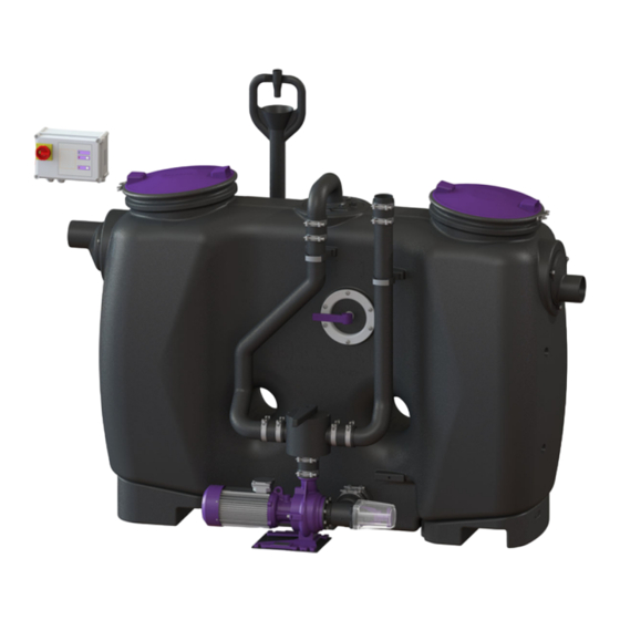
EasyClean free
Mix & Pump
016-189_01
Kapitel
Inhaltsverzeichnis

Verwandte Anleitungen für Kessel EasyClean free


Inhaltszusammenfassung für Kessel EasyClean free
- Seite 1 EasyClean free Mix & Pump Einbau- und Betriebsanleitung ........................2 ........................17 ........................33 ........................52 ........................72 ........................88 2020/06 016-189_01...
-
Seite 2: Inhaltsverzeichnis
Liebe Kundin, lieber Kunde, als Premiumhersteller von innovativen Produkten für die Entwässerungstechnik bietet KESSEL ganzheitliche Systemlösun- gen und kundenorientierten Service. Dabei stellen wir höchste Qualitätsstandards und setzen konsequent auf Nachhaltig- keit - nicht nur bei der Herstellung unserer Produkte, sondern auch im Hinblick auf deren langfristigen Betrieb setzen wir uns dafür ein, dass Sie und Ihr Eigentum dauerhaft geschützt sind. -
Seite 3: Hinweise Zu Dieser Anleitung
Hinweise zu dieser Anleitung Folgende Darstellungskonventionen erleichtern die Orientierung: Darstellung Erläuterung siehe Abbildung 1 Positionsnummer 5 von nebenstehender Abbildung Handlungsschritt in Abbildung Prüfen, ob Handsteuerung aktiviert wurde. Handlungsvoraussetzung OK betätigen. Handlungsschritt ✓ Anlage ist betriebsbereit. Handlungsergebnis siehe "Sicherheit", Seite 4 Querverweis auf Kapitel 2 Fettdruck besonders wichtige oder sicherheitsrelevante Information... -
Seite 4: Sicherheit
Der Betreiber der Anlage ist dazu verpflichtet: eine Gefährdungsbeurteilung zu erstellen, entsprechende Gefährdungszonen zu ermitteln und aus- zuweisen, Sicherheitsunterweisungen durchzuführen, gegen die Benutzung durch Unbefugte zu sichern. Person freigegebene Tätigkeiten an KESSEL-Anlagen Betreiber Sichtprüfung Sachkundiger (kennt, ver- Entleerung, Rei- steht Betriebsanweisung) nigung (innen),... -
Seite 5: Bestimmungsgemäße Verwendung
Bestimmungsgemäße Verwendung Das Produkt ist eine Anlage zum Abscheiden von Fett aus häuslichem oder gewerblichem Abwasser gemäß DIN EN 1825. Als Fette gelten Stoffe pflanzlichen und/oder tieri- schen Ursprungs mit einer Dichte unter 0,95 g/cm3, die teil- weise oder völlig wasserunlöslich oder verseifbar sind. Für den ordnungsgemäßen Betrieb müssen Entsorgungs- und Wartungszyklen, sowie die Bestimmungen zum Aufstellort eingehalten werden. -
Seite 6: Technische Daten
Technische Daten Maße und Gewichte Außenabmessungen a (mm) l (mm) b (mm) b1 (mm) h1 (mm) h2 (mm) h3 (mm) h4 (mm) 1500 1735 1055 1435 1765 1500 1735 1055 1435 1765 1880 2115 1055 1435 1765 1910 2145 1130 1185 1255 1655... - Seite 7 Angabe Wert Förderhöhe max. 17 m Förderleistung max. 60 m Förderguttemperatur (dauerhaft) max. 40 °C Anzugsdrehmoment Beschreibung / Verwendung Drehmoment Nm Schlüsselweite PT-Schraube KB60x30 WN 1411 4,5 ±0,5 PT-Schraube 100x30 A2 Befestigungsschelle (Fülleinrichtung) ISK 10mm Rohrschelle D=120 8-10 Nuss 13mm Rohrschelle D=84 8-10 Nuss 13mm...
-
Seite 8: Montage
Montage Transporthinweis Zur leichteren Einbringung kann die Pumpe und die Verrohrung demontiert werden. Nach Wiederanbringung der Pumpe und der Verrohrung muss eine Dichtheitsprüfung durchgeführt werden. Transport mit Gabelstapler! Beim Transport mit einem Gabelstapler sollte die Pumpe an den Rohrschellen der Spülleitung und der Verbindung zum Behälter demontiert werden, um starke Belastung auf den Schweißnähten an der Verbindung der Pumpe zum Behälter zu vermeiden. -
Seite 9: Rohrleitungen Montieren
Rohrleitungen montieren Zu- und Auslauf anschließen Anschluss von Zu- und Auslauf an bauseitiges Entwässe- rungssystem. Sollen die Anschlüsse gegenseitig getauscht werden, diese jeweils zusammen mit den Schrauben (1) und Dichtungen (2) demontieren und entsprechend tau- schen. Sicherstellen, dass die Dichtungen (3) ausrei- chend gefettet sind. -
Seite 10: Elektrische Anschlüsse Herstellen
Funktionsprüfung (siehe "Funktionsprüfung", Seite 11) durchführen. Zubehörteile montieren Storz B Kupplung anschließen Storz B Kupplung an bauseitige Steigleitung/Entsorgungsleitung anschließen. Falls die Storz B Kupplung in einiger Entfernung außerhalb des Gebäudes platziert werden soll, kann hierfür der KESSEL-Entsorgungsschacht (Zubehör) verwendet werden. 10 / 112 016-189_01... -
Seite 11: Inbetriebnahme
Inbetriebnahme Vorbereiten der Inbetriebnahme Ggf. Wasserversorgung herstellen. Abscheider mit Kaltwasser bis zum Ruhepegel (Höhe des Auslaufs) auffüllen, sofern nicht bereits geschehen. Generalinspektion durchführen lassen (bei Erstinbetriebnahme, danach alle 5 Jahre). Schaltgerät einschalten Stromversorgung herstellen. Hauptschalter auf Position "ON" stellen. ✓ Schaltgerät startet selbsttätig. Initialisierung des Schaltgerätes Hauptschalter aus- und wieder einschalten. -
Seite 12: Entsorgung
Entsorgung Entsorgung durchführen Teilentleeren Saugschlauch des Entsorgungsfahrzeugs an Storz B Kupplung anschließen. Stellventil auf Position LEEREN (Pfeil rechts) drehen. Handbetrieb am Schaltgerät starten. Abwarten, bis 1/3 des Ruhepegels abgepumpt ist. Dauer ist abhängig von Nenngröße. Handbetrieb am Schaltgerät pausieren. Mischen Stellventil auf Position SPÜLEN (Pfeil links) drehen. -
Seite 13: Wartung
Wartung Intervall Generalinspektion An dieser Anlage muss gemäß DIN EN 1825 alle 5 Jahre eine Generalinspektion (u. a. Dichtheitsprüfung) durchgeführt werden. Wartungsintervall und -tätigkeiten Die Anlage ist jährlich durch einen Sachkundigen zu warten. Folgende Tätigkeiten sind im Rahmen der Wartung durchzuführen: Entsorgung durchführen. -
Seite 14: Betriebszustände
Hilfe bei Störungen Blinkmuster und Bedienoberfläche Blinken Leuchten / Eingeschaltet Ausgeschaltet Blinken im Wechsel Blinken gleichzeitig Power LED (grün) Taste Alarm LED Alarm (rot) Taste Handbetrieb LED Handbe- trieb (orange) Signalton Beschreibung Maßnahme orange grün (1) rot (2) Betriebszustände Netzausfall Netzspannung wiederherstellen Betriebsbereit Alarmzustände / Fehler... -
Seite 15: Abhilfemaßnahmen
Hilfe bei Störungen (Pumpe) Störung Ursache Maßnahme(n) Pumpe läuft nicht an, zu geringe Leis- Motorschutzschalter hat ausgelöst Ausschalten und abwarten, bis Pumpe tung abgekühlt ist, dann erneut versuchen. Motor ist blockiert Blockade entfernen / Pumpe warten (Sicherheitshinweise beachten). Motor dreht zu schwer Netzanschluss auf Phasenausfall prü- fen. -
Seite 16: Werksabnahme, Prüfungen
Werksabnahme, Prüfungen Anlagenpass 16 / 112 016-189_01... - Seite 17 Für Sie ist es wichtig, die Qualität und Funktionsfähigkeit Ihrer Anlage immer auf dem besten Stand zu halten, gerade wenn es um die Voraussetzung für eine Gewährleistung geht. Wenn Sie die Wartung über KESSEL durchführen lassen, gewähr- leisten wir Ihnen eine ständige Aktualisierung und Pflege Ihrer Anlage.
- Seite 110 110 / 112 016-189_01...
- Seite 111 016-189_01 111 / 112...
- Seite 112 Registrieren Sie Ihr Produkt online, um von einer schnelleren Hilfe zu profitieren! http://www.kessel.de/service/produktregistrierung.html KESSEL AG, Bahnhofstr. 31, 85101 Lenting, Deutschland...