Herunterladen Diese Seite drucken
Kessel Comfort PLUS Einbau- Und Betriebsanleitung
Vorschau ausblenden Andere Handbücher für Comfort PLUS:

Werbung

Verfügbare Sprachen
  • DE

Verfügbare Sprachen

  • DEUTSCH, seite 1
2020/05
Schaltgerät Comfort
Schaltgerät Comfort
Schaltgerät Comfort
PLUS
PLUS
PLUS
Einbau- und Betriebsanleitung
DE
Einbau- und Betriebsanleitung..........................2
EN
Installation and operating manual...................35
FR
Instructions de pose et d'utilisation.................71
IT
Istruzioni per l'installazione e l'uso............... 108
NL
Inbouw- en montagehandleiding...................144
PL
Instrukcja zabudowy i obsługi....................... 180
010-700_03

Werbung

loading

Inhaltszusammenfassung für Kessel Comfort PLUS

  • Seite 1 Schaltgerät Comfort Schaltgerät Comfort Schaltgerät Comfort PLUS PLUS PLUS Einbau- und Betriebsanleitung Einbau- und Betriebsanleitung Einbau- und Betriebsanleitung Einbau- und Betriebsanleitung......2 Installation and operating manual....35 Instructions de pose et d’utilisation....71 Istruzioni per l’installazione e l’uso....108 Inbouw- en montagehandleiding....144 Instrukcja zabudowy i obsługi....... 180 2020/05 010-700_03...
  • Seite 2: Inhaltsverzeichnis

    Inhalt Liebe Kundin, lieber Kunde, als Premiumhersteller von innovativen Produkten für die Hinweise zu dieser Anleitung........Entwässerungstechnik bietet KESSEL ganzheitliche Sys- Sicherheit..............temlösungen und kundenorientierten Service. Dabei stel- Technische Daten............ len wir höchste Qualitätsstandards und setzen konsequent auf Nachhaltigkeit - nicht nur bei der Herstellung unserer Montage..............
  • Seite 3: Hinweise Zu Dieser Anleitung

    Hinweise zu dieser Anleitung Zeichen Bedeutung Folgende Darstellungskonventionen erleichtern die Orientie- Gerät freischalten! rung: Darstellung Erläuterung Gebrauchsanweisung beachten siehe Abbildung 1 Positionsnummer 5 von nebenstehender Abbildung CE-Kennzeichnung Handlungsschritt in Abbildung Warnung Elektrizität Prüfen, ob Hand- steuerung aktiviert Handlungsvoraussetzung wurde. WEEE-Symbol, Produkt unterliegt RoHS-Richtlinie OK betätigen.
  • Seite 4: Sicherheit

    Sicherheit Das Schaltgerät sowie die Schwimmer bzw. Niveausteue- rung stehen unter Spannung und dürfen nicht geöffnet wer- Allgemeine Sicherheitshinweise den. Es ist sicherzustellen, dass sich die Elektrokabel sowie alle Die Anleitungen der Anlage und Anlagenbestandteile sowie anderen elektrischen Anlagenteile in einem einwandfreien die Wartungs- und Übergabeprotokolle sind an der Anlage Zustand befinden.
  • Seite 5: Bestimmungsgemäße Verwendung

    Sicherheitsunterweisungen durchzuführen, gegen die Benutzung durch Unbefugte zu sichern. Person freigegebene Tätigkeiten an KESSEL-Anlagen Betreiber Sichtprüfung, Inspektion Sachkundiger, (kennt, ver- Funktionskontrolle, Konfi- steht Betriebsanweisung) guration des Schaltgerätes Elektrofachkraft VDE 0105 (nach Vor- Arbeiten an elektri- schriften für elektr. Sicherheit, oder...
  • Seite 6: Produktbeschreibung

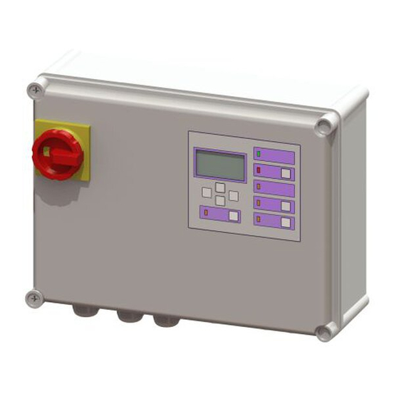
    Produktbeschreibung Abb. 2: Display und Bedienfeld LED Alarm Abb. 1: Funktionskomponenten LED Niveauüberschreitung Hauptschalter Handbetrieb Pumpe 1/2 Display und Bedienfeld Motorisierte Klappe auf-/zufahren Typenschild Display mit Fehlermeldungsanzeige Kabeldurchführungen, Anschlüsse Zusätzliche Angaben zur ATEX-Ausführung Die Anforderungen der Normen EN II (1) GD [Ex ia Ga] IIC 50014 + A1-A2, EN 50020:2002 werden erfüllt.
  • Seite 7 Maximale Leistungsauf- 11 VA Mono- / 15 VA Duo- Technische Spezifikation (Einzelbarriere) nahme Anlagen Höchstwerte*: (Klemmen N, L1, L2, L3, PE) Drehstrom 230 V (AC) / 50 28 V Hz +- 10% zur Versorgung der Elektronik 93 mA Eingangsstromkreise Thermoeingänge Un = 230V 300 Ω...
  • Seite 8: Technische Daten

    Technische Daten Angabe Comfort PLUS 230V Comfort PLUS 400V Maximale Leistung (kW) am Schaltausgang (bei cos φ = 1) Nennstrombereich 4,0 - 6,3 A 6,3 - 10 A 2,5 - 4,0 A 4,0 - 6,3 A 6,3 - 10 A...
  • Seite 9: Montage

    Montage Sicherheitshinweise beachten, siehe "Sicherheit", Anschlussübersicht Netzleitung Seite 4. Für eine Übersicht der Platinenanschlüsse, siehe Quelle Anschluss Leitungsart Kennung Anschluss "Anschlusspläne" . Kabel -bez. Schaltgerät montieren Schutzleiter Gelb-grün PE WARNUNG Neutralleiter Blau Anlage freischalten! Sicherstellen, dass Leitungen Netz 5-adrig Phase und elektrische Komponenten während der Arbeiten von der Spannungsversorgung getrennt sind.
  • Seite 10 Netzleitung 230V Netzleitung ist steckerfertig. ATEX-Anforderung sicherstellen Damit die Pumpen in explosionsgefährdeter Umgebung betrieben werden dürfen, müssen bei der elektrischen Instal- lation folgende zusätzliche Anforderungen berücksichtigt werden. Leitungsquerschnitt Die Netzleitungen zum Schaltgerät benötigen einen Min- destquerschnitt von 6 mm oder entsprechend der erforderli- chen Absicherung, je nachdem welcher Querschnitt höher ist (siehe "Technische Daten", Seite 8).
  • Seite 11: Abwasserpumpe(N) Anschließen

    Platinenanschlüsse für die Abwasserpumpe(n) (ATEX) U1, V1, W1 (U2, V2, W2 ): Phasen PE: Schutzleiter TF2: Temperaturüberwachung Abwasserpumpe(n) anschließen Vor Anschließen der Pumpe prüfen, ob der Motorschutz- schalter des Schaltgerätes für die Stromaufnahme der Pumpe(n) (siehe Typenschild) geeignet ist. Ggf. Motorschutzschalter auf den Nennstrom der Pumpe einstellen (siehe Typenschild der Pumpe).
  • Seite 12: Sensorik Und Steuerung Anschließen

    Sensorik und Steuerung anschließen Eine Anschlussübersicht der Platine finden Sie am Ende die- ses Kapitels. Alarmsonde Sondenkabel Alarmsonde (rote Markierung) heranführen. Schutzkappe(n) abziehen. Phönixkontaktstecker auf Anschluss schieben (Pfeil nach oben). Phönixkontaktstecker mit Schraubenschlüssel (15mm) festziehen. Abb. 3: Phönixkontaktstecker anschließen Drucksensor Soll ein Drucksensor zur Ermittlung des Füllstandes verwen- det werden, diesen wie folgt anschließen.
  • Seite 13 Druckschlauch unter Zuhilfenahme einer Einzugsspi- rale durch das Kabelleerrohr hindurchführen, dazu das Schlauchende mit Verschlusskappe an der Einzugsspirale befestigen. Schwimmerschalter Sollen Schwimmerschalter zur Ermittlung des Füllstandes verwendet werden, wie folgt vorgehen: Blindstopfen (1) herausziehen. M16-Kabelverschraubung einstecken und mit Gegenmut- Druckschlauchende mit Verschlusskappe passgenau ter befestigen.
  • Seite 14 Mono- und Duo-Anlagen gleich. Aderfarbe Bez. auf Platine Klemmenfarbe (-)Schwarz blau Probe2 (+)Rot schwarz Anschlussübersicht Pegelsonde Beim Verlängern der Anschlussleitung der Pegelsonde Abb. 4: Schwimmerschalter Mono (nicht-ATEX) KESSEL-Klemmdose (Art. Nr. 28799) verwenden. Abb. 5: Schwimmerschalter Duo (nicht-ATEX) 14 / 220 010-700_03...
  • Seite 15: Bezeichnung

    USB-Anschluss herausführen Damit der USB-Anschluss auf der Platine ohne ein Öffnen des Gehäuses zugänglich wird, kann eine USB-Gehäuse- buchse mit Kabel und Stecker zum Einbau in das Gehäuse des Schaltgerätes bei KESSEL bestellt werden (Art. Nr. 28785). 010-700_03 15 / 220...
  • Seite 16 Diverses Zubehör - Comfort Schaltgeräte Fernsignalgeber Art. Nr. 20162 Warnleuchte Art. Nr. 97715 16 / 220 010-700_03...
  • Seite 17 Anschlusspläne Abb. 6: Anschlussplan 400V (6-adrig) 010-700_03 17 / 220...
  • Seite 18 Abb. 7: Anschlussplan 400V (9-adrig) 18 / 220 010-700_03...
  • Seite 19 Abb. 8: Anschlussplan 230V (3-adrig) 010-700_03 19 / 220...
  • Seite 20 Abb. 9: Anschlussplan 400V (ATEX mit Potentialausgleich) 20 / 220 010-700_03...
  • Seite 21: Erstinbetriebnahme

    Erstinbetriebnahme Netzspannung herstellen (230V Schaltgeräte) Batterie anschließen Schukostecker in die dafür vorgesehene Steckdose ein- Stecker (2) der Batterie(n) anschließen. stecken. Hauptschalter (1) in Position ON bringen. Initialisierung startet selbsttätig. Gerät prüft elektrische Bauteile. Spannungsprüfung der Notstrom-Batterien. Menüpunkt wird angezeigt. |3.10. Sprache| Einschalten Hauptschalter (1) in Position ON drehen.
  • Seite 22: Übersicht Konfigurationsmenü

    ► Landessprache mit den Pfeiltasten auswählen und mit OK Übersicht Konfigurationsmenü bestätigen. ✓ Menü erscheint. |Datum/Uhrzeit| Datum / Uhrzeit ► Die jeweils blinkende Ziffer in Datum und Uhrzeit einstel- len und mit OK bestätigen. ✓ Menü erscheint. |Produkttyp| Produkttyp ► Produkttyp auswählen und mit OK bestätigen. Auswahl hat Auswirkung darauf, welche Einstellmöglich- Die Ordnungszahl des Menüpunktes wird in keiten verfügbar sind.
  • Seite 23 Wartungsintervall ► Eingabe des normativ vorgegebenen Wartungsintervalles. ✓ Initialisierung ist abgeschlossen, Schaltgerät ist betriebs- bereit. Menütexte Comfort PLUS Systemsteuerung Informationen Betriebsstunden 1.1.1 Gesamtlaufzeit 0 - 999,999,9 1.1.2 Laufzeit Pumpe 1 0 - 999,999,9 1.1.3 Schaltspiele Pumpe 1 0 - 999,999,9 1.1.4...
  • Seite 24 Aktuelle Messwerte 1.5.1 Netz-Strom 0 - 99,9 1.5.2 Batteriespannung 0 - 99,9 1.5.3 Niveau 0 - 5000 1.5.4 Netz-Spannung 0 - 99,9 1.5.5 Temperatur °C -9 - 99° 1.5.6 Klappe Strom 0 - 99,9 Parameter 1.6.1 Einschaltverzögerung 0 - 99 1.6.2 Nachlaufzeit Zugangscode: 1000...
  • Seite 25 1.6.14 EIN 2 Niveau 0 - 5000 1.6.15 AUS 2 Niveau 0 - 5000 1.6.16 Einschaltverzögerung Klappe 0 - 99 1.6.17 Nachlaufzeit 0 - 99 1.6.18 Max. Strom Klappe 150 - 200 1.6.19 S1/S3 Pumpenbetrieb 1 - 999 Wartung Handbetrieb 2.1.1 Pumpe 1 2.1.2...
  • Seite 26: Wartung Durchgeführt

    Wartung durchgeführt Wartungsintervall 2.6.1 3 Monate 2.6.2 6 Monate 2.6.3 12 Monate 2.6.4 Manuelle Wartungsintervallein- gabe 2.6.5 kein Wartungsintervall Freischalt. RemoteControl 2.7.1 Freischaltdauer Kalibrierung Drucksensor Einstellungen Parameter 3.1.1 Einschaltverzögerung 0 - 99 3.1.2 Nachlaufzeit 0 - 99 3.1.3 Max. Strom 3,5 - 99 Zugangscode: 1000 3.1.4...
  • Seite 27 3.1.11 EIN 1 Niveau 0 - 5000 3.1.12 AUS 1 Niveau 0 - 5000 3.1.13 ALARM - NIveau 0 - 5000 3.1.14 EIN 1 Niveau 0 - 5000 3.1.15 AUS 2 Niveau 0 - 5000 3.1.16 Einschaltverzögerung Klappe 0 - 99 3.1.17 Nachlaufzeit Klappe 0 - 99...
  • Seite 28 Anlagenvariante 3.6.1 1 Motorklappe 3.6.2 2 Motorklappen 3.6.5 F Compact 3.6.6 3.6.7 F XL 200l 3.6.8 F XL 300l 3.6.9 F XL 450l 3.6.10 S Unterflur 3.6.11 Sonder-Hebeanlage Mono 3.6.12 F Compact Duo 3.6.13 F Duo 3.6.14 F XL 200l Duo 3.6.15 F XL 300l Duo 3.6.16...
  • Seite 29: Leistungsgröße

    3.6.23 F AP 501 Mono LW 800 3.6.24 F AP 501 Mono LW 1000 3.6.25 F (ohne ATEX) 3.6.26 S Schacht LW 600 Mono 3.6.27 S Schacht LW 1000 Mono 3.6.28 Sonder-Pumpstation ohne ATEX 3.6.29 Sonder-Pumpstation ATEX 3.6.30 FXL Duo (ATEX) 3.6.31 S Duo 3.6.33...
  • Seite 30 3.7.3 SPF 1400 (230V) 3.7.4 SPF 1500 (400V) 3.7.5 SPF 3000 (400V) 3.7.6 SPF 4500 (400V) 3.7.7 SPF 5500 (400V) 3.7.8 1,9 kW 3.7.9 1,3 kW 3.7.10 Ama Porter 3.7.11 230V / 2,5 - 4 A 3.7.12 230 V / 4 - 6,3 A 3.7.13 230 V / 6,3 - 10 A 3.7.14...
  • Seite 31 3.7.29 GTF/GTK5200 3.7.50 Sonderpumpe Sensorkonfiguration 3.8.1 Drucksensor + Optische Sonde 3.8.2 Drucksensor 3.8.3 Drucksensor + Alarmschwim- 3.8.4 Drucksensor + Lufteinperlung 3.8.5 Pegelsonde 3.8.6 Pegelsonde + Alarmschwimmer 3.8.7 Schwimmer 3.8.8 Schwimmer ohne Aus-Niveau Kommunikation 3.9.1 Direktverbindung 3.9.2 GSM-Modem 3.9.2.1 Stationsname Zugangscode: 1000 3.9.2.2 Eigene Nummer 3.9.2.3 Modemtyp 3.9.2.4 PIN...
  • Seite 32 3.9.2.9 Status 3.9.3 Modbus 3.9.3.1 Einstellungen Modbus 3.9.3.2 Modbus aktivieren 3.9.3.3 Geräteadresse 3.9.3.4 Baudrate 3.9.3.5 Stoppbit 3.9.3.6 Parität 3.9.4 Remote Control 3.9.4.1 Remote Control aktivieren 3.9.4.2 Freischaltdauer 3.10 Sprache 3.10.1 Deutsch 3.10.2 English 3.10.3 Francais 3.10.4 Italiano 3.10.5 Nederlands 3.10.6 Polski 3.11 Rücksetzen...
  • Seite 33 3.12.4 TP-Konstante 0-9999 3.12.5 Schwelle Batterie 0-18 3.12.6 Drehfeld ein/aus 3.12.7 Alternierender Betrieb ein/aus 3.12.8 Zähler rücksetzen 3.12.9 AC-Ausgang ein/aus 3.12.10 DC-Ausgang ein/aus 3.12.11 SMS-Intervall wöchentlich/täglich/stündlich 3.12.12 OPT Fehlererk. Zeit 0-30 3.12.13 OPT Logik Zeit 0-30 3.12.14 Trockenlaufschutz ein/aus 3.12.15 Druckfehler Grenze 5-99 3.12.16 Offset Drucksensor (+/-)30...
  • Seite 34: Speicherung Druckabfall

    3.12.24 Speicherung Druckabfall ein/aus Datenübertragung Daten auslesen Software updaten Parameter einlesen Wartung Update und Daten auslesen Externe Festplatten dürfen nicht angeschlossen werden, das Schaltgerät funktioniert dann nicht (max. 100 mA Stromver- sorgung). Der USB-Stick muss vor der Benutzung über einen Win- dows-PC mit FAT formatiert und ein Name zugewiesen wor- den sein.
  • Seite 35 ACHTUNG Daten auslesen Anlage freischalten! USB-Stick anschließen. aus- Sicherstellen, dass die elektrischen Komponen- |Daten auslesen| wählen und mit OK bestäti- ten während der Arbeiten von der Spannungsver- sorgung getrennt sind. gen. Eine Datei mit den Sys- temdaten wird auf den USB- Hauptschalter (1) am Schaltgerät in Position OFF bringen, Stick gespeichert (*.csv).
  • Seite 36: Ihre Kessel Ag Bahnhofstraße

    Technical data............Dear customer, As a premium manufacturer of innovative products for drain- Installation..............ing technology, KESSEL offers integrated system solutions Initial commissioning..........and customer-oriented service. In doing so, we set the high- Maintenance............est quality standards and focus firmly on sustainability - not...
  • Seite 37 Notes on this manual Icon Meaning The following conventions make it easier to navigate the Isolate device! manual: Symbol Explanation Observe the instructions for use See Figure 1 Position number 5 from the adjacent figure CE marking Action step in figure Check whether Warning, electricity manual control...
  • Seite 38: General Safety Notes

    Safety The control unit and the float switch or level control are live and must not be opened. General safety notes It must be ensured that the electric cables as well as all other electrical system components are in a faultless condition. In The manuals for the system and parts thereof as well as the case of damage, the system may on no account be put into maintenance records and handover certificates must be kept...
  • Seite 39: Intended Use

    Person Approved activities on KESSEL systems Operating company Visual inspec- tion, inspection Technical expert, (familiar with, Functional check, config- understands operating instructions) uration of the control unit Electrical specialist VDE 0105 (per regulations Work on electri- for electrical safety, or per national equivalents) cal installation 1) Operation and assembly work may only be carried out by persons who are 18 years of age.
  • Seite 40: Product Description

    Product description Fig. 2: Display and control panel LED Alarm Fig. 1: Functional components LED level exceedance Main switch Manual operation, pump 1/2 Display and control panel Open/close motorised flap Type plate Display with error messages Cable passages, connections Additional information on ATEX design The requirements of the standards II (1) GD [Ex ia Ga] IIC EN 50014 + A1-A2, EN 50020:2002...
  • Seite 41 Maximum power consump- 11 VA Mono / 15 VA Duo Technical specification (single barrier) tion systems 28 V (terminals N, L1, L2, L3, PE) Three-phase current 230 V 93 mA (AC) / 50 Hz +- 10% for sup- ply of the electronics 300 Ω...
  • Seite 42: Technical Data

    Technical data Item Comfort PLUS 230V Comfort PLUS 400V Maximum power (kW) at the switch output (if cos φ = 1) Nominal current range 4.0 - 6.3 A 6.3 - 10 A 2.5 - 4.0 A 4.0 - 6.3 A 6.3 - 10 A...
  • Seite 43: Installing The Control Unit

    Installation Follow the safety instructions, see "Safety", page 38. For an Connection overview for the mains cable overview of the printed circuit board connections, see "Con- Source Connec- Type of Label Connec- nection diagrams", page 52 . tion conduc- tion Installing the control unit Cables name...
  • Seite 44 ATEX pump connection with equipotential bonding An earthing cable of at least 4mm must be connected to the submersible pump for the equipotential bonding according to EN 60079-14. The earthing cable is routed between the (self-locking) earthing screw and the screw retainer on the terminal.
  • Seite 45 Printed board connections for the wastewater pump(s) (ATEX) U1, V1, W1 (U2, V2, W2 ): Phases PE: protective conductor TF2: temperature monitoring Connecting the wastewater pump(s) Before connecting the pump, check whether the motor protection switch of the control unit is suitable for the power consumption of the pump(s) (see type plate).
  • Seite 46 Connect sensors and control A connection overview of the printed boards is given at the end of this chapter. Alarm probe Lay the alarm probe sensor cable (red marking). Remove protective cap(s). Push the Phoenix contact connector onto the connection (arrow pointing upwards).
  • Seite 47 With the help of a spiral cable puller, feed the pressure hose through the conduit pipe; to do so, fix the end of the hose with end cap on the spiral cable puller. Cut off the end of the pressure hose with end cap to fit precisely.
  • Seite 48 Fig. 4: Mono float switch (non-ATEX) Float switch If float switches are to be used for level detection, proceed as follows: Pull out blind plugs (1). Insert M16 cable gland and fix with locknut. Pull through cable and tighten nut. Connect the cable ends of the float switches to the termi- nals shown.
  • Seite 49 Name on PCB Terminal colour (-)Black blue Probe2 (+)Red black Overview of connections for the level sensor Use KESSEL junction box (art. no. 28799) to lengthen the connection cable of the level sensor. Installation and operating manual 010-700_02 49 / 220...
  • Seite 50 To ensure that the USB connection on the printed board can be accessed without opening the housing, a USB housing socket with cable and connector for installation in the hous- ing of the control unit can be ordered from KESSEL (art. no. 28785). Installation and operating manual...
  • Seite 51 Diverse accessories - control units Comfort External audible alarm art. no. 20162 Warning beacon art. no. 97715 Installation and operating manual 010-700_02 51 / 220...
  • Seite 52: Connection Diagrams

    Connection diagrams Fig. 6: 400V connection diagram (6-wire) Installation and operating manual 52 / 220 010-700_02...
  • Seite 53 Fig. 7: 400V connection diagram (9-wire) Installation and operating manual 010-700_02 53 / 220...
  • Seite 54 Fig. 8: 230V connection diagram (3-wire) Installation and operating manual 54 / 220 010-700_02...
  • Seite 55 Fig. 9: 400V connection diagram (ATEX with equipotential bonding) Installation and operating manual 010-700_02 55 / 220...
  • Seite 56: Initial Commissioning

    Initial commissioning Establish mains voltage (230V control units) Connect the battery Insert the safety plug into the designated socket. Connect the battery connector(s) (2). Move main switch (1) into ON position. Initialisation starts automatically. The device checks the electrical components. Voltage test of the standby batteries.
  • Seite 57: Carrying Out Initialisation

    ► Use the cursor keys to select the language and confirm Overview of configuration menu with OK. ✓ Menu appears. |Date/Time| Date / Time ► Set the respective flashing figure in date and time and confirm with OK. ✓ Menu appears.
  • Seite 58: Control Type

    Menu texts Comfort PLUS System control Information Hours of operation 1.1.1 Total running time 0 - 999,999.9 1.1.2 Run time pump 1 0 - 999,999.9 1.1.3 Operating cycles 1 0 - 999,999.9 1.1.4 Power outage 0.0 - 999,999.9 1.1.5 Energy usage 0.0 - 999,999.9...
  • Seite 59 1.5.3 Level 0 - 5000 1.5.4 Mains voltage 0 - 99.9 1.5.5 Temperature °C -9 - 99° 1.5.6 Flap current 0 - 99.9 Parameter 1.6.1 On delay 0 - 99 1.6.2 Post run time Access code: 1000 1.6.3 Max. current 3.5 - 99 1.6.4 Min.
  • Seite 60 1.6.17 Post run time 0 - 99 1.6.18 Max. current flap 150 - 200 1.6.19 S1/S3 pump operation 1 - 999 Maintenance Manual operation 2.1.1 Pump 1 2.1.2 Potential-free contact 2.1.3 Ext. audible alarm 2.1.4 Communication 2.1.5 Pump 2 2.1.6 Flap 2.1.7 AC output...
  • Seite 61 2.6.3 12 months 2.6.4 Manual maintenance intervals entry 2.6.5 no maintenance interval Clearance RemoteControl 2.7.1 Clearance duration Calibrate pressure sensor Settings Parameter 3.1.1 On delay 0 - 99 3.1.2 Post run time 0 - 99 3.1.3 Max. current 3.5 - 99 Access code: 1000 3.1.4 Min.
  • Seite 62: System Configuration

    3.1.14 ON 1 level 0 - 5000 3.1.15 OFF 2 level 0 - 5000 3.1.16 On delay flap 0 - 99 3.1.17 Post run time flap 0 - 99 3.1.18 Max. current flap 150 - 200 3.1.19 S1/S3 pump operation 3.1.30 Access Remote Control Profile memory...
  • Seite 63 3.6.5 F Compact 3.6.6 3.6.7 F XL 200l 3.6.8 F XL 300l 3.6.9 F XL 450l 3.6.10 S underfloor 3.6.11 Special lifting station Mono 3.6.12 F Compact Duo 3.6.13 F Duo 3.6.14 F XL 200l Duo 3.6.15 F XL 300l Duo 3.6.16 F XL 450l Duo 3.6.17...
  • Seite 64 3.6.26 S chamber module LW 600 Mono 3.6.27 S chamber module LW 1000 Mono 3.6.28 Special pumping station without ATEX 3.6.29 Special pumping station ATEX 3.6.30 FXL Duo (ATEX) 3.6.31 S Duo 3.6.33 F AP 501 Duo LW 800 3.6.34 F AP 501 Duo LW 1000 3.6.35 F without ATEX...
  • Seite 65 3.7.5 SPF 3000 (400V) 3.7.6 SPF 4500 (400V) 3.7.7 SPF 5500 (400V) 3.7.8 1.9 kW 3.7.9 1.3 kW 3.7.10 Ama Porter 3.7.11 230V / 2.5 - 4 A 3.7.12 230 V / 4 - 6.3 A 3.7.13 230 V / 6.3 - 10 A 3.7.14 400 V / 2.5 - 4 A 3.7.15...
  • Seite 66 Sensor configuration 3.8.1 Pressure sensor + Optical probe 3.8.2 Pressure sensor 3.8.3 Pressure sensor + Float switch alarm 3.8.4 Pressure sensor + Air bubbling 3.8.5 Level sensor 3.8.6 Level sensor + Alarm switch 3.8.7 Floater 3.8.8 Float switch without off level Communication 3.9.1 Direct connection...
  • Seite 67 3.9.3 Modbus 3.9.3.1 Modbus settings 3.9.3.2 Activate Modbus 3.9.3.3 Unit address 3.9.3.4 Baud rate 3.9.3.5 Stop bit 3.9.3.6 Parity 3.9.4 Remote Control 3.9.4.1 Activate Remote Control 3.9.4.2 Clearance duration 3.10 Language 3.10.1 Deutsch 3.10.2 English 3.10.3 Français 3.10.4 Italiano 3.10.5 Nederlands 3.10.6 Polski...
  • Seite 68 3.12.5 Battery threshold 0-18 3.12.6 Rotary field on/off 3.12.7 Alternating operation on/off 3.12.8 Reset counter 3.12.9 AC output on/off 3.12.10 DC output on/off 3.12.11 SMS interval weekly/daily/hourly 3.12.12 OPT fault det. Time 0-30 3.12.13 OPT logics time 0-30 3.12.14 Dry-run protection on/off 3.12.15 Max.
  • Seite 69 3.12.24 Save pressure loss on/off Data exchange Data read-out Update software Read in parameter Installation and operating manual 010-700_02 69 / 220...
  • Seite 70 Maintenance Update and data read-out Carry out update Do not connect external hard drives; the control unit does not Connect USB stick, |Data Select |Software work with external hard drives (max. 100 mA power supply). exchange| menu appears. , enter password update| Before use, the USB stick must be formatted with FAT and (Only possible if a corre-...
  • Seite 71 En qualité de producteur de pointe de produits novateurs Remove cable ties, unplug both batteries (2) and replace dans le domaine de la technique d’assainissement, KESSEL with new ones. propose des réponses systématiques globales et un ser- Plug in new batteries and fix with cable ties.
  • Seite 72: Informations Spécifiques Aux Présentes Instructions

    Informations spécifiques aux présentes Représentation Explication instructions informations techniques à observer en particulier. Les conventions de représentation suivantes facilitent l’orien- Les instructions emploient les pictogrammes suivants : tation : Picto- Représentation Explication gramme / Signification voir figure 1 label Numéro de repère 5 de la figure ci-contre Activer l’appareil ! Action de la figure Vérifier si la com-...
  • Seite 73: Sécurité

    Sécurité Picto- gramme / Signification Consignes de sécurité générales label Les instructions spécifiques au système et aux composants avertit d'un danger corporel et maté- du système ainsi que les procès-verbaux de maintenance riel. L’inobservation de cette mise en et de réception doivent toujours se situer à proximité du sys- garde peut provoquer des blessures ATTENTION tème.
  • Seite 74 à la mise en pratique de formations se rappor- hors service dans l'immédiat. tant aux consignes de sécurité, de le protéger contre l’utilisation par des personnes non autorisées. Personne Activités autorisées sur les systèmes KESSEL Exploitant Contrôle visuel, inspection Instructions de pose et d’utilisation 74 / 220...
  • Seite 75: Utilisation Conforme À L'usage Prévu

    Personne Activités autorisées sur les systèmes KESSEL Technicien spécialisé (connaît et com- Contrôle fonctionnel, confi- prend les instructions d’utilisation) guration du gestionnaire Électricien VDE 0105 (selon les Travaux sur l’ins- prescriptions de sécurité électrique tallation électrique ou les dispositions nationales) 1) L'utilisation et le montage sont réservés au domaine de compétence de personnes âgées de 18 ans révolus.
  • Seite 76: Description Du Produit

    Description du produit Fig. 2: Écran et panneau de commande Diode d’alarme Fig. 1: Composants fonctionnels Diode de dépassement du niveau Interrupteur principal Mode manuel Pompe 1/2 Écran et panneau de commande Ouverture/fermeture du clapet motorisé Plaque signalétique Écran d'affichage des messages d'erreur Passe-câbles, raccords Indications supplémentaires relatives au modèle ATEX...
  • Seite 77 Hauteur de fonctionnement 2000 m au-dessus du Spécification technique (barrière individuelle) maximale niveau de la mer Circuit de niveau dans le type de protec- Puissance absorbée maxi- 11 VA Mono- / 15 VA si sys- tion d'allumage de sécurité male tèmes Duo intrinsèque Ex ia IIC (bornes N, L1, L2, L3, PE)
  • Seite 78: Caractéristiques Techniques

    Caractéristiques techniques Indication Comfort PLUS 230V Comfort PLUS 400V Puissance maximale(kW) à la sor- tie de commutation (pour cos φ = 1) Plage de courant nominal 4,0 à 6,3 A 6,3 à 10 A 2,5 à 4,0 A 4,0 à 6,3 A 6,3 à...
  • Seite 79: Montage

    Montage Raccordement du câble d’alimentation de 400 volts Respecter les consignes de sécurité, cf. "Sécurité", page 73. Aperçu des raccords de la platine, cf. "Schémas de raccor- ► Poser le câble d'alimentation à travers le passe-câbles dement", page 88. gauche du boîtier jusqu’aux bornes de raccordement et à Montage du gestionnaire l’interrupteur principal.
  • Seite 80 Raccord de pompe ATEX avec liaison équipotentielle Un câble de terre d’au moins 4 mm doit être installé sur les pompes à moteur submersible pour établir la liaison équipo- tentielle suivant EN 60079-14. Raccorder le câble entre la vis de mise à la terre et le freinfilet existant sur la borne de sorte à...
  • Seite 81 PE : conducteur de protection TF2 : monitorage de la température Raccordement de la/des pompe(s) S’assurer, avant de raccorder la pompe, que le disjonc- teur du moteur du gestionnaire est approprié à la puis- sance absorbée par la/les pompe/s (voir la plaque signa- létique).
  • Seite 82 Raccordement des capteurs et de la commande Un aperçu des raccords de la platine figure à la fin du pré- sent document. Sonde d'alarme Approcher le câble de la sonde d’alarme (repère rouge). Retirer le/s capuchon/s de protection. Glisser la fiche de contact Phoenix sur le raccord (flèche pointe vers le bas).
  • Seite 83 Faire passer le tuyau de refoulement dans le conduit pour câbles en se servant d’un tire-câble pour fixer l'extrémité du tuyau muni du capuchon d’obturation. Ensuite couper l'extrémité du tuyau de refoulement munie de sa protection à la longueur nécessaire.. Glisser le tuyau de refoulement sur le raccord d’accouple- ment du raccord de la conduite de refoulement.
  • Seite 84 Fig. 4: Interrupteur à flotteur Mono (sans ATEX) Interrupteur à flotteur S’il est prévu d’utiliser un interrupteur à flotteur pour détermi- ner le niveau, procéder au raccordement comme indiqué ci- après : Extraire le tampon borgne (1). Insérer le presse-étoupe M16 et fixer avec un contre- écrou.
  • Seite 85 Échantillon2 (+)Rouge noir Aperçu des raccords de la sonde de niveau Utiliser la boîte à bornes KESSEL (réf. 28799) pour rallon- ger le câble de raccordement de la sonde de niveau. Instructions de pose et d’utilisation 010-700_02 85 / 220...
  • Seite 86 "Fig. 3: Rac- cordement de la fiche de contact Phoenix", page 83. Procé- Utiliser la boîte à bornes KESSEL (réf. 28799) pour rallon- der également par analogie pour le câble de commande du ger le câble de raccordement de la sonde de niveau.
  • Seite 87 Afin que le port USB situé sur la platine soit aussi accessible sans l'ouverture du boîtier, il est possible de commander un boîtier à douille USB, équipé d'un câble et d'un connecteur, à intégrer dans le boîtier du gestionnaire chez KESSEL (réf. 28785). Divers accessoires – gestionnaire Comfort Émetteur de signaux externes réf.
  • Seite 88: Schémas De Raccordement

    Schémas de raccordement Fig. 6: Schéma de raccordement 400 volts (6 conducteurs) Instructions de pose et d’utilisation 88 / 220 010-700_02...
  • Seite 89 Fig. 7: Schéma de raccordement 400 volts (9 conducteurs) Instructions de pose et d’utilisation 010-700_02 89 / 220...
  • Seite 90 Fig. 8: Schéma de raccordement 230 volts (3 conducteurs) Instructions de pose et d’utilisation 90 / 220 010-700_02...
  • Seite 91 Fig. 9: Schéma de raccordement 400 volts (ATEX avec liaison équipotentielle) Instructions de pose et d’utilisation 010-700_02 91 / 220...
  • Seite 92: Première Mise En Service

    Première mise en service Le système vérifie les composants électriques. Raccordement de la batterie Contrôle de la tension des batteries de courant de Raccorder la/les fiches (2) de la/des batterie/s. secours. Point de menu est affichée. |3.10. Langue| Établissement de la tension de réseau (gestionnaires 230 volts) Enficher la fiche à...
  • Seite 93: Aperçu Du Menu De Configuration

    Si l’initialisation n’est pasproposée à l’écran (|3.10. |Modèle| Langue|), le gestionnaire a déjà été initialisé. Vérifier les |Puissance nominale| paramètres dans un tel cas ou restaurer les réglages par |Fonctionnement S1 / S3| défaut (|3.11 Réinitialisation|). Après la réinitialisa- |Intervalle de maintenance| tion des réglages par défaut, l’initialisation du gestionnaire Langue démarre automatiquement.
  • Seite 94 Intervalle de maintenance ► Saisie des intervalles de maintenance prévus par la norme. ✓ L’initialisation est terminée et le gestionnaire est prêt au service. Textes de menu du Comfort PLUS Commande du système Informations Heures de service 1.1.1 Durée totale 0 à...
  • Seite 95 1.1.6 Durée de marche de la 0 à 999,999,9 pompe 2 1.1.7 Cycles de commutation de la 0 à 999,999,9 pompe 2 1.1.8 Phase de mise en charge 0,0 à 999,999,9 1.1.9 Nombre de mises en charge 0 à 999,999,9 1.1.10 Cycles de commutation du cla- 0 à...
  • Seite 96 1.6.2 Durée de fonctionnement par inertie Code d'accès : 1000 1.6.3 Courant max. 3,5 à 99 1.6.4 Courant min. 0,5 à 2,5 1.6.5 Nombre limite de mises en 1 à 99 marche 1.6.6 Durée limite de marche 1 à 999 1.6.7 Déport du barbotage à...
  • Seite 97 1.6.18 Courant max. du clapet 150 à 200 1.6.19 S1/S3 fonctionnement de la 1 à 999 pompe Maintenance Commande manuelle 2.1.1 Pompe 1 2.1.2 Contact sans potentiel 2.1.3 Émetteur de signaux externes 2.1.4 Communication 2.1.5 Pompe 2 2.1.6 Clapet 2.1.7 Sortie CA 2.1.8 Sortie CC...
  • Seite 98: Calibrage Du Capteur De Pression

    2.6.3 12 mois 2.6.4 Saisie manuelle de l’intervalle de maintenance 2.6.5 pas d'intervalle de maintenance Activation de RemoteControl 2.7.1 Durée d'activation Calibrage du capteur de pres- sion Préférences Paramètres 3.1.1 Temporisation de mise en cir- 0 à 99 cuit 3.1.2 Durée de fonctionnement par 0 à...
  • Seite 99 3.1.10 Plage de mesure de la sonde 0 à 9999 de niveau 3.1.11 Niveau 1 MARCHE 0 à 5000 3.1.12 Niveau 1 ARRÊT 0 à 5000 3.1.13 Niveau d'ALARME 0 à 5000 3.1.14 Niveau 1 MARCHE 0 à 5000 3.1.15 Niveau 2 ARRÊT 0 à...
  • Seite 100 3.5.3 Poste de relevage Aqualift Mono 3.5.4 Poste de relevage Aqualift Duo 3.5.5 Poste de pompage Aqualift Mono 3.5.6 Poste de pompage Aqualift Modèle 3.6.1 1 clapet motorisé 3.6.2 2 clapets motorisés 3.6.5 F Compact 3.6.6 3.6.7 F XL 200l 3.6.8 F XL 300l 3.6.9...
  • Seite 101 3.6.16 F XL 450l Duo 3.6.17 S Duo à enterrer 3.6.18 S Duo 3.6.19 Poste de relevage spécial Duo 3.6.20 F XL Mono (ATEX) 3.6.21 S Mono 3.6.23 F AP 501 Mono LW 800 3.6.24 F AP 501 Mono LW 1000 3.6.25 F (sans ATEX) 3.6.26...
  • Seite 102 3.6.36 S regard LW 600 3.6.37 S regard LW 1000 3.6.38 Poste de pompage spécial sans ATEX 3.6.39 Poste de pompage spécial ATEX Puissance nominale 3.7.1 KTP 500 (230V) 3.7.2 KTP 1000 (230V) 3.7.3 SPF 1400 (230V) 3.7.4 SPF 1500 (400V) 3.7.5 SPF 3000 (400V) 3.7.6...
  • Seite 103 3.7.15 400 V / 4 à 6,3 A 3.7.16 400 V / 6,3 à 10 A 3.7.17 400 V / 9 à 12 A 3.7.25 STZ4400 3.7.26 STZ5200 3.7.27 STZ7500 3.7.28 STZ11000 3.7.29 GTF / GTK5200 3.7.50 Pompe spéciale Configuration de la sonde 3.8.1 Capteur de pression + sonde optique...
  • Seite 104 3.8.8 Interrupteur à flotteur sans niveau d'arrêt Communication 3.9.1 Liaison directe 3.9.2 Modem GSM 3.9.2.1 Nom de l'unité Code d'accès : 1000 3.9.2.2 Propre numéro 3.9.2.3 Type de modem 3.9.2.4 PIN 3.9.2.5 Texto à tous 3.9.2.6 Texto cible 1 3.9.2.7 Texto cible 2 3.9.2.8 Texto cible 3 3.9.2.9 Statut 3.9.3...
  • Seite 105 3.10 Langue 3.10.1 Deutsch 3.10.2 English 3.10.3 Français 3.10.4 Italiano 3.10.5 Nederlands 3.10.6 Polski 3.11 Remise à zéro 3.12 Mode expert 3.12.1 Temporisation de mise en cir- 0-99 cuit du réseau 3.12.2 Surveillance de la batterie marche / arrêt 3.12.3 Acquittement automatique de marche / arrêt l'alarme...
  • Seite 106 3.12.12 Durée identification erreur A 0-30 3.12.13 Durée erreur logique 0-30 3.12.14 Protection contre le fonctionne- marche / arrêt ment à sec 3.12.15 Limite erreur de pression 5-99 3.12.16 Déport du capteur de pression (+/-)30 3.12.17 Dérive de température 3.12.18 Temporisation de la routine de 0-99 chute de pression 3.12.19 Cycles de commutation max.
  • Seite 107: Maintenance

    Maintenance Exportation de mises à jour et données Effectuer une mise à jour Il est interdit de raccorder des disques durs externes, étant Raccorder la clé USB, menu |Mise à jour du logi- donné que le gestionnaire ne fonctionnerait pas (alimenta- |Transmission de don- puis saisir le mot ciel|...
  • Seite 108 Démonter les serre-câbles, retirer les deux batteries (2) et tecnica di drenaggio, KESSEL offre soluzioni di sistema inte- les remplacer par des batteries neuves. grate e un servizio orientato al cliente. Puntiamo sui mas-...
  • Seite 109: Indicazioni Sulle Presenti Istruzioni

    Indicazioni sulle presenti istruzioni Simbolo Significato Le seguenti convenzioni illustrative semplificano l’orienta- Mettere fuori tensione l’apparecchio! mento: Simbolo Spiegazione Prestare attenzione all’istruzione per l’uso vedere figura 1 Posizione numero 5 della figura accanto Marchio CE Passaggio procedurale nella figura Controllare se il Attenzione, elettricità...
  • Seite 110: Sicurezza

    Sicurezza La centralina e l’interruttore a galleggiante, nonché il comando del livello, sono sotto tensione e non devono Avvertenze di sicurezza generali essere aperti. Assicurarsi che i cavi elettrici e tutte le altre parti elettriche Le istruzioni dell’impianto e i componenti dell’impianto, dell’impianto siano in perfetto stato.
  • Seite 111: Uso Conforme Alla Destinazione

    Persona Mansioni ammesse sugli impianti KESSEL Esercente Controllo visivo, ispezione Esperto (conosce e com- Controllo del funzionamento, prende le istruzioni per l’uso) configurazione della centralina Elettricista specializzato VDE 0105 (nel Lavori all’instal-...
  • Seite 112: Descrizione Del Prodotto

    Descrizione del prodotto Fig. 2: Display e quadro di comando LED allarme Fig. 1: Componenti funzionali LED superamento del livello Interruttore principale Funzionamento manuale della pompa 1/2 Display e quadro di comando Apertura/chiusura del clapet a motore Targhetta Display con visualizzazione dei messaggi di errore Passanti per i cavi, collegamenti Ulteriori indicazioni sulla versione ATEX I requisiti delle norme EN 50014 +...
  • Seite 113 Potenza assorbita massima 11 VA impianti Mono / 15 VA Specifica tecnica (batteria singola) impianti Duo Morsetti interruttore a galleg- OFF, ON1, ON2, ALLARME (morsetti N, L1, L2, L3, PE) Corrente trifase 230 V (AC) / giante: 50 Hz +-10% per l’alimenta- Morsetti sonda di livello: Probe 2 bk + bl zione dell’elettronica...
  • Seite 114: Dati Tecnici

    Dati tecnici Indicazione Comfort PLUS 230 V Comfort PLUS 400 V Potenza massima (kW) all’uscita di commutazione (con cos φ = 1) Gamma di corrente nominale 4,0 - 6,3 A 6,3 - 10 A 2,5 - 4,0 A 4,0 - 6,3 A...
  • Seite 115: Montaggio

    Montaggio Collegamento del cavo di rete elettrica da 400 V Rispettare le avvertenze di sicurezza, vd. "Sicurezza", pagina 110. Per una panoramica dei collegamenti sulla ► Posare il cavo di rete elettrica fino ai morsetti di collega- scheda, vd. "Schemi di collegamento", pagina 124 . mento e all’interruttore principale attraverso il passante Montaggio della centralina per cavi sinistro.
  • Seite 116 Sezione dei cavi Fonte Collega- Tipo di Marca- Collega- mento condut- tura mento I cavi di rete elettrica della centralina devono avere una Cavo tore - nome sezione minima di 6 mm o una sezione adeguata alla pro- tezione necessaria, a seconda di quale sia la sezione mag- Fase giore (vd.
  • Seite 117 Collegamenti sulla scheda per la/e pompa/e delle acque di scarico (ATEX) U1, V1, W1 (U2, V2, W2 ): fasi PE: conduttore di protezione TF2: monitoraggio della temperatura Collegamento della/e pompa/e per le acque di scarico Prima del collegamento della pompa, verificare se il sal- vamotore della centralina è...
  • Seite 118 TF1: collegamento del monitoraggio della temperatura auto- Collegamento della sensoristica e del comando resettante Una visione d’insieme dei collegamenti della scheda si trova alla fine di questo capitolo. Sonda di allarme Condurre il cavo della sonda di allarme (marcatura rossa). Togliere il cappuccio/i cappucci di protezione.
  • Seite 119 Far passare il tubo di mandata attraverso il tubo per cavi con l’aiuto di una sonda, fissando alla sonda l’estremità del tubo flessibile con un raccordo di chiusura a vite. Tagliare con precisione l’estremità del tubo di mandata con il raccordo di chiusura a vite. Spingere il tubo di mandata sul nipplo di collegamento del condotto di mandata.
  • Seite 120 Fig. 4: Interruttore a galleggiante Mono (non ATEX) Interruttore a galleggiante Se dovessero essere impiegati degli interruttori a galleg- giante per la determinazione del livello di riempimento, pro- cedere come segue: Estrarre la vite cieca (1). Innestare il pressacavo M16 e fissarlo con il controdado. Infilare il cavo e serrare il dado.
  • Seite 121 (+)Rosso nero Visione d’insieme dei collegamenti della sonda di livello In caso di prolungamento del cavo di collegamento della sonda di livello, usare la scatola di derivazione KESSEL (codice articolo 28799). Istruzioni per l’installazione e l’uso 010-700_02 121 / 220...
  • Seite 122 Zener e al collegamento equipotenziale. Il col- legamento della sonda di livello è identico per gli impianti Mono e Duo. In caso di prolungamento del cavo di collegamento della sonda di livello, usare la scatola di derivazione KESSEL (codice articolo 28799). Colore filo Denominazione sulla bar-...
  • Seite 123 Per fare in modo che il collegamento USB presente sul cir- cuito stampato sia accessibile senza dover aprire l’alloggia- mento è possibile ordinare presso KESSEL una presa USB per l’alloggiamento con cavo e connettore per l’installazione nell’alloggiamento della centralina (codice articolo 28785).
  • Seite 124: Schemi Di Collegamento

    Schemi di collegamento Fig. 6: Schema di collegamento 400 V (6 fili) Istruzioni per l’installazione e l’uso 124 / 220 010-700_02...
  • Seite 125 Fig. 7: Schema di collegamento 400 V (9 fili) Istruzioni per l’installazione e l’uso 010-700_02 125 / 220...
  • Seite 126 Fig. 8: Schema di collegamento 230 V (3 fili) Istruzioni per l’installazione e l’uso 126 / 220 010-700_02...
  • Seite 127 Fig. 9: Schema di collegamento 400 V (ATEX con collegamento equipotenziale) Istruzioni per l’installazione e l’uso 010-700_02 127 / 220...
  • Seite 128: Prima Messa In Funzione

    Prima messa in funzione L’apparecchio controlla i componenti elettrici. Collegamento della batteria Prova di tensione delle batterie per la corrente d’emer- Collegare il connettore (2) della/e batteria/e. genza. Il punto del menu viene visualiz- |3.10. Lingua| zato. Generazione della tensione di rete elettrica (centraline da 230 V) Innestare la presa tipo Schuko nell’apposita presa.
  • Seite 129: Esecuzione Dell'inizializzazione

    Se sul display non viene offerta l’inizializzazione (|3.10. |Lingua| Lingua|), la centralina è già stata inizializzata. In que- |Data / Ora| sto caso i parametri impostati devono essere controllati o |Tipo di prodotto| devono essere ricreate le impostazioni di fabbrica (|3.11 |Variante d’impianto| Azzeramento|).
  • Seite 130 Intervallo di manutenzione ► Immissione dell’intervallo di manutenzione prescritto a livello normativo. ✓ L’inizializzazione è conclusa, la centralina è pronta al fun- zionamento. Testi del menu Comfort PLUS Comando del sistema Informazioni Ore di funzionamento 1.1.1 Tempo di funzionamento com-...
  • Seite 131 1.1.6 Tempo di funzionamento 0 - 999,999,9 pompa 2 1.1.7 Cicli di commutazione pompa 2 X 0 - 999,999,9 1.1.8 Fase di riflusso 0,0 - 999,999,9 1.1.9 Numero di ristagni 0 - 999,999,9 1.1.10 Cicli di commutazione clapet 0 - 999,999,9 Diario d’esercizio Tipo di comando Data di manutenzione...
  • Seite 132 1.6.4 Corrente minima 0,5 - 2,5 1.6.5 Numero max di accensioni 1 - 99 1.6.6 Tempo max di funzionamento minuti 1 - 999 1.6.7 Offset gorgogliamento dell’aria 0 - 99 1.6.8 Altezza tubo di ristagno 0 - 999 1.6.9 Sistema di auto-diagnostica 1.6.10 Campo di misura sonda di 0 - 9.999...
  • Seite 133 Manutenzione Funzionamento manuale 2.1.1 Pompa 1 2.1.2 Contatto a potenziale zero 2.1.3 Generatore di segnali esterno 2.1.4 Comunicazione 2.1.5 Pompa 2 2.1.6 Clapet 2.1.7 Uscita AC 2.1.8 Uscita DC Funzionamento automatico 2.2.1 Funzionamento automatico ON/OFF Sistema di auto-diagnostica 2.3.1 Test pompa 1+2, batteria, cla- OK/Errore Data di manutenzione 2.4.1...
  • Seite 134 2.6.5 nessun intervallo di manuten- zione Abilitazione di RemoteControl 2.7.1 Durata di abilitazione Calibratura sensore di pres- sione Impostazioni Parametri 3.1.1 Ritardo di accensione 0 - 99 3.1.2 Durata di funzionamento dopo 0 - 99 lo spegnimento 3.1.3 Corrente massima 3,5 - 99 Codice di accesso: 1000 3.1.4...
  • Seite 135 3.1.13 Livello d’ALLARME 0 - 5.000 3.1.14 Livello ON 1 0 - 5.000 3.1.15 Livello OFF 2 0 - 5.000 3.1.16 Ritardo di accensione del cla- 0 - 99 3.1.17 Durata di funzionamento dopo 0 - 99 lo spegnimento del clapet 3.1.18 Corrente massima clapet 150 - 200...
  • Seite 136 3.5.5 Stazione di pompaggio Aqualift Mono 3.5.6 Stazione di pompaggio Aqualift Variante d’impianto 3.6.1 1 clapet a motore 3.6.2 2 clapet a motore 3.6.5 F Compact 3.6.6 3.6.7 F XL 200l 3.6.8 F XL 300l 3.6.9 F XL 450l 3.6.10 S sotto la pavimentazione 3.6.11 Stazione di sollevamento spe-...
  • Seite 137 3.6.18 S Duo 3.6.19 Stazione di sollevamento spe- ciale Duo 3.6.20 F XL Mono (ATEX) 3.6.21 S Mono 3.6.23 F AP 501 Mono LW 800 3.6.24 F AP 501 Mono LW 1000 3.6.25 F (senza ATEX) 3.6.26 S pozzetto LW 600 Mono 3.6.27 S pozzetto LW 1000 Mono 3.6.28...
  • Seite 138 3.6.38 Stazione di pompaggio spe- ciale senza ATEX 3.6.39 Stazione di pompaggio spe- ciale ATEX Dimensioni delle prestazioni 3.7.1 KTP 500 (230 V) 3.7.2 KTP 1000 (230 V) 3.7.3 SPF 1400 (230 V) 3.7.4 SPF 1500 (400 V) 3.7.5 SPF 3000 (400 V) 3.7.6 SPF 4500 (400 V) 3.7.7...
  • Seite 139 3.7.17 400 V / 9 - 12 A 3.7.25 STZ4400 3.7.26 STZ5200 3.7.27 STZ7500 3.7.28 STZ11000 3.7.29 GTF/GTK5200 3.7.50 Pompa speciale Configurazione sensore 3.8.1 Sensore di pressione + sonda ottica 3.8.2 Sensore di pressione 3.8.3 Sensore di pressione + galleg- giante d’allarme 3.8.4 Sensore di pressione + gorgo-...
  • Seite 140 3.9.2 Modem GSM 3.9.2.1 Nome stazione Codice di accesso: 1000 3.9.2.2 Numero proprio 3.9.2.3 Tipo di modem 3.9.2.4 PIN 3.9.2.5 Centrale SMS 3.9.2.6 Destinazione SMS 1 3.9.2.7 Destinazione SMS 2 3.9.2.8 Destinazione SMS 3 3.9.2.9 Stato 3.9.3 Modbus 3.9.3.1 Impostazioni Modbus 3.9.3.2 Attivazione Modbus 3.9.3.3 Indirizzo apparecchi 3.9.3.4 Baud rate...
  • Seite 141 3.10.3 Français 3.10.4 Italiano 3.10.5 Nederlands 3.10.6 Polski 3.11 Azzeramento 3.12 Modalità “Esperti” 3.12.1 Ritardo di accensione rete elet- 0-99 trica 3.12.2 Monitoraggio batteria ON / OFF 3.12.3 Conferma allarme automatica ON / OFF 3.12.4 Costante TP 0-9999 3.12.5 Soglia batteria 0-18 3.12.6 Campo rotante...
  • Seite 142 3.12.14 Protezione dal funzionamento a ON / OFF secco 3.12.15 Limite errore di pressione 5-99 3.12.16 Offset sensore di pressione (+/-)30 3.12.17 Deriva di temperatura 3.12.18 Ritardo routine di caduta di 0-99 pressione 3.12.19 Cicli di commutazione massimi 1.000 - 999.999 3.12.20 Cicli di commutazione massimi 5 - 9.900 del clapet...
  • Seite 143: Manutenzione

    Manutenzione Aggiornamento e lettura dei dati Esecuzione dell’aggiornamento I dischi rigidi esterni non possono essere collegati; in caso Collegare la chiave USB, Selezionare |Aggior- contrario la centralina non funzionerebbe (max 100 mA di ali- il menu |Trasferimento namento software| mentazione di corrente). dati| verrà...
  • Seite 144 AVVISO Montage..............152 Mettere fuori tensione l’impianto! Eerste inbedrijfstelling..........165 Accertare che i componenti elettrici siano sepa- Onderhoud............... 179 rati dall’alimentazione di tensione durante i lavori. Portare l’interruttore principale (1) della centralina in posi- zione OFF e aprire l’alloggiamento. Rimuovere le fascette stringi-cavo, rimuovere le due bat- terie (2) e sostituirle con due esemplari nuovi.
  • Seite 145: Informatie Over Deze Handleiding

    Informatie over deze handleiding Beste klant, Als premium fabrikant van innovatieve producten voor de De volgende weergaveconventies maken de oriëntatie een- afwateringstechniek biedt KESSEL totale systeemoplossin- voudiger: gen en klantgerichte service. Wij stellen hierbij maximale kwaliteitsnormen en zetten consequent in op duurzaamheid,...
  • Seite 146: Veiligheid

    Veiligheid Teken Betekenis Algemene veiligheidsinstructies Apparaat vrijschakelen! De handleidingen van de installatie en installatieonderdelen alsmede de onderhouds- en overdrachtsprotocollen moeten Gebruiksaanwijzing in acht nemen bij de installatie beschikbaar worden gehouden. Bij de installatie, het gebruik, het onderhoud of de reparatie van de installatie moeten de ongevalpreventievoorschriften, CE-markering de in aanmerking komende DIN- en VDE-normen en -richtlij-...
  • Seite 147 De besturingskast en de vlotterschakelaar resp. niveaurege- ling staan onder spanning en mogen niet worden geopend. Er moet worden gewaarborgd dat de elektriciteitskabels en alle elektrische installatieonderdelen in perfecte staat ver- keren. Bij beschadiging mag de installatie in geen geval in bedrijf worden genomen, of moet zij direct worden uitgezet.
  • Seite 148: Reglementair Gebruik

    Persoon Vrijgegeven werkzaamheden bij KESSEL-installaties Exploitant Visuele con- trole, inspectie Deskundige (kent, begrijpt gebruiksaanwijzing) Functiecontrole, configura- tie van de besturingskast Elektricien VDE 0105 (volgens voorschriften Werkzaamheden aan voor elektr. veiligheid of nationaal equivalent) de elektrische installatie 1) Bediening en montage mogen alleen door personen van 18 jaar of ouder worden uitgevoerd.
  • Seite 149: Productomschrijving

    Productomschrijving Afb. 2: Display en besturingspaneel LED alarm Afb. 1: Functiecomponenten LED niveau-overschrijding Hoofdschakelaar Handmatig bedrijf pomp 1/2 Display en besturingspaneel Gemotoriseerde klep open/dicht Typeplaatje Display met foutmeldingsoverzicht Kabeldoorvoeren, aansluitingen Extra informatie m.b.t. de ATEX-uitvoering Er is voldaan aan de eisen van de II (1) GD [Ex ia Ga] IIC normen EN 50014 + A1-A2, EN 50020:2002.
  • Seite 150 Maximale vermogensop- 11 VA Mono-/15 VA Duo- Technische specificatie (enkele barrière) name installaties Klemmen peilsonde: Monster 2 bk + bl (klemmen N, L1, L2, L3, PE) Stroom 230 V (AC) / 50 Hz Maximale waarden*: ± 10% voor voeding van de elektronica 28 V Inkomende stroomcircuits...
  • Seite 151: Technische Gegevens

    Technische gegevens Opgave Comfort PLUS 230V Comfort PLUS 400V Maximaal vermogen (kW) bij uit- gang schakelaar (bij cos. φ = 1) Nominaal stroombereik 4,0 – 6,3 A 6,3 – 10 A 2,5 – 4,0 A 4,0 – 6,3 A 6,3 – 10 A...
  • Seite 152: Montage

    Montage Veiligheidsinstructies in acht nemen, zie "Veiligheid", Aansluitoverzicht elektriciteitsleiding pagina 146. Zie voor een overzicht van de printplaataanslui- Bron Aanslui- Leiding- Code Aandui- tingen zie "Aansluitschema’s", pagina 161. ting soort ding Besturingskast monteren kabel aanslui- ting WAARSCHUWING Installatie loskoppelen! Waarborgen dat leidingen en Aarde- geelgroen PE elektrische componenten tijdens de werkzaamhe-...
  • Seite 153 ATEX-pompaansluiting met aarding Voor de aarding conform EN 60079-14 moet bij de dompel- motorpompen een aardingsleiding van minimaal 4 mm wor- den gebruikt. Deze leiding tussen de aardingsschroef en de schroefborgring bij de klem wordt niet zelflossend aangeslo- ten. De montage als volgt uitvoeren: Voor het aansluiten van de pomp controleren of de motor- beveiligingsschakelaar van de besturingskast geschikt is voor het stroomverbruik van de pomp(en) (zie type-...
  • Seite 154 Printplaataansluitingen voor de afvalwaterpomp(en) (ATEX) U1, V1, W1 (U2, V2, W2 ): fases PE: aardedraad TF2: temperatuurbewaking Afvalwaterpomp(en) aansluiten Voor het aansluiten van de pomp controleren of de motor- beveiligingsschakelaar van de besturingskast geschikt is voor het stroomverbruik van de pomp(en) (zie type- plaatje).
  • Seite 155 Sensoren en besturing aansluiten Aan het einde van dit document vindt u een aansluitoverzicht van de printplaat. Alarmsonde Sondekabel van de alarmsonde (rode markering) door- voeren. Beschermingskapje(s) verwijderen. Phönix-contactstekker op de aansluiting schuiven (pijl naar boven). Phönix-contactstekker met steeksleutel (15 mm) vast- draaien.
  • Seite 156 Luchtslang met behulp van een trekveer door de mantel- buis voeren en hierbij de slang met de afdekkap aan de trekveer bevestigen. Einde luchtslang met afdekkap exact afsnijden. Luchtslang op de aansluitnippel van de persluchtaanslui- ting schuiven. Klemmoer vastdraaien. ✓ Luchtslang altijd oplopend aanleggen. Afb.
  • Seite 157 Afb. 4: Vlotterschakelaar Mono (niet-ATEX) Vlotterschakelaar Als volgt te werk gaan als er een vlotterschakelaar voor het vaststellen van het vulpeil wordt gebruikt: Blindstop (1) verwijderen. M16-kabelschroefverbinding plaatsen en met tegenmoer vastzetten. Kabel doortrekken en de moer vastdraaien. De kabeluiteinden van de vlotterschakelaars op de afge- beelde klem aansluiten.
  • Seite 158 Peilsondes worden bij Mono- en Duo-installaties op dezelfde manier aangesloten. Ben. op print- Kleur aders Kleur klemmen plaat (-)Zwart blauw Monster2 (+)Rood zwart Aansluitoverzicht peilsonde Bij het verlengen van de aansluitkabel van de peilsonde KESSEL-aansluitdoos (art.nr. 28799) gebruiken. Inbouw- en montagehandleiding 158 / 220 010-700_02...
  • Seite 159 USB-aansluiting naar buiten voeren Om toegang te krijgen tot de op de printplaat aanwezige USB-aansluiting zonder de behuizing te openen, kan bij KESSEL een USB-behuizingsbus met kabel en stekker voor inbouw in de behuizing van de besturingskast (zie art.nr. 28785) worden besteld.
  • Seite 160 Diverse toebehoren: Comfort-besturingskast Externe signaalsensor art.nr. 20162 Waarschuwingslamp art.nr. 97715 Inbouw- en montagehandleiding 160 / 220 010-700_02...
  • Seite 161 Aansluitschema’s Afb. 6: Aansluitschema 400 V (6-aderig) Inbouw- en montagehandleiding 010-700_02 161 / 220...
  • Seite 162 Afb. 7: Aansluitschema 400 V (9-aderig) Inbouw- en montagehandleiding 162 / 220 010-700_02...
  • Seite 163 Afb. 8: Aansluitschema 230 V (3-aderig) Inbouw- en montagehandleiding 010-700_02 163 / 220...
  • Seite 164 Afb. 9: Aansluitschema 400 V (ATEX met aarding) Inbouw- en montagehandleiding 164 / 220 010-700_02...
  • Seite 165: Eerste Inbedrijfstelling

    Eerste inbedrijfstelling Netspanning tot stand brengen (230V-besturingskasten) Batterij aansluiten Randaardestekker in de daarvoor voorziene stekkerdoos Stekker (2) van de batterij(en) aansluiten. steken. Hoofdschakelaar in stand ON zetten. Initialisatie start automatisch. Apparaat controleert elektrische componenten. spanningscontrole van de noodstroombatterijen. Menupunt wordt aangegeven. |3.10.
  • Seite 166: Overzicht Configuratiemenu

    ► Landstaal met de pijltoetsen selecteren en met OK beves- Overzicht configuratiemenu tigen. ✓ Menu verschijnt. |Datum/tijd| Datum/tijd ► Het telkens knipperende cijfer in datum en tijd instellen en met OK bevestigen. ✓ Menu verschijnt. |Producttype| Producttype ► Producttype kiezen en met OK bevestigen. De beschikbare instelmogelijkheden zijn afhankelijk van Het rangtelwoord van het menupunt staat het producttype.
  • Seite 167 Onderhoudsinterval ► Invoer van de normatief gespecificeerde onderhoudsinter- val. ✓ Initialisatie afgesloten, besturingskast is bedrijfsklaar. Menuteksten Comfort PLUS Systeembesturing Informatie Bedrijfsuren 1.1.1 Totale looptijd 0 – 999,999,9 1.1.2 Looptijd pomp 1 0 – 999,999,9 1.1.3 Schakelcycli pomp 1 0 – 999,999,9 1.1.4...
  • Seite 168 Actuele meetwaarden 1.5.1 Netstroom 0 – 99,9 1.5.2 Accuspanning 0 – 99,9 1.5.3 Niveau 0 – 5000 1.5.4 Netspanning 0 – 99,9 1.5.5 Temperatuur °C -9 – 99° 1.5.6 Stroomsterkte klep 0 – 99,9 Parameters 1.6.1 Inschakelvertraging 0 – 99 1.6.2 Nalooptijd Toegangscode: 1000...
  • Seite 169 1.6.14 IN 2 niveau 0 – 5000 1.6.15 UIT 2 niveau 0 – 5000 1.6.16 Inschakelvertraging klep 0 – 99 1.6.17 Nalooptijd 0 – 99 1.6.18 Max. stroom klep 150 – 200 1.6.19 S1/S3 Gebruik van pomp 1 – 999 Onderhoud Handbediening 2.1.1...
  • Seite 170 Onderhoudsinterval 2.6.1 3 maanden 2.6.2 6 maanden 2.6.3 12 maanden 2.6.4 Handmatige invoer van onder- houdsinterval 2.6.5 Geen onderhoudsinterval Activering RemoteControl 2.7.1 Activeringsduur Kalibratie druksensor Instellingen Parameters 3.1.1 Inschakelvertraging 0 – 99 3.1.2 Nalooptijd 0 – 99 3.1.3 Max. stroom 3,5 –...
  • Seite 171 3.1.11 IN 1 niveau 0 – 5000 3.1.12 UIT 1 niveau 0 – 5000 3.1.13 ALARMNIVEAU 0 – 5000 3.1.14 IN 1 niveau 0 – 5000 3.1.15 UIT 2 niveau 0 – 5000 3.1.16 Inschakelvertraging klep 0 – 99 3.1.17 Nalooptijd klep 0 –...
  • Seite 172 Installatievariant 3.6.1 1 motorklep 3.6.2 2 motorkleppen 3.6.5 F Compact 3.6.6 3.6.7 F XL 200l 3.6.8 F XL 300l 3.6.9 F XL 450l 3.6.10 S vloerinbouw 3.6.11 Speciale opvoerinstallatie Mono 3.6.12 F Compact Duo 3.6.13 F Duo 3.6.14 F XL 200l Duo 3.6.15 F XL 300l Duo 3.6.16...
  • Seite 173 3.6.23 F AP 501 Mono LW 800 3.6.24 F AP 501 Mono LW 1000 3.6.25 F (zonder ATEX) 3.6.26 S schachtmodule LW 600 Mono 3.6.27 S schachtmodule LW 1000 Mono 3.6.28 Speciaal pompstation zonder ATEX 3.6.29 Speciaal pompstation ATEX 3.6.30 FXL Duo (ATEX) 3.6.31 S Duo...
  • Seite 174 3.7.3 SPF 1400 (230 V) 3.7.4 SPF 1500 (400 V) 3.7.5 SPF 3000 (400 V) 3.7.6 SPF 4500 (400 V) 3.7.7 SPF 5500 (400 V) 3.7.8 1,9 kW 3.7.9 1,3 kW 3.7.10 Ama Porter 3.7.11 230 V / 2,5 – 4 A 3.7.12 230 V / 4 –...
  • Seite 175 3.7.29 GTF/GTK5200 3.7.50 Speciale pomp Sensorconfiguratie 3.8.1 Druksensor + optische sonde 3.8.2 Druksensor 3.8.3 Druksensor + alarmvlotterscha- kelaar 3.8.4 Druksensor + inbrenging van luchtbellen 3.8.5 Peilsonde 3.8.6 Peilsonde + alarmvlotterscha- kelaar 3.8.7 Vlotterschakelaar 3.8.8 Vlotterschakelaar zonder Uit- niveau Communicatie 3.9.1 Directe verbinding 3.9.2 GSM-modem...
  • Seite 176 3.9.2.7 SMS-doel 2 3.9.2.8 SMS-doel 3 3.9.2.9 Status 3.9.3 Modbus 3.9.3.1 Instellingen Modbus 3.9.3.2 Modbus activeren 3.9.3.3 Toesteladres 3.9.3.4 Baudrate 3.9.3.5 Stopbit 3.9.3.6 Pariteit 3.9.4 Remote Control 3.9.4.1 Remote Control activeren 3.9.4.2 Activeringsduur 3.10 Taal 3.10.1 Deutsch 3.10.2 English 3.10.3 Francais 3.10.4 Italiano...
  • Seite 177 3.12.2 Batterijcontrole aan/uit 3.12.3 Automatisch resetten van alarm aan/uit 3.12.4 TP-constante 0 –9999 3.12.5 Drempel accu 0 –18 3.12.6 Fase aan/uit 3.12.7 Alternerend bedrijf aan/uit 3.12.8 Meter resetten 3.12.9 AC-uitgang aan/uit 3.12.10 DC-uitgang aan/uit 3.12.11 SMS-interval elke week/elke dag/elk uur 3.12.12 OPT storingsherk.
  • Seite 178 3.12.22 Vertraging stroommeting 3.12.23 Stroomfactor 3.12.24 Opslag drukdaling aan/uit Gegevensoverdracht Gegevens uitlezen Software updaten Parameters inlezen Inbouw- en montagehandleiding 178 / 220 010-700_02...
  • Seite 179: Onderhoud

    Onderhoud Update en gegevens uitlezen Update uitvoeren Externe harde schijven mogen niet worden aangesloten, USB-stick aansluiten, het |Software-update| omdat de besturingskast dan niet functioneert (stroomvoor- menu |Gegevensover- selecteren, wachtwoord ziening max. 100 mA). dracht| wordt weergege- invoeren en met OK beves- De USB-stick moet vóór gebruik via een Windows-pc met ven.
  • Seite 180 LET OP Dane techniczne............188 Installatie vrijschakelen! Montaż..............189 Waarborgen dat de elektrische componenten tij- Pierwsze uruchomienie..........202 dens de werkzaamheden losgekoppeld zijn van de voedingsspanning. Konserwacja............217 Hoofdschakelaar (1) bij de besturingskast in stand OFF zetten en de behuizing omhoog klappen. Kabelbinders verwijderen, en beide batterijen (2) verwij- deren en door nieuwe vervangen.
  • Seite 181: Wskazówki Dotyczące Niniejszej Instrukcji

    Wskazówki dotyczące niniejszej Szanowna Klientko, szanowny Kliencie! Jako producent najwyższej klasy innowacyjnych produktów instrukcji z zakresu techniki odwadniania firma KESSEL oferuje kom- pleksowe rozwiązania systemowe i serwis odpowiadający Poniższe formy oznaczeń ułatwiają orientację: potrzebom klientów. Konsekwentnie stawiamy na jakość i Oznaczenie Objaśnienie...
  • Seite 182 Używane są następujące symbole: Symbol Znaczenie Symbol Znaczenie Produkt spełnia wymagania doty- czące urządzeń pracujących w atmos- ferze zagrożonej wybuchem (ATEX) Odłączyć urządzenie od prądu! Przestrzegać instrukcji obsługi Znak CE Ostrzeżenie przed prądem elektrycznym Symbol WEEE, produkt podlega dyrektywie RoHS Ostrzeżenie przed zagrożeniem dla osób.
  • Seite 183: Bezpieczeństwo

    OSTRZEŹENIE Bezpieczeństwo Elementy będące pod napięciem Ogólne zasady bezpieczeństwa Podczas prac przy przewodach i przyłączach elek- trycznych należy przestrzegać następujących wska- Instrukcje do tego urządzenia i części urządzenia jak rów- zówek. nież protokoły konserwacji i przekazania należy przechowy- Do wszystkich prac związanych z podłączaniem wać...
  • Seite 184: Kwalifikacje Personelu

    Osoba Dozwolone czynności przy urządzeniach KESSEL Użytkownik Oględziny, przegląd 184 / 220 Instrukcja zabudowy i obsługi 010-700_02...
  • Seite 185: Zastosowanie Zgodnie Z Przeznaczeniem

    Osoba Dozwolone czynności przy urządzeniach KESSEL Osoba o odpowiednich kwalifikacjach, Kontrola działania, konfigura- (zna i rozumie instrukcję obsługi) cja urządzenia sterującego Wykwalifikowany elektryk wg VDE 0105 (zgod- Prace przy insta- nie z przepisami bezpieczeństwa elektrycz- lacji elektrycznej nego lub ich krajowymi odpowiednikami) 1) Obsługi i montażu mogą...
  • Seite 186: Opis Produktu

    Opis produktu Rys. 2: Wyświetlacz i panel sterowania Dioda LED alarmu Rys. 1: Komponenty funkcyjne Dioda LED przekroczenia poziomu Wyłącznik główny Tryb ręczny pompy 1/2 Wyświetlacz i panel sterowania Otwarcie lub zamknięcie klapy z silnikiem Tabliczka znamionowa Wyświetlacz ze wskazaniem komunikatów o błędach Przepusty kablowe, przyłącza Dodatkowe informacje o wariancie ATEX Wymagania norm EN 50014 + A1-...
  • Seite 187 Maksymalny pobór mocy 11 VA w urządzeniach typu Specyfikacja techniczna (bariera pojedyncza) Mono / 15 VA w urządze- Obwód elektryczny poziomu Zabezpieczenie przed niach typu Duo zapłonem w postaci wyko- (zaciski N, L1, L2, L3, PE) Prąd trójfazowy, 230 V nania iskrobezpiecznego Ex (AC) / 50 Hz +- 10% do ia IIC...
  • Seite 188: Dane Techniczne

    Dane techniczne Dane Comfort PLUS 230V Comfort PLUS 400V Maksymalna moc (kW) na wyj- ściu przełączającym (dla cos φ = 1) Zakres prądu znamionowego 4,0 - 6,3 A 6,3 - 10 A 2,5 - 4,0 A 4,0 - 6,3 A 6,3 - 10 A Ciężar...
  • Seite 189: Montaż

    Montaż Przestrzegać zasad bezpieczeństwa, patrz patrz "Bezpie- Przegląd przyłączy przewodu sieciowego czeństwo", strona 183. Przegląd przyłączy na płytce druko- Źródło Kabel Rodzaj Oznacze- Nazwa wanej patrz patrz "Schematy połączeń", strona 198 . przyłą- prze- przyłącza Montaż urządzenia sterującego czeniowy wodu OSTRZEŹENIE Przewód Żółto-zie-...
  • Seite 190 Przyłączenie pompy ATEX z wyrównaniem potencjałów W celu wyrównania potencjałów zgodnie z normą EN 60079-14 należy do pomp zatapialnych podłączyć przewód uziemiający o przekroju min. 4 mm . Należy go poprowadzić między śrubą uziemiającą i zabezpieczeniem śruby na zaci- sku tak, aby nie mógł się wysunąć. Należy przy tym postępować...
  • Seite 191 Przyłącza na płytce drukowanej do pompy ściekowej / pomp ściekowych (ATEX) U1, V1, W1 (U2, V2, W2 ): fazy PE: przewód ochronny TF2: nadzór temperatury Podłączenie pompy ściekowej / pomp ściekowych Przed podłączeniem pompy sprawdzić, czy stycznik sil- nikowy urządzenia sterującego jest przystosowany do poboru prądu pompy/pomp (patrz tabliczka znamionowa).
  • Seite 192 Podłączenie czujników i sterowania Przegląd przyłączy na płytce drukowanej znajduje się na końcu tego rozdziału. Sonda alarmowa Doprowadzić kabel sondy alarmowej (czerwone oznako- wanie). Zdjąć nakładkę ochronną / nakładki ochronne. Nasunąć na przyłącze wtyczkę Phoenix (strzałka skiero- wana do góry). Dociągnąć...
  • Seite 193 Przymocować koniec przewodu giętkiego ciśnieniowego z nakładką do spirali i poprowadzić przewód przez rurę ochronną na kable. Odciąć końcówkę przewodu giętkiego ciśnieniowego z nakładką. Nasunąć przewód giętki ciśnieniowy na złączkę przyłącza przewodu giętkiego ciśnieniowego. Dociągnąć nakrętkę zaciskową. ✓ Poprowadzić przewód giętki ciśnieniowy w sposób stale Rys.
  • Seite 194 Rys. 4: Przełączniki pływakowe w urządzeniach typu Mono (nie ATEX) Przełącznik pływakowy Jeżeli do pomiaru stanu napełnienia używane mają być prze- łączniki pływakowe, należy je podłączyć w następujący spo- sób: Wyjąć zatyczkę (1). Włożyć dławik kablowy M16 i przymocować przeciwna- krętką.
  • Seite 195 Kolor żyły Kolor zacisku drukowanej Czarny (-) Niebieski Probe2 Czerwony (+) Czarny Przegląd przyłączeń elektrodowej sondy poziomu Do przedłużenia przewodu przyłączeniowego elektro- dowej sondy poziomu należy użyć puszki rozgałęźnej KESSEL (nr art. 28799). 010-700_02 Instrukcja zabudowy i obsługi 195 / 220...
  • Seite 196 434-033. Wyprowadzenie portu USB Jeżeli port USB ma być dostępny bez konieczności otwarcia obudowy, można zamówić w firmie KESSEL gniazdo USB z kablem i wtyczką do zabudowy w obudowie urządzenia ste- rującego (nr art. 28785). 196 / 220 Instrukcja zabudowy i obsługi...
  • Seite 197 Różny osprzęt – urządzenia sterujące Comfort Zewnętrzny nadajnik sygnału nr art. 20162 Lampa ostrzegawcza nr art. 97715 010-700_02 Instrukcja zabudowy i obsługi 197 / 220...
  • Seite 198: Schematy Połączeń

    Schematy połączeń Rys. 6: Schemat połączeń 400 V (6-żyłowy) 198 / 220 Instrukcja zabudowy i obsługi 010-700_02...
  • Seite 199 Rys. 7: Schemat połączeń 400 V (9-żyłowy) 010-700_02 Instrukcja zabudowy i obsługi 199 / 220...
  • Seite 200 Rys. 8: Schemat połączeń 230 V (3-żyłowy) 200 / 220 Instrukcja zabudowy i obsługi 010-700_02...
  • Seite 201 Rys. 9: Schemat połączeń 400 V (ATEX z wyrównaniem potencjałów) 010-700_02 Instrukcja zabudowy i obsługi 201 / 220...
  • Seite 202: Pierwsze Uruchomienie

    Pierwsze uruchomienie Urządzenie sprawdza podzespoły elektryczne. Podłączenie baterii Dokonywana jest kontrola napięcia baterii do zasilania Podłączyć wtyczkę (2) baterii. awaryjnego. Wyświetla się punkt menu |3.10. J#zyk|. Utworzenie napięcia sieciowego (urządzenia sterujące 230 Włożyć wtyczkę ze stykiem ochronnym w przewidziane do tego celu gniazdo. Ustawić...
  • Seite 203: Przeprowadzenie Inicjalizacji

    Jeżeli na wyświetlaczu nie pojawia się propozycja inicjali- |Wariant urz#dzenia| zacji ( J#zyk|), urządzenie sterujące zostało już |3.10. |Wydajno##| zainicjalizowane. W takim przypadku należy sprawdzić usta- |Tryb S1/S3| wione parametry lub przywrócić ustawienia fabryczne |Cz#stotliwo## konserwacji| Reset|). Po zresetowaniu do ustawień fabrycznych 3.11 Język urządzenie sterujące rozpoczyna samoistnie inicjalizację.
  • Seite 204 ✓ Po wprowadzeniu ostatniej danej wyświetla się menu Cz#stotliwo## konserwacji|. Częstotliwość konserwacji ► Podać zadaną normą częstotliwość konserwacji. ✓ Inicjalizacja jest zakończona, urządzenie sterujące jest gotowe do pracy. Teksty menu Comfort PLUS Kontrola systemu Informacje Godziny robocze 1.1.1 Łączny czas pracy 0 - 999 999,9 1.1.2...
  • Seite 205 1.1.10 Cykle łączeniowe klapy 0 - 999 999,9 Dziennik zdarzeń Typ sterowania Termin konserwacji 1.4.1 Ostatnia konserwacja mm:hh - dd.mm.rr 1.4.2 Następna konserwacja mm:hh - dd.mm.rr Aktualne wartości zmierzone 1.5.1 Prąd sieciowy 0 - 99,9 1.5.2 Napięcie baterii 0 - 99,9 1.5.3 Poziom 0 - 5000...
  • Seite 206 1.6.9 System samodiagnozy SDS 1.6.10 Zakres pomiaru elektrodowej 0 - 9999 sondy poziomu 1.6.11 Poziom WŁ. 1 0 - 5000 1.6.12 Poziom WYŁ. 1 0 - 5000 1.6.13 Poziom ALARM 0 - 5000 1.6.14 Poziom WŁ. 2 0 - 5000 1.6.15 Poziom WYŁ.
  • Seite 207 2.1.7 Wyjście AC 2.1.8 Wyjście DC Tryb automatyczny 2.2.1 Tryb automatyczny WŁ./WYŁ. System samodiagnozy SDS 2.3.1 Test pompy 1+2, bateria, klapa OK/błąd Termin konserwacji 2.4.1 Ostatnia konserwacja mm:hh - dd.mm.rr 2.4.2 Następna konserwacja mm:hh - dd.mm.rr Konserwacja wykonana Częstotliwość konserwacji 2.6.1 3 miesiące 2.6.2...
  • Seite 208 3.1.5 Maksymalny czas pracy 1 - 99 3.1.6 Maksymalny czas pracy 1 - 999 3.1.7 Kompresor 0 - 99 3.1.8 Wysokość dzwonu spiętrzenio- 0 - 5000 wego 3.1.9 System samodiagnozy SDS 3.1.10 Zakres pomiaru elektrodowej 0 - 9999 sondy poziomu 3.1.11 Poziom WŁ.
  • Seite 209 3.2.2 Ładowanie parametrów Data/godzina Konfiguracja urządzenia Typ produktu 3.5.1 Pumpfix / Ecolift XL Mono 3.5.2 Pumpfix / Ecolift XL Duo 3.5.3 Przepompownia Aqualift Mono 3.5.4 Przepompownia Aqualift Duo 3.5.5 Przepompownia Aqualift Mono 3.5.6 Przepompownia Aqualift Duo Wariant urządzenia 3.6.1 1 klapa z silnikiem 3.6.2 2 klapy z silnikiem 3.6.5...
  • Seite 210 3.6.13 F Duo 3.6.14 F XL 200 l Duo 3.6.15 F XL 300 l Duo 3.6.16 F XL 450 l Duo 3.6.17 S Duo do instalacji podpodło- gowej 3.6.18 S Duo 3.6.19 Przepompownia specjalna Duo 3.6.20 F XL Mono (ATEX) 3.6.21 S Mono 3.6.23...
  • Seite 211 3.6.31 S Duo 3.6.33 F AP 501 Duo LW 800 3.6.34 F AP 501 Duo LW 1000 3.6.35 F bez ATEX 3.6.36 Studzienka S LW 600 3.6.37 Studzienka S LW 1000 3.6.38 Przepompownia specjalna bez ATEX 3.6.39 Przepompownia specjalna ATEX Wydajność...
  • Seite 212 3.7.11 230 V / 2,5 - 4 A 3.7.12 230 V / 4 - 6,3 A 3.7.13 230 V / 6,3 - 10 A 3.7.14 400 V / 2,5 - 4 A 3.7.15 400 V / 4 - 6,3 A 3.7.16 400 V / 6,3 - 10 A 3.7.17...
  • Seite 213 3.8.6 Elektrodowa sonda poziomu + przełącznik pływakowy alarmu 3.8.7 Przełącznik pływakowy 3.8.8 Przełącznik pływakowy bez funkcji poziom WYŁ. Komunikacja 3.9.1 Połączenie bezpośrednie 3.9.2 Modem GSM 3.9.2.1 Nazwa stacji Kod dostępu: 1000 3.9.2.2 Numer własny 3.9.2.3 Typ modemu 3.9.2.4 PIN 3.9.2.5 Centrala SMS 3.9.2.6 Cel SMS 1 3.9.2.7 Cel SMS 2 3.9.2.8 Cel SMS 3...
  • Seite 214 3.9.3.6 Parzystość 3.9.4 Remote Control 3.9.4.1 Aktywacja Remote Control 3.9.4.2 Czas aktywacji 3.10 Język 3.10.1 Deutsch 3.10.2 English 3.10.3 Français 3.10.4 Italiano 3.10.5 Nederlands 3.10.6 Polski 3.11 Reset 3.12 Tryb eksperta 3.12.1 Opóźnienie włączenia sieci 0 - 99 3.12.2 Nadzór baterii WŁ./WYŁ.
  • Seite 215 3.12.10 Wyjście DC WŁ./WYŁ. 3.12.11 Częstotliwość wysyłania SMS co tydzień / codziennie / co godzinę 3.12.12 Rozpoznanie błędu OPT Czas 0 - 30 3.12.13 Czas wydawania błędów 0 - 30 logicznych OPT 3.12.14 Zabezpieczenie przed pracą na WŁ./WYŁ. sucho 3.12.15 Granica błędu ciśnienia 5 - 99 3.12.16 Offset czujnika ciśnienia (+/-) 30...
  • Seite 216 Aktualizacja oprogramowania Wczytanie parametrów 216 / 220 Instrukcja zabudowy i obsługi 010-700_02...
  • Seite 217: Konserwacja

    Konserwacja Aktualizacja i odczyt danych Aktualizacja oprogramowania Nie wolno podłączać zewnętrznych twardych dysków, gdyż Podłączyć pamięć USB. Wybra# |Aktualiza- urządzenie sterujące nie będzie wówczas funkcjonować Wyświetla się menu cja oprogramowania| (zasilanie prądem maks. 100 mA). |Transmisja danych| . , podać hasło i potwierdzić Pamięć...
  • Seite 218 Ustawić wyłącznik główny (1) na urządzeniu sterującym w pozycji OFF i otworzyć obudowę. Zdjąć opaskę do kabli, odłączyć obydwie baterie (2) i wymienić je na nowe. Włożyć nowe baterie i przymocować opaską do kabli. 218 / 220 Instrukcja zabudowy i obsługi 010-700_02...
  • Seite 219 010-700_03 219 / 220...
  • Seite 220 Registrieren Sie Ihr Produkt online, um von einer schnelleren Hilfe zu profitieren! http://www.kessel.de/service/produktregistrierung.html KESSEL AG, Bahnhofstr. 31, 85101 Lenting, Deutschland...