Seite 1
Pioneering for You Wilo-RexaLift FIT L de Einbau- und Betriebsanleitung Istruzioni di montaggio, uso e manutenzione en Installation and operating instructions Manual de Instalação e funcionamento Notice de montage et de mise en service Inbouw- en bedieningsvoorschriften Instrucciones de instalación y funcionamiento Montaj ve kullanma kılavuzu...
Seite 2
Fig. 1: RexaLift FIT L1 Fig. 1: RexaLift FIT L2 Fig. 2 Fig. 2: RexaLift FIT L1 Fig. 2: RexaLift FIT L2...
Seite 3
Fig. 3 Fig. 4: RexaLift FIT L1 Fig. 4: RexaLift FIT L2...
Seite 7
Einbau- und Betriebsanleitung Installation and operating instructions Notice de montage et de mise en service Instrucciones de instalación y funcionamiento Istruzioni di montaggio, uso e manutenzione Manual de Instalação e funcionamento Inbouw- en bedieningsvoorschriften Montaj ve kullanma kılavuzu...
Recht vor, die beschädigte Hebeanlage durch den Für die Durchführung von technischen Ände- Betreiber zur Ansicht ins Werk liefern zu lassen! rungen an Anlagen und/oder Anbauteilen behält sich der Hersteller jegliches Recht vor. Dieses WILO SE 01/2014 Ed.05 DIN A4...
Es kann zu erheblichen Sachschäden kommen, ein Totalschaden ist nicht ausgeschlossen! • Die Anschlagmittel sind den entsprechen- den Bedingungen anzupassen (Witterung, • Sicherheitshinweise, die auf Personenschäden hinweisen werden in schwarzer Schrift und immer Einbau- und Betriebsanleitung Wilo-RexaLift FIT L...
Angaben müssen strikt eingehalten werden! Rohrleitung, Betriebspunkt, uvm.) während des Hebeanlagen müssen grundsätzlich geerdet Betriebs kann der Schalldruck auch höher liegen. werden. Daher empfehlen wir eine zusätzliche Messung durch den Betreiber am Arbeitsplatz vorzuneh- WILO SE 01/2014 Ed.05 DIN A4...
Grundstücken unterhalb der Rückstauebene und • Max. Umgebungstemperatur: 40 °C eignet sich entsprechend EN 12050‑1 zur Förde- • Betriebsart: S3 10%, 120 s rung von Abwasser (mit/ohne Fäkalien) aus dem Die Anlage ist nicht für den Dauerbetrieb häuslichen Bereich nach der EN 12056‑1. ausgelegt! Der max. Förderstrom gilt für den Aussetzbetrieb entsprechend EN 60034-1! Einbau- und Betriebsanleitung Wilo-RexaLift FIT L...
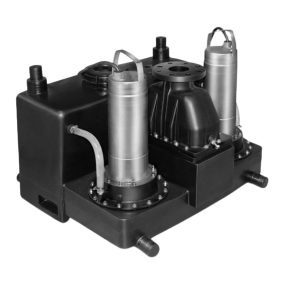
Betriebszeit 12 s / Stillstandzeit 108 s tallfühlern ausgestattet. Die Wicklungsüberwa- chung wird über das angeschlossene Schaltgerät 3.4.2. Abweichende Betriebsart angezeigt und zurückgesetzt. In Abhängigkeit von der Fördermenge kann die Betriebsart zwischen S3 10%/120 s und Der Adapterring verbindet die komplette Einheit S3 20%/120 s variieren. Genauere Angaben mit dem Sammelbehälter. WILO SE 01/2014 Ed.05 DIN A4...
Neu gelieferte Hebeanlagen sind so aufbereitet, dass diese mind. 1 Jahr gelagert werden können. • Einbau- und Betriebsanleitung für die Hebeanlage Bei Zwischenlagerungen muss die Hebeanlage vor • Einbau- und Betriebsanleitung für das Schaltgerät Einbau- und Betriebsanleitung Wilo-RexaLift FIT L...
Inbetriebnahme die Wartungsarbeiten laut EN 12056‑4 durchgeführt werden. 5.2. Aufstellungsarten Wenn Sie diese Regeln beachten, kann Ihre Hebeanlage über einen längeren Zeitraum • Stationäre Trockenaufstellung in Gebäuden und eingelagert werden. Beachten Sie aber, dass die Schächten Elastomerteile einer natürlichen Versprödung WILO SE 01/2014 Ed.05 DIN A4...
Diese müssen am Behälter ein Pumpensumpf angeordnet werden. Die- befestigt werden. Es dürfen nur bautechnisch ser muss eine Mindestabmessung von zugelassene Anschlagmittel verwendet werden. 500x500x500 mm haben. Die verwendete Beachten Sie ebenfalls alle Vorschriften, Regeln Pumpe muss entsprechend der Förderhöhe der Einbau- und Betriebsanleitung Wilo-RexaLift FIT L...
Seite 18
Hierbei ist darauf zu achten, Befestigungsmaterial bohren. dass zwischen Druckleitung und Stutzenende des Flanschstutzens ein min. Abstand von 40...60 mm Dämmstreifen an der Unterseite der Hebeanlage eingehalten wird. anbringen. Hebeanlage erneut positionieren, Montage- winkel einlegen und mit dem entsprechenden Befestigungsmaterial befestigen. WILO SE 01/2014 Ed.05 DIN A4...
Seite 19
• Auf einen sauberen Spanabhub achten: dem Behälterdach (als Kombianschluss DN 50/ • Lässt der Spanabhub nach, erwärmt sich das DN 70). Material zu schnell und schmilzt. Bohrvorgang abbrechen, Material abkühlen Bei Verwendung des DN 50‑Anschlusses sind lassen und Lochsäge reinigen! folgende Punkte zu beachten: Einbau- und Betriebsanleitung Wilo-RexaLift FIT L...
• Für eine sichere und zuverlässige Funktion beach- • Für Hebeanlagen mit CEE M16‑Stecker 16 A ten Sie auch die Einbau- und Betriebsanleitung • Für Hebeanlagen mit CEE M32‑Stecker 25 A der Handmembranpumpe. 5.4.2. Netzanschluss Die Hebeanlage ist mit einem CEE-Stecker ausge- stattet. Für den Anschluss an das Stromnetz muss eine CEE‑Steckdose (nach VDE 0623 bzw. nach WILO SE 01/2014 Ed.05 DIN A4...
Hebeanlage zu vermeiden, sind folgende Punkte unbedingt zu beachten: Die Anlüftschraube muss für einen sicheren An- lagenbetrieb min. 25 mm herausgedreht werden. • Elektrotechnische und mechanische Einstellun- gen sowie die Inbetriebnahme der Hebeanlage Prüfen Sie die Lage der Anlüftschraube. Einbau- und Betriebsanleitung Wilo-RexaLift FIT L...
Sie Druckschläge durch Einstellen der führen und ist strikt untersagt! Pumpenlaufzeit oder bauen Sie gegebenen- falls einen zusätzlichen Rückflussverhinderer 6.5.2. Erstinbetriebnahme mit Gegengewicht ein. Bevor die Hebeanlage in Betrieb genommen werden kann, muss diese befüllt und ein Testlauf WILO SE 01/2014 Ed.05 DIN A4...
6.6.3. Ausfall der Hebeanlage Um den manuellen Betrieb zu beenden, lassen Sie den Taster wieder los. Die Anlage läuft wieder im Sollte die Hebeanlage komplett ausfallen, kann Automatikbetrieb. das Abwasser im Sammelbehälter über die Hand- Einbau- und Betriebsanleitung Wilo-RexaLift FIT L...
Weiterhin muss die Verpackung die Hebeanlage vor Beschädigungen während des Transports schützen. Bei Fragen wenden Sie sich bitte an den Hersteller! Beachten Sie für die Rücklieferung und Einla- gerung ebenfalls das Kapitel „Transport und Lagerung“! WILO SE 01/2014 Ed.05 DIN A4...
• Sichern Sie die Hebeanlage immer gegen unbeab- sichtigtes Wiederanlaufen, indem Sie diese vom • ⇒ Wilo‑Kundendienst Stromnetz wegschalten. Treffen Sie geeignete 13. Radiallager im Motor defekt Vorsichtsmaßnahmen. • ⇒ Wilo‑Kundendienst • Beachten Sie auch die Betriebsanleitungen des 14. Anlagenbedingte Schwingungen verwendeten Zubehörs! Einbau- und Betriebsanleitung Wilo-RexaLift FIT L...
20...25 m³/h S3 15%/120 s S3 15%/120 s S3 15%/120 s S3 15%/120 s S3 15%/120 s 25...40 m³/h S3 10%/120 s S3 15%/120 s S3 10%/120 s S3 15%/120 s S3 10%/120 s WILO SE 01/2014 Ed.05 DIN A4...
< 70 dB(A) Gewicht: 45 kg 47 kg 47 kg 53 kg 53 kg • Der Schalldruckpegel ist vom Betriebspunkt abhängig und kann variieren. Eine unsachgemäße Installation oder ein unzulässiger Betrieb kann den Schalldruckpegel erhöhen. Einbau- und Betriebsanleitung Wilo-RexaLift FIT L...
81 kg 81 kg • Nennstrom pro Pumpe; Im Notbetrieb bei Parallelschaltung der Pumpen verdoppelt sich der Wert • 30 Schaltungen pro Pumpe im Wechselbetrieb • Der Schalldruckpegel ist vom Betriebspunkt abhängig und kann variieren. Eine unsachgemäße Installation oder ein unzulässiger Betrieb kann den Schalldruckpegel erhöhen. WILO SE 01/2014 Ed.05 DIN A4...
Checking the installation/system 6.2. Operation 6.3. Rotation control 6.4. Level control 6.5. Operation 6.6. Emergency operation Decommissioning/disposal 7.1. Switching off the unit 7.2. Removal 7.3. Return delivery / storage 7.4. Disposal Maintenance and repair Installation and operating instructions Wilo-RexaLift FIT L...
Contractual agreements have the • Incorrect storage and transport highest priority and are not superseded by the • Improper assembly/dismantling information in this section. • Insufficient maintenance • Incorrect repairs • Inadequate construction site or construction work WILO SE 01/2014 Ed.05 DIN A4...
These instructions must be strictly observed. Non-observance can result in injury or substan- Instruction symbol, for example, wear protec- tial material damage. tive clothing Installation and operating instructions Wilo-RexaLift FIT L...
Personnel must be informed about the installed systems and how they work. 3. Product description The lifting unit has been manufactured with great care and is subject to constant quality controls. WILO SE 01/2014 Ed.05 DIN A4...
3.2. Set-up • Slaughterhouse waste, disposal of slaughtered The Wilo-RexaLift FIT L is a submersible, fully animals and animal waste (liquid manure, etc.) automatic sewage lifting unit that is ready for connection in single-pump and double-pump •...
Number of poles el then the pump is switched on by the integrated level control and the collected sewage is pumped Mains connection version into the connected pressure pipe. M = 1~ T = 3~ WILO SE 01/2014 Ed.05 DIN A4...
Otherwise, there against kinking, damage and moisture ingress. is a risk of fatal injury! Wear the necessary Furthermore, mounted plugs and switchgear physical protection equipment! must also be protected against moisture ingress. Installation and operating instructions Wilo-RexaLift FIT L...
(such as • The work must be carried out by specialist per- those of the German Association for Water, sonnel, and electrical work must be performed by Wastewater and Waste). an electrician. WILO SE 01/2014 Ed.05 DIN A4...
• Connect the emergency drain • Rough solid material must be removed. • The sump must be decontaminated if neces- sary. • For safety reasons, make sure a second person is present at all times. Installation and operating instructions Wilo-RexaLift FIT L...
Seite 38
(a non-return valve with a • Pipe clamps are allowed to be tightened to a max. tightening torque of 5 Nm. ventilation device is integrated in the pressure connection). The pressure pipe is then mounted on this using flange connectors. WILO SE 01/2014 Ed.05 DIN A4...
Seite 39
• The connection as well as all unions must be For this purpose, the diaphragm hand pump can absolutely leak-tight. be permanently connected to the lifting unit. • A max. tightening torque of 5 Nm is permitted when using pipe clamps. Installation and operating instructions Wilo-RexaLift FIT L...
The back-up fuse required must be rated accord- any defects detected must be repaired! ing to the starting current. Refer to the rating plate for the starting current. WILO SE 01/2014 Ed.05 DIN A4...
3 min • Ambient temperature: 3...40 °C 6.1.2. Checking the system • Operating mode: S3 10 %, 120 s Complete the following tasks before commis- • Fluid is present. sioning: Dry running can lead to damage to the motor, and is strictly prohibited! Installation and operating instructions Wilo-RexaLift FIT L...
Manual operation is not allowed to continue for more than 12 seconds. After that, there must be The pump run-time should be determined as 108 seconds without operation! follows: WILO SE 01/2014 Ed.05 DIN A4...
Open the non-return valve using the ventilation • All work must be carried out with the greatest device in order to drain the pressure pipe into the care. reservoir. • Proper protective clothing is to be worn. Installation and operating instructions Wilo-RexaLift FIT L...
We recommend concluding a maintenance the lifting unit if it is installed. contract for regular maintenance work. Please Once all connections have been disconnected, contact Wilo customer service for more infor- release the anchoring points of the lifting unit in mation about this. the floor 10.
Wilo customer service. 10. Appendix 10.1. Spare parts Spare parts can be ordered from Wilo customer service. To avoid return queries and incorrect orders, the serial and/or article number must always be supplied. Subject to change without prior notice 10.2.
Weight: 45 kg 47 kg 47 kg 53 kg 53 kg • The sound-pressure level depends on the duty point and may vary. Incorrect installation or impermissible opera- tion can increase the sound-pressure level. WILO SE 01/2014 Ed.05 DIN A4...
• Rated current per pump; the value doubles during emergency operation when the pumps are in parallel connection • 30 switches per pump in alternating operation • The sound-pressure level depends on the duty point and may vary. Incorrect installation or impermissible opera- tion can increase the sound-pressure level. Installation and operating instructions Wilo-RexaLift FIT L...
Contrôle du sens de rotation 6.4. Pilotage du niveau 6.5. Fonctionnement 6.6. Régime de secours Mise hors service/Élimination 7.1. Arrêt de l'installation 7.2. Démontage 7.3. Renvoi de livraison/Stockage 7.4. Elimination Maintenance Notice de montage et de mise en service Wilo-RexaLift FIT L...
Le fabricant se garde le droit de faire envoyer par à des modifications techniques au niveau des l'exploitant la station de relevage endommagée à installations et/ou des pièces de montage. Cette l'atelier pour l'examiner. notice de service et de maintenance se rapporte WILO SE 01/2014 Ed.05 DIN A4...
• Attention (consigne sans symbole) autorités légales. Risque d'importants dommages matériels ou de • Les accessoires d’élingage doivent être adaptés destruction totale ! aux conditions en présence (conditions atmos- Notice de montage et de mise en service Wilo-RexaLift FIT L...
Si la station de relevage a été mise à l'arrêt par cours de service. un dispositif de sécurité, attendre l'élimination de la panne avant toute remise en service. WILO SE 01/2014 Ed.05 DIN A4...
Le transport de fluides explosifs (p. ex. de suivantes : l'essence, du kérosène, etc.) est strictement • Arrivée max/h : interdit. Les stations de relevage ne sont pas • Installation à pompe simple : 1050 l conçues pour ces fluides ! • Installation à pompe double : 3000 l Notice de montage et de mise en service Wilo-RexaLift FIT L...
3.2. Structure 3.2.3. Pilotage du niveau La Wilo-RexaLift FIT L est une station de relevage Le pilotage du niveau est monté dans le réservoir collecteur. Des interrupteurs à flotteur au niveau pour eaux chargées immergée, prête à être branchée et entièrement automatique, à pompe de la tringlerie sont utilisés pour servir de cap-...
Classe d'efficacité IE, p. ex. : 1 = IE1 (sur le • Coffret d'alarme modèle de la norme CEI 60034‑30) • Accumulateur (NiMH, 9 V/200 mAh) • Klaxon 230 V, 50 Hz Sans homologation Ex • Voyant lumineux à flash 230 V, 50 Hz Nombre de pôles • Témoin lumineux 230 V, 50 Hz Exécution de l'alimentation réseau M = 1~ T = 3~ Notice de montage et de mise en service Wilo-RexaLift FIT L...
• Placer la station de relevage sur un support fixe et détériorations pendant le transport. Pour toute la protéger contre les chutes et les glissements. question, adressez-vous au fabricant. Les stations de relevage sont stockées horizon- talement. WILO SE 01/2014 Ed.05 DIN A4...
• Hauteur d'arrivée max. : 5 m • Le coffret de commande/la fiche ne sont pas • Pression max. admissible dans la conduite de protégés contre la submersion. S'assurer que le refoulement : 3 bar montage est approprié. Notice de montage et de mise en service Wilo-RexaLift FIT L...
Seite 58
5.3.1. Remarques générales pour la fixation de la sta- tion de relevage Les stations de relevage doivent être montées de manière à être protégées contre la torsion et, se- WILO SE 01/2014 Ed.05 DIN A4...
Seite 59
Poser l'arrivée jusqu'à la cuve et marquer le rac- La conduite de refoulement doit être montée sur cordement de l'arrivée sur la cuve. la vanne d'arrêt avec un manchon à bride, de ma- nière à rester flexible et isolée sur le plan acous- Notice de montage et de mise en service Wilo-RexaLift FIT L...
Seite 60
à membrane manuelle. Pour ce faire, il est possible de raccorder fixement Fig. 6.: Montage de la conduite de purge DN 70 une pompe à membrane manuelle à la station de Raccord combiné 2 Scie relevage. DN 50/70 WILO SE 01/2014 Ed.05 DIN A4...
être protégés contre la submersion. • L'alimentation coté réseau doit posséder un champ magnétique tournant à droite. Notice de montage et de mise en service Wilo-RexaLift FIT L...
• Alimentation avec vanne d'arrêt de montage et de mise en service du coffret de • Tuyau de refoulement avec vanne d'arrêt commande monté. • Purge par le toit • Raccordement électrique : • Champ magnétique tournant à droite. WILO SE 01/2014 Ed.05 DIN A4...
Fermer la vanne d'arrêt dans l'arrivée. La station le réglage de la temporisation des pompes s'ef- de relevage ne doit normalement plus se mettre fectue en réglant le potentiomètre dans le coffret en route car plus aucun fluide ne s'écoule. de commande. Notice de montage et de mise en service Wilo-RexaLift FIT L...
Fermer la vanne d'arrêt de la conduite de refou- lement. Pomper le fluide avec la pompe à membrane manuelle hors du réservoir collecteur dans la conduite de refoulement. Pour ce faire, respecter la notice de montage et de mise en service de la pompe à membrane manuelle. WILO SE 01/2014 Ed.05 DIN A4...
• Evacuer l'eau de rinçage aux endroits appro- locales. priés de la canalisation. 7.4.2. Produit Une élimination réglementaire de ce produit préviendra toute pollution de l'environnement et toute atteinte à la santé. Notice de montage et de mise en service Wilo-RexaLift FIT L...
Sens de rotation erroné est toujours réservée au service après-vente Wilo. • Echanger 2 phases du câble d'alimentation ⇒ Les intervalles d'entretien des stations de rele- service après-vente Wilo vage s'appuient sur la norme EN 12056‑4 :...
S3 15%/120 s S3 15%/120 s S3 15%/120 s S3 15%/120 s 25...40 m³/h S3 10%/120 s S3 15%/120 s S3 10%/120 s S3 15%/120 s S3 10%/120 s Notice de montage et de mise en service Wilo-RexaLift FIT L...
Seite 68
945 mm 945 mm 945 mm Niveau de pression acous- < 70 dB(A) < 70 dB(A) < 70 dB(A) < 70 dB(A) < 70 dB(A) tique : Poids : 45 kg 47 kg 47 kg 53 kg 53 kg WILO SE 01/2014 Ed.05 DIN A4...
Seite 69
Niveau de pression acous- < 70 dB(A) < 70 dB(A) < 70 dB(A) < 70 dB(A) < 70 dB(A) tique : Poids : 65 kg 69 kg 69 kg 81 kg 81 kg Notice de montage et de mise en service Wilo-RexaLift FIT L...
Seite 71
Control del sentido de giro 6.4. Control de nivel 6.5. Funcionamiento 6.6. Modo operativo de emergencia Puesta fuera de servicio/Eliminación 7.1. Desconexión de la instalación 7.2. Desmontaje 7.3. Devolución/almacenamiento 7.4. Eliminación Mantenimiento Instrucciones de instalación y funcionamiento Wilo-RexaLift FIT L...
Este manual de servicio y manteni- reserva el derecho de solicitar el envío a la fábrica miento se refiere al sistema de elevación de aguas del sistema de elevación de aguas defectuoso por indicado en la portada. parte del titular para su inspección. WILO SE 01/2014 Ed.05 DIN A4...
• Por lo general solo se deben utilizar medios de fijación que estén homologados legalmente como • Las indicaciones de seguridad que hacen referen- tales cia a daños personales aparecen en color negro y Instrucciones de instalación y funcionamiento Wilo-RexaLift FIT L...
En función de varios factores (p. ej., instalación, fijación de los accesorios y las tuberías, punto de Para la conexión se debe observar el capítulo “Co- nexión eléctrica”. Las especificaciones técnicas trabajo, etc.) durante el funcionamiento, la pre- sión acústica incluso puede ser mayor. se deben respetar rigurosamente. Los sistemas de elevación de aguas deben conectarse a tierra. WILO SE 01/2014 Ed.05 DIN A4...
El caudal de afluencia máximo posible debe no, etc.). ¡Los sistemas de elevación de aguas ser siempre inferior al caudal de la bomba en no están diseñados para transportar estos el punto de trabajo correspondiente. medios! Instrucciones de instalación y funcionamiento Wilo-RexaLift FIT L...
3.2. Estructura 3.2.3. Control de nivel Wilo-RexaLift FIT L es un sistema de elevación El control de nivel está montado en el depósito de aguas fecales inundable, listo para la conexión colector. A modo de sondas se emplean inte- y completamente automático en ejecución de...
• Piloto de indicación 230 V, 50 Hz Número de polos Ejecución de la alimentación eléctrica M = 1~ T = 3~ 0026 /10 = potencia nominal del motor P en kW Frecuencia 5 = 50 Hz 6 = 60 Hz Instrucciones de instalación y funcionamiento Wilo-RexaLift FIT L...
Las piezas se deben cerrar herméticamente en manera estable sobre una base firme y asegu- sacos de plástico suficientemente grandes y re- rarlo para que no pueda caerse o resbalarse. Los sistentes a la rotura y se deben embalar de forma segura para su expedición. Además, el embalaje WILO SE 01/2014 Ed.05 DIN A4...
Los siguientes límites de uso se deben respe- blema. Nunca se debe transportar el sistema de tar rigurosamente. elevación de aguas tirando del cable de entrada de corriente. Compruebe si la longitud de cable Instrucciones de instalación y funcionamiento Wilo-RexaLift FIT L...
Seite 80
Coloque de nuevo el sistema de elevación de reglamentos, las normas y las leyes válidas para aguas, introduzca los codos de montaje y fíjelo trabajar con cargas pesadas y debajo de cargas con el material de fijación correspondiente. suspendidas. Lleve el equipo de protección personal adecuado. WILO SE 01/2014 Ed.05 DIN A4...
Seite 81
Para una entrada DN 150 se debe contar con el de corte mediante una tubuladora con brida de forma flexible y con aislamiento acústico. Debe kit de entrada DN 150 (disponible como acce- tenerse en cuenta que entre la tubería de impul- sorio). Instrucciones de instalación y funcionamiento Wilo-RexaLift FIT L...
Seite 82
Desbarbe y pula la abertura. recomendamos instalar de forma fija la bomba Pase el manguito adjunto (DN 70) hasta la unión manual de membrana al sistema de elevación interior por el manguito y fíjelo con la abrazadera de aguas. de tubo. Coloque el tubo de ventilación en el manguito. WILO SE 01/2014 Ed.05 DIN A4...
Como fusibles de línea solo se pueden utilizar fu- sibles de acción lenta o fusibles automáticos con Instrucciones de instalación y funcionamiento Wilo-RexaLift FIT L...
• Se cuenta con un campo giratorio con el senti- do de giro a la derecha. • El sistema de elevación de aguas está asegura- do y puesto a tierra según las normativas. • Montaje del conmutador WILO SE 01/2014 Ed.05 DIN A4...
Cierre la llave de corte de la entrada. Normalmen- te el sistema de elevación de aguas no se puede conectar, puesto que ya no fluye ningún fluido. Sin embargo, si a pesar de todo el sistema de elevación de aguas se conecta, es indicio de Instrucciones de instalación y funcionamiento Wilo-RexaLift FIT L...
Cierre la llave de corte de la tubería de impulsión. Bombee el fluido desde el depósito colector hasta la tubería de impulsión con la bomba manual de membrana. Observe las Instrucciones de insta- lación y funcionamiento de la bomba manual de membrana. WILO SE 01/2014 Ed.05 DIN A4...
• ¡La ropa protectora y los trapos deben ta eliminación en las oficinas municipales, en desecharse conforme al código de residuos un punto limpio o allí donde haya adquirido el TA 524 02 y la Directiva de la CE 91/689/CEE o producto. conforme a las directivas locales! Instrucciones de instalación y funcionamiento Wilo-RexaLift FIT L...
16. Ventilación de la bomba obstruida Altura de impulsión 1, 2, 3, 4, 5, 8, 11, 12, 13, 16 insuficiente • Limpiar la tubería de ventilación de la bomba ⇒ servicio técnico de Wilo 17. Disparo de la protección de motor electrónica WILO SE 01/2014 Ed.05 DIN A4...
S3 15%/120 s S3 15%/120 s S3 15%/120 s S3 15%/120 s S3 15%/120 s 25...40 m³/h S3 10%/120 s S3 15%/120 s S3 10%/120 s S3 15%/120 s S3 10%/120 s Instrucciones de instalación y funcionamiento Wilo-RexaLift FIT L...
Seite 90
945 mm 945 mm 945 mm Nivel sonoro: < 70 dB(A) < 70 dB(A) < 70 dB(A) < 70 dB(A) < 70 dB(A) Peso: 45 kg 47 kg 47 kg 53 kg 53 kg WILO SE 01/2014 Ed.05 DIN A4...
Seite 91
1060 mm 1060 mm Nivel sonoro: < 70 dB(A) < 70 dB(A) < 70 dB(A) < 70 dB(A) < 70 dB(A) Peso: 65 kg 69 kg 69 kg 81 kg 81 kg Instrucciones de instalación y funcionamiento Wilo-RexaLift FIT L...
Seite 93
Comando 6.3. Controllo del senso di rotazione 6.4. Controllo livello 6.5. Funzionamento 6.6. Funzionamento di emergenza Messa a riposo/smaltimento 7.1. Spegnimento dell'impianto 7.2. Smontaggio 7.3. Spedizione di ritorno/immagazzinaggio 7.4. Smaltimento Manutenzione Istruzioni di montaggio, uso e manutenzione Wilo-RexaLift FIT L...
Il presente manuale di eserci- I danni alla stazione di sollevamento sono esclusi zio e manutenzione fa riferimento alla stazione di da garanzia o responsabilità qualora valgano uno sollevamento indicata sul frontespizio. o più punti seguenti: WILO SE 01/2014 Ed.05 DIN A4...
Come simboli di sicurezza vengono utilizzati sim- • Nell'utilizzare attrezzature di lavoro mobili per il boli di pericolo, divieto oppure obbligo. sollevamento di carichi provvedere a garantirne la Esempio: stabilità durante l'impiego. Istruzioni di montaggio, uso e manutenzione Wilo-RexaLift FIT L...
Se si allaccia la stazione di sollevamento alla rete rispettivo punto di lavoro e a tutte le condizioni di elettrica locale, per soddisfare i requisiti di com- esercizio. WILO SE 01/2014 Ed.05 DIN A4...
La stazione di sollevamento serve al drenaggio • Altezza di ingresso max.: 5 m antiriflusso da punti di scarico in edifici e aree • Pressione max. nel tubo di mandata: 3 bar aperte al di sotto del livello di riflusso e si presta, • Temperatura max. del fluido: 40 °C, 60 °C per max. conformemente alla norma EN 12050‑1, al pom- 3 min Istruzioni di montaggio, uso e manutenzione Wilo-RexaLift FIT L...
3.2.3. Controllo livello 3.2. Struttura Il controllo livello è integrato nel serbatoio di raccolta. Come sensori vengono impiegati inter- La Wilo-RexaLift FIT L è una stazione di solleva- ruttori a galleggiante su barre sospese. I punti mento per acque cariche sommergibile, pronta per il collegamento e completamente automatica d'intervento sono qui fissi.
• Stazione di sollevamento per acque cariche mento della spedizione l'azienda di trasporti o pronta per il collegamento con apparecchio di il produttore, in quanto successivamente non è comando, cavo da 4 m e spina più possibile presentare reclami. Eventuali danni Istruzioni di montaggio, uso e manutenzione Wilo-RexaLift FIT L...
• In caso di installazione della stazione di solleva- mento in un pozzetto osservare i punti seguenti: Istruzioni di montaggio, uso e manutenzione Wilo-RexaLift FIT L...
Seite 102
• Nel tubo di mandata non è consentita la riduzio- • La profondità del foro dipende dalla lunghezza ne del diametro. delle viti. Consigliamo una profondità del foro pari alla lunghezza della vite +5 mm. WILO SE 01/2014 Ed.05 DIN A4...
Seite 103
2 Attacco diretto WC a pavimento • Ridurre il numero di giri del trapano. 3 Attacco diretto WC a parete • La pressione di avanzamento può variare men- tre è in corso la trapanatura. Istruzioni di montaggio, uso e manutenzione Wilo-RexaLift FIT L...
Seite 104
Dal momento che ciò non è sempre Osservare i seguenti punti: possibile, la RexaLift FIT L è dotata di un attac- • La pompa a membrana ad azionamento manuale co supplementare DN 50 sul tetto del serbatoio deve essere installata a un'altezza adeguata a un (come attacco combinato DN 50/DN 70).
è riportata sulla targhetta sollevamento. dati pompa. Devono essere assolutamente osservate e verifi- Come fusibile possono essere utilizzati solo cate le condizioni secondarie seguenti: fusibili ad azione ritardata o interruttori automa- • Modo di funzionamento • Alimentazione max./h Istruzioni di montaggio, uso e manutenzione Wilo-RexaLift FIT L...
6.5. Funzionamento esterna (opzionale) 6.5.1. Condizioni di esercizio • Installazione della pompa a membrana ad aziona- mento manuale per lo scarico di emergenza La stazione di sollevamento può essere azionata solo alle condizioni seguenti: WILO SE 01/2014 Ed.05 DIN A4...
Di regola, la stazione di sollevamento opera nel Riaprire la valvola d'intercettazione nell'alimen- funzionamento automatico e viene accesa e tazione per consentire l'afflusso del fluido! spenta mediante il controllo livello integrato. Istruzioni di montaggio, uso e manutenzione Wilo-RexaLift FIT L...
è possibile procedere ai lavori. Senza fognario! tali controlli sussiste pericolo di morte! • Smaltire gli indumenti protettivi e gli stracci in base al codice di identificazione dei rifiuti TA 524 02 e la direttiva CE 91/689/CEE o le direttive locali! WILO SE 01/2014 Ed.05 DIN A4...
Su tutti gli interventi di manutenzione e ripara- Allentare l'attacco della pompa a membrana ad zione deve essere redatto un protocollo, firmato azionamento manuale, se presente, sulla stazione a sua volta dall'addetto del servizio assistenza e dall'utente. di sollevamento. Istruzioni di montaggio, uso e manutenzione Wilo-RexaLift FIT L...
10.1. Parti di ricambio Funzionamento a due fasi Le ordinazioni delle parti di ricambio avvengono • Sostituire il fusibile difettoso ⇒ elettricista attraverso il Servizio Assistenza Clienti Wilo. Al fine di evitare richieste di chiarimenti o ordina- • Verificare i collegamenti elettrici ⇒ elettricista zioni errate, indicare sempre il numero di serie/ Il motore non si avvia perché manca tensione dell'articolo.
S3 15%/120 s S3 15%/120 s S3 15%/120 s S3 15%/120 s S3 15%/120 s 25...40 m³/h S3 10%/120 s S3 15%/120 s S3 10%/120 s S3 15%/120 s S3 10%/120 s Istruzioni di montaggio, uso e manutenzione Wilo-RexaLift FIT L...
47 kg 53 kg 53 kg • Il livello di pressione acustica dipende dal punto di lavoro e può variare. Un'installazione non a regola d'arte o un funzionamento non ammesso può aumentare il livello di pressione acustica. WILO SE 01/2014 Ed.05 DIN A4...
• Il livello di pressione acustica dipende dal punto di lavoro e può variare. Un'installazione non a regola d'arte o un funzionamento non ammesso può aumentare il livello di pressione acustica. Istruzioni di montaggio, uso e manutenzione Wilo-RexaLift FIT L...
Seite 115
6.3. Controlo do sentido de rotação 6.4. Controlo do nível 6.5. Funcionamento 6.6. Funcionamento de emergência Colocação fora de funcionamento/ Eliminação 7.1. Desligar o equipamento 7.2. Desmontagem 7.3. Devolução/Armazenamento 7.4. Eliminação Conservação Manual de Instalação e funcionamento Wilo-RexaLift FIT L...
Para a implementação de alterações técnicas nos equipamentos e/ou nos componentes, o fabri- cante reserva-se todos os direitos. Este manual de instruções e de manutenção refere-se à esta- ção elevatória indicada na folha de rosto. WILO SE 01/2014 Ed.05 DIN A4...
às respetivas condições (clima, dispositivo de • As indicações de segurança que alertam para da- nos pessoais são apresentadas a preto e possuem engate, carga, etc.) e guardados com cuidado. sempre um símbolo de segurança. Como símbolos Manual de Instalação e funcionamento Wilo-RexaLift FIT L...
Se a estação elevatória tiver sido desligada por um órgão de proteção, esta só pode ser nova- mente ligada após a eliminação da falha. WILO SE 01/2014 Ed.05 DIN A4...
• Pressão máx. permitida na tubagem de pressão: e, de acordo com a EN 12050‑1, adequa-se ao 3 bar transporte de águas residuais (com/sem maté- • Temperatura máx. dos líquidos: 40 °C, 60 °C para ria fecal) da área doméstica segundo a norma um máximo de 3 min EN 12056‑1. • Temperatura ambiente máx.: 40 °C • Modo de funcionamento: S3 10 %, 120 s Manual de Instalação e funcionamento Wilo-RexaLift FIT L...
3.2. Estrutura letor. Como transmissores de sinais, são utilizados interruptores de boia de tirante. Neste caso, os A Wilo-RexaLift FIT L é uma estação elevató- pontos de comutação estão predefinidos. ria para água residual submersível, pronta para conexão e totalmente automática na versão de sistema de bomba simples e bomba dupla.
P/MS = com ficha e aparelho de distribuição 4.1. Fornecimento Após a entrada da mercadoria, esta deve ser ime- diatamente verificada quanto a danos e quanto à sua plenitude. Em caso de eventuais falhas, logo no dia de recebimento, é necessário entrar em Manual de Instalação e funcionamento Wilo-RexaLift FIT L...
5.1. Informação geral • Todos os cabos elétricos devem ser protegidos Para o planeamento e o funcionamento de siste- contra dobras, danos e penetração de humidade. mas relacionados com a tecnologia de águas re- WILO SE 01/2014 Ed.05 DIN A4...
• Na instalação da estação elevatória num poço, qualquer homologação de proteção contra devem ser respeitados adicionalmente os seguin- explosão! tes pontos: • Tome as medidas necessárias para evitar uma atmosfera explosiva na área de operação! Manual de Instalação e funcionamento Wilo-RexaLift FIT L...
Seite 124
Ao ligar a tubagem de pressão, é necessário res- mento do parafuso +5 mm. peitar o seguinte: • O pó produzido durante a perfuração prejudica • A tubagem de pressão tem de ser auto-portante. a força de retenção. Por isso: Soprar ou aspirar sempre o furo. WILO SE 01/2014 Ed.05 DIN A4...
Seite 125
Unte a parte interior do vedante de entrada com Se a entrada ocorrer fora das áreas marcadas, é um lubrificante possível Coloque a braçadeira para tubos no vedante de • que o equipamento fique com fugas. entrada. Manual de Instalação e funcionamento Wilo-RexaLift FIT L...
Seite 126
• Para um funcionamento perfeito e seguro, res- de entrada da estação elevatória. Como isso nem peite também o manual de instalação e funciona- sempre é possível, a RexaLift FIT L está equipada mento da bomba manual de membrana. com uma ligação adicional de DN 50 no topo do tanque (como ligação combinada DN 50/DN 70).
Se existir perigo de formação de gases tóxicos, tem de ser O aparelho de distribuição está equipado de fá- garantida uma ventilação suficiente. brica com um besouro. Adicionalmente, é possível Manual de Instalação e funcionamento Wilo-RexaLift FIT L...
Abra a tampa de inspeção. Verifique se o interruptor de boia se move facil- mente e se está bem assente no tirante. Volte a fechar a abertura de inspeção. WILO SE 01/2014 Ed.05 DIN A4...
• Se, antes de a bomba se desligar, ocorrer um ruído Solte o botão para terminar o funcionamento ma- de esvaziamento (transporte de uma mistura de nual. O equipamento volta ao modo automático. água e ar), mas o dispositivo de afluxo fechar de Manual de Instalação e funcionamento Wilo-RexaLift FIT L...
Se o controlo do nível se avariar, o tanque coletor Agora, é possível iniciar os trabalhos de desmon- pode ser esvaziado no funcionamento manual. tagem, manutenção e armazenamento. Pode encontrar informações a este respeito no ponto “Funcionamento manual”. WILO SE 01/2014 Ed.05 DIN A4...
• Respeite igualmente o manual de instalação e bém o capítulo “Transporte e armazenamento”! funcionamento dos acessórios usados! • As alterações arbitrárias na estação elevatória são realizadas por conta e risco do cliente e isentam o Manual de Instalação e funcionamento Wilo-RexaLift FIT L...
Funcionamento em duas fases A encomenda de peças de substituição é feita • Substituir o fusível avariado ⇒ eletricista através do serviço de assistência a clientes Wilo. Para evitar questões e encomendas erradas, deve • Verificar a ligação elétrica ⇒ eletricista indicar sempre o número de série e/ou o número O motor não arranca devido à...
S3 15%/120 s S3 15%/120 s S3 15%/120 s S3 15%/120 s S3 15%/120 s 25...40 m³/h S3 10%/120 s S3 15%/120 s S3 10%/120 s S3 15%/120 s S3 10%/120 s Manual de Instalação e funcionamento Wilo-RexaLift FIT L...
45 kg 47 kg 47 kg 53 kg 53 kg • O nível de pressão acústica depende do ponto de funcionamento e pode variar. Uma instalação incorreta ou um funcionamento não autorizado pode aumentar o nível de pressão acústica. WILO SE 01/2014 Ed.05 DIN A4...
30 conexões por bomba no funcionamento alternado • O nível de pressão acústica depende do ponto de funcionamento e pode variar. Uma instalação incorreta ou um funcionamento não autorizado pode aumentar o nível de pressão acústica. Manual de Instalação e funcionamento Wilo-RexaLift FIT L...
Seite 137
Opstellingswijzen 5.3. Installatie 5.4. Elektrische aansluiting Inbedrijfname 6.1. Controle van de installatie/het systeem 6.2. Bediening 6.3. Draairichtingcontrole 6.4. Niveauregeling 6.5. Bedrijf 6.6. Noodbedrijf Uitbedrijfname/afvoeren 7.1. Installatie uitschakelen 7.2. Demontage 7.3. Terugsturen/opslag 7.4. Afvoeren Onderhoud Inbouw- en bedieningsvoorschriften Wilo-RexaLift FIT L...
Er kan letsel ontstaan! met elektrische toestellen moet ervoor gezorgd worden dat er geen explosiegevaar is. • Voorzichtig (Let op zonder symbool) Er kan aanzienlijke materiële schade ontstaan, een totaal verlies is niet uitgesloten! Inbouw- en bedieningsvoorschriften Wilo-RexaLift FIT L...
Wisselen een lekstroom-veiligheidsschakelaar (RCD) is naar een ander medium is daarom niet mogelijk. vereist. Bij opvoerinstallaties met vrije kabelui- Gebruik in drinkwater is niet toegestaan! teinden moet er voor draaistroommotoren een WILO SE 01/2014 Ed.05 DIN A4...
GEVAAR door explosieve media! Het transporteren van explosieve media (bijv. • Max. toevoerhoogte: 5 m benzine, kerosine enz.) is ten strengste ver- • Max. toegestane druk in persleiding: 3 bar boden. De opvoerinstallaties zijn niet bedoeld • Max. mediumtemperatuur: 40 °C, 60 °C geduren- voor deze media! de max. 3 min Inbouw- en bedieningsvoorschriften Wilo-RexaLift FIT L...
3.2.3. Niveauregeling De niveauregeling is ingebouwd in het verzamel- 3.2. Opbouw reservoir. Als signaalgevers worden stangen-vlot- terschakelaars gebruikt. De schakelpunten zijn De Wilo-RexaLift FIT L is een overstroomba- hierbij vast voorgeschreven. re, stekkerklare en volautomatisch werkende afvalwater-opvoerinstallatie in enkelpomp- en dubbelpompuitvoering.
Bij het gebruik van • 1x manchet voor ontluchtingsaansluiting DN 70 kettingen moeten deze tegen wegglijden worden • 1x flensaansluiting DN 80/100 met vlakke af- geborgd. dichting, manchet, buisklemmen, schroeven en Inbouw- en bedieningsvoorschriften Wilo-RexaLift FIT L...
Met name optredende drukpieken, bijv. bij het sluiten van de terugslagklep, kunnen afhankelijk van de bedrijfsomstandigheden een veelvoud van de pompdruk bedragen. Deze drukpieken kunnen leiden tot vernieling van de installatie. Daarom WILO SE 01/2014 Ed.05 DIN A4...
Bij de inbouw van de opvoerinstallatie dient u op het volgende te letten: • Deze werkzaamheden moeten door vakkundig personeel worden uitgevoerd en elektrische werkzaamheden moeten door een elektrotechni- cus worden uitgevoerd. Inbouw- en bedieningsvoorschriften Wilo-RexaLift FIT L...
Seite 146
Daarom geldt: Boorgat altijd uitblazen of • De persleiding moet trillingsvrij, geluidsgeïsoleerd uitzuigen. en flexibel worden aangesloten. • Let er bij de montage op dat het bevestigingsma- • De aansluiting en alle verbindingen moeten abso- teriaal niet beschadigd raakt. luut dicht zijn. WILO SE 01/2014 Ed.05 DIN A4...
Seite 147
Twee gecombineerde aansluitingen DN 50/DN 70 Door een golfachtige toevoer en het binnen- op het reservoirdak zijn beschikbaar voor het aansluiten van de ontluchtingsleiding. dringen van lucht kunnen er storingen in de werking van de opvoerinstallatie ontstaan! Inbouw- en bedieningsvoorschriften Wilo-RexaLift FIT L...
Seite 148
• Buisklemmen mogen met een maximaal aan- ook direct naar de verzamelleiding worden draaimoment van 5 Nm worden aangedraaid. geleid! Fig. 7.: Montage DN 50-toevoer Combinatie-aansluiting 2 Zaag DN 50/70 Combinatie‑aansluiting DN 50/70 met een pas- sende zaag openen. Daartoe het verbindingsstuk DN 50 boven de verdikking afzagen. Opening ontbramen en gladmaken. WILO SE 01/2014 Ed.05 DIN A4...
Hiervoor moeten de standen van de afzonderlijke de opgegeven bedrijfsomstandigheden. DIP-schakelaars gecontroleerd worden. • Bij werkzaamheden in putten moet altijd een Lees hiervoor de inbouw- en bedieningsvoor- tweede persoon aanwezig zijn. Bij gevaar voor de schriften van de gemonteerde schakelkast! Inbouw- en bedieningsvoorschriften Wilo-RexaLift FIT L...
Functietest van de niveauregeling De niveauregeling moet op een foutloze mecha- nische toestand gecontroleerd worden. Open de revisiedeksel. Controleer de vlotterschakelaar op bewegings- vrijheid en een goede pasvorm op de arm. Sluit de revisieopening opnieuw. WILO SE 01/2014 Ed.05 DIN A4...
De looptijd van de pomp moet als volgt worden bepaald: • Als er een slurpgeluid wordt geproduceerd voor- dat de pomp wordt uitgeschakeld (afgifte van een water-luchtmengsel), maar de terugslagklep stil of slechts licht sluit, moet de looptijd van de Inbouw- en bedieningsvoorschriften Wilo-RexaLift FIT L...
6.6.2. Niveauregeling defect Wanneer de niveauregeling defect is, kan het verzamelreservoir in handmatig bedrijf worden geleegd. Informatie hierover vindt u onder het punt “Handmatig bedrijf”. WILO SE 01/2014 Ed.05 DIN A4...
• Beveilig de opvoerinstallatie altijd tegen het per voerinstallatie beschermen tegen beschadigingen ongeluk inschakelen door deze van het elektrici- tijdens het transport. Neem bij vragen contact op teitsnet te halen. Tref de nodige voorzorgsmaat- met de fabrikant! regelen. Inbouw- en bedieningsvoorschriften Wilo-RexaLift FIT L...
10. Bijlage technicus Motorwikkeling of elektrische leiding defect • Motor en elektrische aansluiting laten contro- 10.1. Reserveonderdelen leren ⇒ Wilo‑servicedienst Deze bestelt u bij de Wilo-servicedienst. Om latere vragen of verkeerde bestellingen te vermij- Terugslagklep verstopt den, moet altijd het serie- en/of artikelnummer • Terugslagklep reinigen ⇒ Wilo‑servicedienst worden aangegeven. Te sterke waterspiegeldaling in het reservoir •...
Geluidsniveau: < 70 dB(A) < 70 dB(A) < 70 dB(A) < 70 dB(A) < 70 dB(A) Gewicht: 45 kg 47 kg 47 kg 53 kg 53 kg • Het geluidsniveau is afhankelijk van het bedrijfspunt en kan variëren. Een ondeskundige installatie of een niet-toegestaan bedrijf kan het geluidsniveau verhogen. Inbouw- en bedieningsvoorschriften Wilo-RexaLift FIT L...
69 kg 81 kg 81 kg • Nominale stroom per pomp; In noodbedrijf met parallel schakelen van de pompen verdubbelt de waarde • 30 schakelingen per pomp in wisselbedrijf • Het geluidsniveau is afhankelijk van het bedrijfspunt en kan variëren. Een ondeskundige installatie of een niet-toegestaan bedrijf kan het geluidsniveau verhogen. WILO SE 01/2014 Ed.05 DIN A4...
Seite 157
Saklama 4.4. Geri gönderme Kurulum 5.1. Genel 5.2. Kurulum türleri 5.3. Montaj 5.4. Elektrik bağlantısı İşletime alma 6.1. Kurulumun/tesisin kontrolü 6.2. Kumanda 6.3. Dönüş yönü kontrolü 6.4. Seviye kumandası 6.5. İşletim 6.6. Acil işletim İşletimden çıkarma/bertaraf 7.1. Tesisin kapatılması 7.2. Sökme 7.3. Geri gönderme/saklama 7.4. Bertaraf Revizyon Montaj ve kullanma kılavuzu Wilo‑RexaLift FIT L...
Bu bölüm, garanti ile ilgili genel bilgileri içermek- • Belirlenen amacın dışında kullanılması tedir. Sözleşmede kararlaştırılan hususlar daima • Düzgün yapılmayan nakliye ve saklama daha yüksek önceliğe sahiptir ve bu bölüm nede- • Kurallara uygun şekilde yapılmayan montaj/sökme niyle geçerliliklerini yitirmemektedir! işlemleri Üretici, aşağıdaki koşullara uyması şartıyla, satmış • Düzgün yapılmayan bakım olduğu terfi tesislerindeki tüm sorunları gider- • Düzgün yapılmayan tamir mekle yükümlüdür. • Sorunlu yapı temeli ve/veya inşaat çalışmaları • Kimyasal, elektro kimyasal veya elektriksel etkiler WILO SE 01/2014 Ed.05 DIN A4...
önlemler alınmalıdır. Örnek: • Asılı yükün altında insanların durmasını önleyecek önlemler alınmalıdır. Ayrıca, asılı yüklerin insan- ların bulunduğu çalışma alanlarının üzerinden Tehlike sembolü: Genel tehlike geçirilmesi de yasaktır. • Mobil yük kaldırma ekipmanları kullanıldığında, gerekiyorsa (örn. görüş engellenmişse), koordi- nasyon için ikinci bir kişi görevlendirilmelidir. Örn. elektrik akımı tehlike sembolü • Kaldırılan yük, elektriğin kesilmesi durumunda kimsenin yaralanmasına yol açmayacak şekilde taşınmalıdır. Ayrıca, hava şartları bozulduğunda açık havada yapılan çalışmalar durdurulmalıdır. Yasak sembolü, örn. ‘Girilmez!’ Bu notlara kat'i olarak uyulmalıdır. Aksi takdirde yaralanmalar ve/veya ağır hasar meydana gele- bilir. Emir sembolü, örn. ‘Vücut koruyucu kullanın’ Montaj ve kullanma kılavuzu Wilo‑RexaLift FIT L...
2.9. CE işareti 2.4. Emniyet ve kontrol düzenekleri CE işareti, toplama haznesine takılı olan isim plakasında yer alır. Motor, bir termik bobin kontrolüne sahiptir. İşle- tim sırasında bu bobinin aşırı ısınması halinde terfi tesisi kapatılır. 3. Ürünün tanımı Kontrol düzeneği, fabrika tarafından kumanda cihazına bağlanmıştır. Terfi tesisi büyük bir özenle üretilmiştir ve sürekli olarak kalite kontrolü uygulanmaktadır. Kurulum Personel, monte edilmiş olan düzenekler ve bun- ların işlevleri hakkında bilgilendirilmiş olmalıdır. ve bakım doğru yapıldığı takdirde sorunsuz bir çalışma sağlanmış olacaktır. DIKKAT! Bobin kontrolü çıkartılmış, hasarlı ve/veya çalışmaz durumdayken terfi tesisi çalıştırılma- malıdır! WILO SE 01/2014 Ed.05 DIN A4...
• Moloz, kül, çöp, cam, kum, alçı, çimento, kireç, harç, elyaf, kumaş, kağıt mendil, ıslak mendil (örn. • “Teknik veriler” maddesi altında verilen diğer fayans mendili, ıslak tuvalet kağıdı), bebek bezi, bilgilere de dikkat edin! karton, kalın kağıt, sentetik reçine, katran, mutfak atıkları, katı ve sıvı yağlar 3.2. Montaj • Hayvan kesimi, hayvan kadavra imhası ve hayvan- Wilo‑RexaLift FIT L, tek pompalı ve çift pompalı cılık (hayvan gübresi...) atıkları modelde sunulan, tam otomatik çalışan, bağlan- maya hazır ve dalgıç tipi bir atıksa terfi tesisidir. • Ağır metaller, biosidler, bitki koruyucuları, asitler, kostikler, tuzlar, yüzme havuzu suyu gibi zehirli, agresif ve aşındırıcı maddeler Fig. 1.: Tanımı • Fazla köpürmeye yol açan ve aşırı miktarlarda Toplama kabı temizlik, dezenfeksiyon, durulama ve yıkama Revizyon deliği...
/10 = nominal motor gücü P , kW olarak seviye kumandası üzerinden pompa çalıştırılır ve Frekans biriken atıksa bağlı basınç hattına basılır. 5 = 50 Hz Kapanış seviyesine ulaşıldığında, ayarlanan takip 6 = 60 Hz süresi dolduktan sonra pompa kapanır. Ölçüm voltajı kodu Sel suyu seviyesine ulaşılırsa, bir alarm sesi duyu- Ek elektrik donanımı lur ve tüm pompalar kapanmaya zorlanır. Tekrar O = serbest kablo ucu sel seviyesinin altına inildiğinde ise, takip süresi P/MS P = fişli dolduktan sonra pompalar kapatılır ve uyarı iletisi P/MS = Fiş ve kumanda cihazı ile otomatik olarak onaylanır. WILO SE 01/2014 Ed.05 DIN A4...
üreticiye bildirilmelidir, aksi takdirde herhan- terfi tesisi zarar görecektir. Elektrik bileşenle- gi bir hak talep edilemez. Olası sorunlar teslimat rini hiçbir zaman bir sıvıya daldırmayın ve nem belgelerine işlenmelidir. nüfuzuna karşı koruyun. 4.2. Nakliye Nakliye için öngörülen ve izin verilen bağlantı, ta- • Terfi tesisi direkt güneş ışınlarına ve dona karşı şıma ve kaldırma gereçleri kullanılmalıdır. Bunlar, korunmalıdır. Bunlar, toplama haznesinde veya terfi tesisinin tehlikesiz bir şekilde taşınabilmesi elektrik bileşenlerinde ciddi hasara yol açabilir. Montaj ve kullanma kılavuzu Wilo‑RexaLift FIT L...
• EN 12050‑1 ve EN 12056 (bina için ağır güç drenaj tesisleri) • Oda drenajı için odada bir pompa çukuru bu- Bu doğrultuda ülkenizde geçerli olan yerel lunmalıdır. Bu çukur en az 500x500x500 mm direktiflere de uyun (örn. ülkenizdeki inşaat ölçülerinde olmalıdır. Kullanılan pompa, terfi tüzüğü)! tesisinin basma yüksekliğine göre seçilmelidir. Acil durumda pompa çukuru elle boşaltılabilmelidir. 5.2. Kurulum türleri • Akım iletim hatları, her zaman için tehlikesiz bir • Binaların ve kuyuların içine sabit kuru kurulum işletime ve sorunsuz bir montaja/sökme işlemi- ne izin verecek şekilde döşenmelidir. Terfi tesisi hiçbir zaman elektrik iletim hattından taşınmamalı veya çekilmemelidir. Mevcut kablo uzunluğunun WILO SE 01/2014 Ed.05 DIN A4...
Seite 165
çıkılabilir. Bunun sonucunda basınç hattı rektiflere, kurallara ve yasalara da uyun. Gerekli patlayabilir! Basınç piklerini daha basınç hattın vücut koruyucu ekipmanları kullanın. döşerken önlemeye çalışın. Kullanılan boru hatları ve bağlantı elemanları uygun basınç 5.3.1. Terfi tesisinin sabitlenmesine ilişkin temel direncine sahip olmalıdır! bilgiler Terfi tesisleri burulmaya ve ‑ kullanım yerine bağlı olarak ‑ artan basınca dayanıklı bir şekilde monte edilmelidir. Bunun için terfi tesisi odanın zeminine ankrajlanmalıdır. Montaj farklı yapı malzemelerin- de (beton, plastik v.s.) yapılabilir. Bu nedenle, söz Montaj ve kullanma kılavuzu Wilo‑RexaLift FIT L...
Seite 166
• 250 mm yüksekliğinde bir duvar tipi WC olacaktır! Fig. 4.: Girişlere genel bakış Kesim alanındaki çapağı temizleyin ve alanı düz- 1 Serbest giriş alanları leştirin. 2 Bağımsız WC için direkt bağlantı Giriş contasını deliğe yerleştirin Giriş contasının iç yüzeyine kayganlaştırıcı sürün 3 Duvar tipi WC için direkt bağlantı Boru kelepçesini giriş contasının üzerine itin. Giriş borusunu giriş contasının içine itin. Giriş Giriş hattı bağlanırken şunlara dikkat edilmelidir: borusu haznenin 10...20 mm içine itilmelidir. • Giriş yalnızca işaretli alanlardan gerçekleşmelidir. Giriş contasını ve borusunu boru kelepçesi ile sıkıca birleştirin. Maks. sıkma torku: 5 Nm. Girişin işaretli alanların dışındaki bir yerden ger- çekleşmesi halinde, şunlar yaşanabilir: • Tesis sızdırabilir. WILO SE 01/2014 Ed.05 DIN A4...
DN 50/70 kombine bağlantısını uygun bir teste- reyle açın. Bunun için DN 50'in ağzını boğumun üzerinden kesin. • Elektrik şebekesi bağlantısındaki akım ve voltaj, isim plakasındaki bilgilere uygun olmalıdır. Deliğin çapağını temizleyin ve düzleştirin. Ekteki manşeti (DN 50) bağlantı ağzının üzerine • Terfi tesisini kurallara uygun şekilde topraklayın. takın ve bir boru kelepçesi ile sabitleyin. Maks. Koruyucu iletken bağlantısı için yerel direktiflere sıkma torku: 5 Nm uygun bir kablo kesiti kullanın. Bir başka boru kelepçesini manşetin üzerine takın, • Kaçak akıma karşı koruma şalterinin (RCD) yerel direktiflere uygun bir şekilde tesis edilmesi ge- girişi manşete sokun ve iki parçayı boru kelepçesi ile birleştirin. Maks. sıkma torku: 5 Nm reklidir! Montaj ve kullanma kılavuzu Wilo‑RexaLift FIT L...
• Tavan üzerinden hava tahliyesi montaj ve kullanma kılavuzuna bakınız. • Elektrik bağlantısı: • Sağa doğru dönüş alanı mevcut. 5.4.5. Frekans konvertörleri ile işletim • Terfi tesisi kurallara uygun bir şekilde sigortaya bağlanmış ve topraklanmış. Frekans konvertöründe işletim mümkün değildir. • Kumanda cihazının montajı • CEE prizinin montajı 6. Işletime alma • Elektrik iletim hatlarının döşenmesi “İlk çalıştırma” bölümü, terfi tesisinin güvenli bir • Harici bir alarm düzeneğinin montajı (opsiyonel) şekilde çalıştırılması ve kullanılması için kullanım • Acil boşaltım için manuel diyaframlı pompanın montajı WILO SE 01/2014 Ed.05 DIN A4...
Pompalar için takip süresinin ayarlanması Seviye kumandasının anahtarlama noktaları sabit olarak ayarlanmıştır ve değiştirilemez. Pompaların çalışma süresini aşağıdakiler sağlana- cak şekilde ayarlayın: 6.5. Işletim • Her pompalamadan mümkün olan en yüksek atıksa miktarı basılmalıdır. 6.5.1. Çalışma koşulları • Tesis ve basınç borusu hattına binen yük mümkün mertebe düşük olmalıdır. Terfi tesisi yalnızca devamdaki koşullar altında çalıştırılabilir: • Mümkün olan en sessiz işletim sağlanmalıdır. • Maks. giriş/h: • RexaLift FIT L1: 1050 l • RexaLift FIT L2: 3000 l • Maks. giriş yüksekliği: 5 m • Basınç hattında izin verilen maks. basınç: 3 bar Montaj ve kullanma kılavuzu Wilo‑RexaLift FIT L...
6.6.2. Seviye kumandasının bozulması zaman motor gövdesine temas etmeyin. Seviye kumandası bozulduğunda toplama haznesi manuel işletimde boşaltılabilir. Bununla ilgili bilgi- 6.5.4. Manuel işletim leri “Manuel işletim” maddesinde bulabilirsiniz. Kısa bir test işletimi veya acil durumda toplama haznesini manuel olarak boşaltmak için, terfi tesisi 6.6.3. Terfi tesisinin bozulması manuel olarak da çalıştırılabilir. Terfi tesisinin tamamen bozulması durumunda, Kumanda cihazındaki manuel işletim düğmesine toplama haznesindeki atık su manuel diyaframlı pompa üzerinden basınç hattına pompalanabilir. basın. Manuel işletimi sonlandırmak için düğmeyi tekrar Girişteki kesme sürgüsünü kapatın. bırakın. Tesis tekrar otomatik işletimde çalışacak- Basınç hattındaki kesme sürgüsünü kapatın. tır. Akışkanı manuel diyaframlı pompa ile topla- ma haznesinden basınç hattına pompalayın. Bu WILO SE 01/2014 Ed.05 DIN A4...
8. Revizyon • Koruyucu giysi ve temizlik bezleri TA 524 02 Terfi tesisinin bakımı, güvenlik nedeniyle ve terfi atık kodu ve 91/689/AET sayılı AT yönetme- tesisinin sorunsuz çalışmasını garantilemek için liği ya da yerel yönetmelikler doğrultusunda her zaman Wilo servisi tarafından yapılmalıdır. bertaraf edilmelidir! Terfi tesislerinin bakım aralıkları EN 12056‑4'e göre düzenlenmektedir: Tesisi “Tesisin kapatılması” maddesinde anlatıldığı • Sanayide kullanım için 3 ayda bir gibi kapatın. • Çok haneli konutlardaki tesisler için 6 ayda bir...
10.1. Yedek parçalar İç parçalarda aşınma (örn. çark, yatak) Yedek parça siparişleri Wilo yetkili servisi üzerin- • Aşınan parçaları yenileyin ⇒ Wilo yetkili servisi den verilmektedir. Soruların ve hatalı siparişlerin önlenmesi için daima seri no. ve/veya ürün numa- Çalışma voltajı çok düşük rası belirtilmelidir. • Şebeke bağlantısını kontrol ettirin ⇒ Uzman elektrikçi Teknik değişiklik yapma hakkı saklıdır! İki fazda çalışma • Bozuk sigortayı değiştirin ⇒ Uzman elektrikçi • Elektrik bağlantısını kontrol edin ⇒ Uzman elektrikçi Motor, voltaj olmadığından çalışmıyor WILO SE 01/2014 Ed.05 DIN A4...
10.2. Farklı işletim tipleri RexaLift FIT L1-10/L2-10 L1-13/L2-13 L1-16/L2-16 L1-19/L2-19 L1-22/L2-22 0...11 m³/h S3 %20/120 sn S3 %20/120 sn S3 %20/120 sn S3 %20/120 sn S3 %20/120 sn 11...20 m³/h S3 %15/120 sn S3 %20/120 sn S3 %15/120 sn S3 %20/120 sn S3 %15/120 sn 20...25 m³/h S3 %15/120 sn S3 %15/120 sn S3 %15/120 sn S3 %15/120 sn S3 %15/120 sn 25...40 m³/h S3 %10/120 sn S3 %15/120 sn S3 %10/120 sn S3 %15/120 sn S3 %10/120 sn Montaj ve kullanma kılavuzu Wilo‑RexaLift FIT L...
Çapraz ölçü: 945 mm 945 mm 945 mm 945 mm 945 mm Gürültü seviyesi: < 70 dB(A) < 70 dB(A) < 70 dB(A) < 70 dB(A) < 70 dB(A) Ağırlık: 45 kg 47 kg 47 kg 53 kg 53 kg • Gürültü seviyesi çalışma noktasına bağlıdır ve değişebilir. Düzgün yapılmayan bir kurulum ve izin verilmeyen bir işletim şekli, gürültü seviyesinin yükselmesine yol açabilir. WILO SE 01/2014 Ed.05 DIN A4...
(GxYxD): Çapraz ölçü: 1060 mm 1060 mm 1060 mm 1060 mm 1060 mm Gürültü seviyesi: < 70 dB(A) < 70 dB(A) < 70 dB(A) < 70 dB(A) < 70 dB(A) Ağırlık: 65 kg 69 kg 69 kg 81 kg 81 kg • Pompa başına nominal akım; acil durumda pompalar birlikte çalıştırıldığında bu değer ikiye katlanır • Dönüşümlü işletimde pompa başına 30 anahtarlama • Gürültü seviyesi çalışma noktasına bağlıdır ve değişebilir. Düzgün yapılmayan bir kurulum ve izin verilmeyen bir işletim şekli, gürültü seviyesinin yükselmesine yol açabilir. Montaj ve kullanma kılavuzu Wilo‑RexaLift FIT L...
Seite 180
WILO SE Nortkirchenstraße 100 44263 Dortmund Germany T +49 (0)231 4102-0 F +49 (0)231 4102-7363 wilo@wilo.com Pioneering for You www.wilo.com...