Inhaltsverzeichnis
Werbung
Verfügbare Sprachen
Verfügbare Sprachen
Quicklinks
Werbung
Kapitel
Inhaltsverzeichnis

Verwandte Anleitungen für Acument Avdel Genesis G2-s

Inhaltszusammenfassung für Acument Avdel Genesis G2-s
- Seite 1 I n s t r u c t i o n M a n u a l M a n u e l d ’ i n s t r u c t i o n s B e t r i e b s a n l e i t u n g M a n u a l e d ’...
-
Seite 2: Inhaltsverzeichnis
C o n t e n t s E n g l i s h Safety Rules Français Deutsch Tool Specifications Tool Dimensions Italiano Intent of Use Range of Fasteners Part Numbering Putting into Service Air Supply Operating Procedure Adjusting the Vacuum Extraction Nose Assemblies Fitting &... -
Seite 3: Safety Rules
S a f e t y R u l e s This instruction manual must be read with particular attention to the following safety rules, by any person installing, operating, or servicing this tool. Do not use outside the design intent. Do not use equipment with this tool/machine other than that recommended and supplied by Avdel. -
Seite 4: Tool Specifications
S p e c i f i c a t i o n s E n g l i s h To o l S p e c i f i c a t i o n s Air Pressure Minimum - Maximum 5-7 bar Free Air Volume Required... -
Seite 5: Intent Of Use
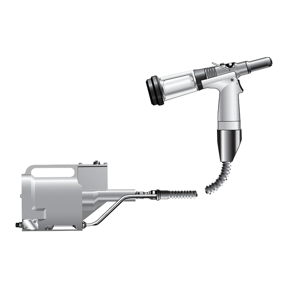
I n t e n t o f U s e G2-s is a hydro-pneumatic tool designed to place Avdel ® FASTENER SIZE ( breakstem fasteners at high speed making it ideal for batch or FASTENER flow-line assembly in a wide variety of applications throughout all NAME industries. -
Seite 6: Putting Into Service
P u t t i n g i n t o S e r v i c e E n g l i s h A i r S u p p l y All tools are operated with compressed air at an optimum pressure of 5.5 bar. We recommend the use of pressure regulators and filtering systems on the main air supply. -
Seite 7: Nose Assemblies
N o s e A s s e m b l i e s F i t t i n g I n s t r u c t i o n s I M P O R T A N T The air supply must be disconnected when fitting or removing nose assemblies. - Seite 8 N o s e A s s e m b l i e s E n g l i s h I M P O R T A N T Nose assemblies do NOT include nose tips. Nose tips must be ordered separately. A tool (except part number 71400-00039) must always be fitted with the correct nose assembly and nose tip for your fastener and must be ordered separately, refer to the ‘NOSE TIPS’...
- Seite 9 N o s e A s s e m b l i e s s e e F A S T E N E R N O S E T I P ( m m ) T Y P E 2 b e l o w MATERIAL NAME...
-
Seite 10: Accessories
A c c e s s o r i e s E n g l i s h S t e m D e f l e c t o r The stem deflector is a very simple alternative to the standard stem collector and allows access in restricted areas. -
Seite 11: Swivel Heads
A c c e s s o r i e s S w i v e l H e a d s Instead of a nose assembly, a swivel head can be fitted to a base tool. It allows 360° rotation of the tool about the nose tip and allows access into many applications otherwise too restrictive. -
Seite 12: Preparing The Base Tool
A c c e s s o r i e s E n g l i s h P r e p a r i n g t h e b a s e t o o l • Disconnect the air supply. Base tool to receive a nose assembly •... -
Seite 13: Fitting Instructions
A c c e s s o r i e s The fitting and servicing procedures for both types of head are almost identical. Differences are clearly indicated. I M P O R T A N T PRIOR to fitting a swivel head, the base tool must be adapted. See previous page. The air supply must be disconnected when fitting or removing swivel heads. -
Seite 14: Swivel Head Servicing Instructions
A c c e s s o r i e s E n g l i s h S w i v e l H e a d S e r v i c i n g I n s t r u c t i o n s Swivel heads should be serviced at weekly intervals. -
Seite 15: Servicing The Tool
S e r v i c i n g t h e To o l I M P O R T A N T Read safety instructions on page 4. The employer is responsible for ensuring that tool maintenance instructions are given to the appropriate personnel. The operator should not be involved in maintenance or repair of the tool unless properly trained. - Seite 16 S e r v i c i n g t h e To o l E n g l i s h M o l y k o t e 5 5 M G r e a s e S a f e t y D a t a First Aid SKIN: Flush with water.
-
Seite 17: Annually
S e r v i c i n g t h e To o l A n n u a l l y (or every 500,000 cycles whichever is the soonest) Annually or every 500,000 cycles the tool should be completely dismantled and new components should be used where worn, damaged or recommended. -
Seite 18: Head Assembly
S e r v i c i n g t h e To o l E n g l i s h H e a d A s s e m b l y • Unscrew retaining nut 26 and pull off stem collector assembly, items 18, 20, 21, 22, 23, 24, 25 and ‘O’ ring 19. •... -
Seite 19: Intensifier
S e r v i c i n g t h e To o l I n t e n s i f i e r • Disconnect the air supply. • Remove cover plate 58 and gasket 83 by removing screws 98 (4 off) and washers 99 (4 off). •... - Seite 20 N o t e s E n g l i s h...
- Seite 21 G e n e r a l A s s e m b l y o f P i s t o l 7 1 4 0 0 - 0 2 0 0 0 ( s )
- Seite 22 P a r t s L i s t f o r 7 1 4 0 0 - 0 2 0 0 0 ( s ) E n g l i s h...
- Seite 23 G e n e r a l A s s e m b l y o f I n t e n s i f i e r 7 1 4 2 0 - 0 2 0 0 0 ( s )
- Seite 24 P a r t s L i s t f o r 7 1 4 2 0 - 0 2 0 0 0 ( s ) E n g l i s h...
-
Seite 25: Oil Details
P r i m i n g Priming is ALWAYS necessary after the tool has been dismantled and prior to operating. It may also be necessary to restore the full stroke after considerable use, when the stroke may be reduced and fasteners are not fully placed by one operation of the trigger. O i l D e t a i l s The recommended oil for priming is Hyspin VG32 available in 0.5l (part number 07992-00002) or one gallon containers (part number 07992-00006). -
Seite 26: Priming Procedure
P r i m i n g E n g l i s h P r i m i n g P ro c e d u r e I M P O R T A N T All operations should be carried out on a clean bench, with clean hands in a clean area. Ensure that the new oil is perfectly clean and free from air bubbles. -
Seite 27: Fault Diagnosis
F a u l t D i a g n o s i s S Y M P T O M P O S S I B L E C A U S E R E M E D Y PA G E R E F More than one Air leak... - Seite 28 N o t e s E n g l i s h...
- Seite 29 N o t e s...
- Seite 30 D e c l a r a t i o n o f C o n f o r m i t y We, Avdel UK Limited, Mundells, Welwyn Garden City, Herts, AL7 1EZ declare under our sole responsibility that the product: Model G2-s Serial No.
- Seite 31 S o m m a i re F r a n ç a i s Règles de Sécurité Caractéristiques de l’outil Dimensions de l’outil Utilisation prévue Gamme de fixations Numérotation des pièces Mise en service Alimentation pneumatique Procédure d’utilisation Réglage de l’extraction à dépression Ensembles de nez Sélection des nez Instructions de montage et d’entretien...
-
Seite 32: Règles De Sécurité
R è g l e s d e S é c u r i t é Toute personne participant à l'installation, à l'utilisation ou à l'entretien de cet outil doit lire attentivement ce manuel. Ne pas employer à d'autres usages que celui prévu. Ne pas utiliser avec cet outil d'autres matériels que ceux recommandés et fournis par Avdel. -
Seite 33: Caractéristiques De L'outil
C a r a c t é r i s t i q u e s t e c h n i q u e s F r a n ç a i s C a r a c t é r i s t i q u e s d e l ’ o u t i l Pression d’air Minimum - Maximum 5 - 7 bars... -
Seite 34: Utilisation Prévue
U t i l i s a t i o n p r é v u e G a m m e d e f i x a t i o n s Le G2-s est un outil oléo-pneumatique destiné à la pose à DIMENSION DE LA FIXATION cadence rapide de rivets à... -
Seite 35: Mise En Service
M i s e e n s e r v i c e F r a n ç a i s A l i m e n t a t i o n P n e u m a t i q u e Tous les outils fonctionnent à... -
Seite 36: Ensembles De Nez
E n s e m b l e s d e n e z I n s t r u c t i o n s d e M o n t a g e I M P O R T A N T Débrancher l'alimentation pneumatique avant de monter ou démonter les ensembles de nez. - Seite 37 E n s e m b l e s d e n e z F r a n ç a i s Ty p e s d e N e z I M P O R T A N T Les ensembles de nez NE COMPRENNENT PAS les nez.
- Seite 38 E n s e m b l e s d e n e z Ty p e s d e N e z F I X A T I O N voir N E Z ( m m ) N E Z D E ci-dessous Ø...
-
Seite 39: Déflecteur De Tiges
A c c e s s o i re s F r a n ç a i s D é f l e c t e u r d e T i g e s Le déflecteur de tiges est un accessoire très simple qui s’installe en remplacement du récupérateur de tiges normal, en permettant DEFLECTEUR DE TIGES l’accès à... -
Seite 40: Têtes Pivotantes
A c c e s s o i re s T ê t e s P i v o t a n t e s A la place d’un ensemble de nez, il est possible de monter sur un outil de base une tête pivotante. Elle permet une rotation de l’outil sur 360º... - Seite 41 A c c e s s o i re s F r a n ç a i s P r é p a r a t i o n d e l ’ o u t i l d e b a s e •...
-
Seite 42: Instructions De Montage
A c c e s s o i re s Les procédures de montage et d’entretien sont presque identiques pour les deux types de tête. Les différences sont clairement indiquées. I M P O R T A N T AVANT de monter une tête pivotante, il est nécessaire d’adapter l’outil. Voir page précédente. Débrancher l’alimentation pneumatique avant de monter ou de déposer une tête pivotante. - Seite 43 A c c e s s o r i e s F r a n ç a i s I n s t r u c t i o n s d ’ e n t r e t i e n d e l a t ê t e p i v o t a n t e Les têtes pivotantes doivent être entretenues chaque semaine.
-
Seite 44: Entretien De L'outil
E n t re t i e n d e l ’ o u t i l I M P O R T A N T Lire les instructions de sécurité de la page 34. Il appartient à l'employeur de faire en sorte que les instructions de maintenance des outils soient confiées aux personnes compétentes. - Seite 45 E n t re t i e n d e l ’ o u t i l F r a n ç a i s I n f o r m a t i o n s d e s é c u r i t é , g r a i s s e M o l y k o t e 5 5 m Premiers secours PEAU : Rincer à...
-
Seite 46: Tous Les Ans
E n t re t i e n d e l ’ o u t i l To u s l e s a n s (ou tous les 500.000 cycles, au premier des deux termes) Une fois par an ou tous les 500 000 cycles, l’outil doit être entièrement démonté et les pièces usées, endommagées ou faisant l’objet d’une recommandation doivent être remplacées. -
Seite 47: Ensemble Tête
E n t re t i e n d e l ’ o u t i l F r a n ç a i s E n s e m b l e T ê t e • Dévisser l’écrou de retenue 26 et extraire l’ensemble récupérateur de tiges, repères 18, 20, 21, 22, 23, 24, 25 ainsi que le joint torique 19. -
Seite 48: Amplificateur
E n t re t i e n d e l ’ o u t i l A m p l i f i c a t e u r • Débrancher l'alimentation pneumatique. • Enlever la plaque de fermeture 58 et le joint 83 en retirant les 4 vis 98 et les quatre rondelles 99. •... - Seite 49 N o t e s F r a n ç a i s...
- Seite 50 Assemblage général du pistolet 71400-02000(S)
- Seite 51 L i s t e d e p i è c e s 7 1 4 0 0 - 0 2 0 0 0 F r a n ç a i s...
- Seite 52 Assemblage général de l’amplificateur 71420-02000(S)
- Seite 53 L i s t e d e p i è c e s 7 1 4 2 0 - 0 2 0 0 0 ( s ) F r a n ç a i s...
-
Seite 54: ' H U I L E
P l e i n d ’ h u i l e Le plein d'huile est toujours nécessaire après un démontage de l'outil et avant toute utilisation. Il peut également être utile pour restaurer la totalité de la course après une utilisation prolongée, si l'on constate que la course diminue et que les fixations ne sont pas complètement posées en une seule action sur la gâchette. -
Seite 55: Procédure De Plein D'huile
P l e i n d ’ h u i l e F r a n ç a i s P ro c é d u r e d e p l e i n d ’ h u i l e I M P O R T A N T Toutes ces opérations doivent être effectuées sur un établi propre, avec des mains propres et dans un endroit propre. - Seite 56 D i a g n o s t i c d e s p a n n e s S Y M P T O M E C A U S E P O S S I B L E R E M E D E PA G E D E R E F Il faut plus d'une action...
- Seite 57 N o t e s F r a n ç a i s...
- Seite 58 N o t e s...
- Seite 59 D é c l a r a t i o n d e c o n f o r m i t é Nous, Avdel UK Limited, Mundells, domiciliés Welwyn Garden City, Herts, AL7 1EZ, Royaume-Uni, déclarons sous notre seule responsabilité...
- Seite 60 I n h a l t s a n g a b e D e u t s c h Sicherheitsvorschriften Technische Daten Geräteabmessungen Arbeitsbereich Nietsortiment Teilenummerierung Inbetriebnahme Druckluftversorgung Betrieb Einstellen der Absaugung Ausrüstungen Auswahl der Mundstücke Einbau- und Wartungsanweisungen 69&70 Zubehör Greifteilabweiser...
-
Seite 61: Sicherheitsvorschriften
S i c h e r h e i t s v o r s c h r i f t e n Diese Betriebsanleitung muss von den für die Installation, Verwendung und Wartung zuständigen Personen gelesen werden, wobei den folgenden Sicherheitsvorschriften besondere Aufmerksamkeit zu widmen ist. Nicht zweckentfremdet verwenden. -
Seite 62: Technische Daten
Te c h n i s c h e D a t e n D e u t s c h Te c h n i s c h e G e r ä t e d a t e n Luftdruck Minimum - Maximum 5 - 7 bar... -
Seite 63: Nietsortiment
A r b e i t s b e re i c h N i e t s o r t i m e n t Das Druckluftgerät G2s wurde zum Setzen von Avdel®-Blindnieten NIETGRÖSSE ( bei hohen Geschwindigkeiten konstruiert. Es ist auf diese Weise ideal ”... -
Seite 64: Druckluftversorgung
I n b e t r i e b n a h m e D e u t s c h D r u c k l u f t v e r s o rg u n g Alle Geräte werden durch Druckluft betätigt. Der optimale Druck beträgt 5,5 bar. Wir empfehlen die Verwendung von Druckreglern und Filtersystemen in der Hauptluftversorgung. - Seite 65 A u s r ü s t u n g e n E i n b a u a n w e i s u n g e n H I N W E I S Die Druckluftversorgung muss während des Einbaus oder des Entfernens von Ausrüstungen abgetrennt werden. Die fettgedruckten Positionsnummern beziehen sich auf die Ausrüstungskomponenten in allen drei Mundstücktabellen.
- Seite 66 A u s r ü s t u n g e n D e u t s c h M u n d s t ü c k e H I N W E I S Ausrüstungen enthalten KEINE Mundstücke. Mundstücke sind separat zu bestellen. Ein Gerät (mit Ausnahme der Artikelnummer 71400-00039) muss immer mit der korrekten Ausrüstung und einem für den zu setzenden Niet geeigneten Mundstück ausgestattet sein, die gesondert bestellt werden müssen.
- Seite 67 A u s r ü s t u n g e n M u n d s t ü c k e N I E T M U N D S T Ü C K ( m m ) s i e h e M U N D S T Ü...
-
Seite 68: Auswerfer
Z u b e h ö r D e u t s c h G r e i f t e i l a b w e i s e r Greifteilabweiser eine einfache Alternative serienmäßigen Greifteil-Auffangbehälter und erlaubt Zugang zu GREIFTEILABWEISER Bereichen mit beschränktem Raum. -
Seite 69: Drehköpfe
Z u b e h ö r D r e h k ö p f e Anstatt der kompletten Ausrüstung kann ein Drehkopf auf einem Grundgerät montiert werden, wodurch eine Drehung von 360° des Gerätes um das Mundstück sowie Zugang zu vielen Anwendungen, der anderweitig zu beschränkt ist, erlaubt werden. Es stehen zwei Drehkopftypen zur Verfügung: der gerade Drehkopf mit einem etwas von der Mittellinie des Gerätekopfes versetzten Mundstück und der rechtwinklige Drehkopf mit dem Mundstück in einer senkrechten Achse zum Kopf des Gerätes. -
Seite 70: Fähigkeit Des Rechtwinkligen Drehkopfes
Z u b e h ö r D e u t s c h Vo r b e r e i t u n g d e s G r u n d g e r ä t e s •... - Seite 71 Z u b e h ö r Die Einbau- und Wartungsverfahren für beide Kopftypen sind fast identisch. Unterschiede sind klar gekennzeichnet. H I N W E I S VOR dem Einbau des Drehkopfs ist eine Anpassung des Grundgerätes vorzunehmen (siehe vorherige Seite). Beim Einbau oder Entfernen von Drehköpfen muss die Druckluftversorgung abgetrennt werden.
- Seite 72 Z u b e h ö r D e u t s c h A n l e i t u n g z u r D r e h k o p f w a r t u n g Drehköpfe sind in wöchentlichen Intervallen zu warten.
-
Seite 73: Wartung Des Gerätes
Wa r t u n g d e s G e r ä t e s H I N W E I S Die Sicherheitsvorschriften auf Seite 64 lesen. Der Arbeitgeber trägt die Verantwortung sicherzustellen, dass die Gerätewartungsanweisungen dem entsprechenden Personal ausgehändigt werden. Ohne fachgerechte Ausbildung sollte der Bediener nicht zu Wartungs- oder Reparaturarbeiten am Gerät herangezogen werden. - Seite 74 Wa r t u n g d e s G e r ä t e s D e u t s c h M o l y k o t e 5 5 m S c h m i e r f e t t s i c h e r h e i t s d a t e n Erste Hilfe HAUT: Mit Wasser abspülen.
-
Seite 75: Jährlich
Wa r t u n g d e s G e r ä t e s J ä h r l i c h (oder alle 500.000 Zyklen, was immer zuerst eintritt) Das Gerät muss jährlich oder alle 500.000 Arbeitstakte komplett zerlegt werden und verschlissene, beschädigte oder empfohlene Bauteile sind auszuwechseln. - Seite 76 Wa r t u n g d e s G e r ä t e s D e u t s c h K o p f k o m p l e t t • Kreuzlochmutter 26 abschrauben und Greifteil-Auffangbehälter (Pos. 18, 20, 21, 22, 23, 24 und 25) sowie O-Ring 19 abziehen. •...
- Seite 77 Wa r t u n g d e s G e r ä t e s D r u c k ü b e r s e t z e r • Druckluftversorgung abtrennen. • Die Schrauben 98 (4 Stück) und Scheiben 99 (4 Stück) entfernen, so dass die Abdeckplatte 58 und die Dichtung 83 entfernt werden können. •...
- Seite 78 A n m e r k u n g e n D e u t s c h...
- Seite 79 Übersichtszeichnung der Pistole 71400-02000(s)
- Seite 80 E r s a t z t e i l l i s t e f ü r 7 1 4 0 0 - 0 2 0 0 0 D e u t s c h...
- Seite 81 Übersichtszeichnung des Druckübersetzers 71420-02000(S)
- Seite 82 E r s a t z t e i l l i s t e f ü r 7 1 4 2 0 - 0 2 0 0 0 ( S ) D e u t s c h...
- Seite 83 Ö l w e c h s e l Das Auffüllen mit Öl ist IMMER nach dem Zerlegen des Gerätes und vor der Inbetriebnahme erforderlich. Es könnte auch notwendig sein, nach längerem Gebrauch den vollen Hub wiederherzustellen, da bei geringerem Hub die Niete durch eine Betätigung des Auslösers nicht richtig gesetzt werden.
- Seite 84 Ö l w e c h s e l D e u t s c h A u f f ü l l v o rg a n g H I N W E I S Sämtliche Arbeitsvorgänge sind auf einer sauberen Werkbank, mit sauberen Händen und in einem sauberen Bereich durchzuführen.
- Seite 85 B e s e i t i g e n v o n S t ö r u n g e n S Y M P T O M M Ö G L I C H E U R S A C H E A B H I L F E SEITENVERWEIS Mehr als eine...
- Seite 86 N o t i z e h D e u t s c h...
- Seite 87 N o t i z e h...
- Seite 88 K o n f o r m i t ä t s e r k l ä r u n g Wir, Avdel UK Limited, Mundells, Welwyn Garden City, Herts, AL7 1EZ, erklären unter unserer alleinigen Verantwortung, dass das Produkt: Modell G2-s Seriennummer, ..........
- Seite 89 I n d i c e I t a l i a n o Norme di sicurezza Specifiche attrezzo Dimensioni attrezzo Ambito di utilizzo Gamma rivetti Codici parte Messa in servizio Alimentazione aria Procedura operativa Regolazione valvola di aspirazione Testate Selezione naselli Istruzioni di montaggio e di manutenzione 99 &...
- Seite 90 N o r m e d i s i c u re z z a Il presente manuale d'istruzione deve essere letto dal personale addetto all'installazione, funzionamento e manutenzione dell'attrezzo prestando particolare attenzione alle norme di sicurezza sotto elencate. Non utilizzare l'attrezzo per scopi diversi da quelli specificati. Non usare con il presente attrezzo/macchina equipaggiamenti che non siano raccomandati e forniti da Avdel.
- Seite 91 S p e c i f i c h e a t t re z z o I t a l i a n o S p e c i f i c h e a t t r e z z o Pressione aria minima - massima 5-7 bar...
- Seite 92 A m b i t o d i u t i l i z z o G a m m a r i v e t t i L’attrezzo oleopneumatico G2s è stato progettato per il piazzamento DIMENSIONI rapido dei rivetti Avdel®. È l’attrezzo ideale da usare nelle linee o POLLICI TIPO isole di assemblaggio in un’ampia gamma di applicazioni e in tutti i...
- Seite 93 M e s s a i n s e r v i z i o I t a l i a n o A l i m e n t a z i o n e a r i a Tutti gli attrezzi vengono fatti funzionare con aria compressa con una pressione ottimale di 5,5 bar.
- Seite 94 Te s t a t e I s t r u z i o n i d i m o n t a g g i o I M P O R T A N T E L'aria dell’alimentazione va scollegata quando si deve montare o smontare una testata. I numeri in grassetto si riferiscono ai componenti delle testate riportati in tutte le tre tabelle dei naselli.
- Seite 95 Te s t a t e I t a l i a n o N a s e l l i I M P O R T A N T E Le testate NON comprendono i naselli, che devono essere ordinati a parte. Fatta eccezione per il 71400-00039, ogni attrezzo deve sempre montare la testata e il nasello adatti al rivetto: tali componenti vengono forniti separatamente;...
- Seite 96 Te s t a t e N a s e l l i v e d e r e R I V E T T O N A S E L L O ( m m ) N A S E L L I s o t t o MATERIALE TIPO...
- Seite 97 A c c e s s o r i I t a l i a n o G r u p p o D e f l e t t o r e Il deflettore può facilitare l’utilizzo dell’attrezzo in situazioni di accesso difficoltoso.
- Seite 98 A c c e s s o r i Te s t a t e G i r e v o l i L’attrezzo base può montare al posto della testata standard una testata girevole. Tale componente consente all’attrezzo una rotazione di 360°...
- Seite 99 A c c e s s o r i I t a l i a n o P r e p a r a z i o n e a t t r e z z o b a s e •...
- Seite 100 A c c e s s o r i Le procedure di montaggio e di manutenzione sono quasi identiche per entrambi i tipi di testata. Le differenze esistenti vengono indicate chiaramente. I M P O R T A N T E PRIMA di montare una testata girevole occorre preparare l’attrezzo base (vedere pagina precedente).
- Seite 101 A c c e s s o r i I t a l i a n o I s t r u z i o n i d i m a n u t e n z i o n e t e s t a t a g i r e v o l e Le testate girevoli devono essere sottoposte a manutenzione a intervalli settimanali.
- Seite 102 M a n u t e n z i o n e d e l l ’ a t t re z z o I M P O R T A N T E Leggere le norme di sicurezza a pagina 82. È...
- Seite 103 M a n u t e n z i o n e d e l l ’ a t t re z z o I t a l i a n o S c h e d a d i s i c u r e z z a g r a s s o M o l y k o t e 5 5 m Pronto soccorso PELLE: Lavare abbondantemente con acqua.
- Seite 104 M a n u t e n z i o n e d e l l ’ a t t re z z o M a n u t e n z i o n e a n n u a l e (o da effettuare al compimento di 500.000 cicli, a seconda dell'evento che si verifica prima) Ogni anno (oppure raggiunti 500.000 cicli di lavoro se usato intensamente) l'attrezzo va completamente smontato e vanno sostituite le parti indicate dal fabbricante e le parti usurate o danneggiate.
- Seite 105 M a n u t e n z i o n e d e l l ’ a t t re z z o I t a l i a n o G r u p p o Te s t a •...
- Seite 106 M a n u t e n z i o n e d e l l ’ a t t re z z o I n t e n s i f i c a t o r e • Scollegare l'alimentazione dell’aria.
- Seite 107 N o t e I t a l i a n o...
- Seite 108 S c h e m a g e n e r a l e a t t re z z o 7 1 4 0 0 - 0 2 0 0 0 ( s )
- Seite 109 E l e n c o c o m p o n e n t i p e r 7 1 4 0 0 - 0 2 0 0 0 ( s ) I t a l i a n o...
- Seite 110 Schema generale intensificatore 71420-02000(s)
- Seite 111 E l e n c o c o m p o n e n t i p e r 7 1 4 2 0 - 0 2 0 0 0 ( s ) I t a l i a n o...
- Seite 112 R a b b o c c o d e l l ’ o l i o Dopo che l'attrezzo è stato smontato e prima di metterlo in funzione occorre SEMPRE effettuare il rabbocco dell'olio. Dopo che l'attrezzo è stato usato considerevolmente potrà anche essere necessario ripristinare completamente la corsa, nel caso in cui l'ampiezza di questa si sia ridotta e non si riesca a ribadire completamente i rivetti con un singolo azionamento del grilletto.
- Seite 113 R a b b o c c o d e l l ’ o l i o I t a l i a n o P ro c e d u r a d i r a b b o c c o I M P O R T A N T E Tutte le operazioni di manutenzione o riparazione devono essere eseguite su un banco di lavoro pulito, con mani pulite e in un'area pulita.
- Seite 114 I n d i v i d u a z i o n e g u a s t i S I N T O M O C A U S A P O S S I B I L E R I M E D I O PA G .
- Seite 115 D i c h i a r a z i o n e d i c o n f o r m i t à Noi, Avdel UK Limited, Mundells, Welwyn Garden City, Herts, AL7 1EZ, Gran Bretagna, dichiariamo sotto la nostra esclusiva responsabilità...
- Seite 116 Tel: +82 31 798 6340 Email: info@acument.com.au Email: AvdelDeutschland@acument.com Fax: +82 31 798 6342 Email: info@acumentkorea.com CANADA ITALY Avdel Canada, a Division of Acument Avdel Italia S.r.l. SPAIN Canada Limited Viale Lombardia 51/53 Avdel Spain S.A. 87 Disco Road 20047 Brugherio (MI)