Inhaltsverzeichnis
Werbung
Verfügbare Sprachen
Verfügbare Sprachen
Quicklinks
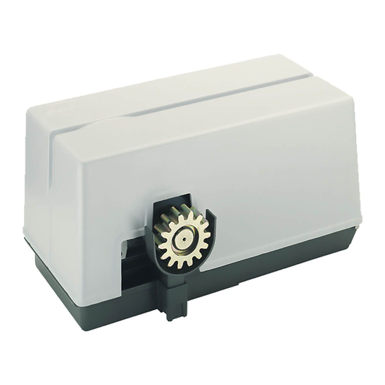
SUPER 2200 3P
Con funzionamento a uomo presente se le fotocellule o le coste sono guaste.
Avec travail avec homme present, dans le cas de panne de sécurité.
With functioning in dead man mode when the safety devices are failing.
Mit arbeit im mannsbeisein im fall eines ausfalls der Sicherheiten.
Con funcionamiento a hombre presente en caso de averías con los accesorios de seguridad.
Operatore
Operateur
Operator
Torantrieb
Operador
SUPER 2200 3P
ITALIANO pag. 05 / FRANÇAIS pag. 10 / ENGLISH page 15 / DEUTSCH pag. 20 / ESPAÑOL pag. 25
Conforme alle normative in vigore.
Conforme aux Normes en vigueur.
According to current European Norms.
In Übereinstimmung mit der aktuellen Normen.
En conformidad a las Normas en vigor.
Alimentazione
Peso max cancello
Alimentation
Poids maxi portail
Power Supply
Max gate weight
Stromspannung
Max Torgewicht
Alimentacion
Peso máx verja
400V 50Hz
2200 kg / 4840 lbs
con / avec / with / mit
OPERATORE IRREVERSIBILE PER CANCELLI SCORREVOLI
OPERATEUR IRREVERSIBLE POUR PORTAILS COULISSANTES
IRREVERSIBLE OPERATOR FOR SLIDING GATES
SELBSTHEMMENDER TORANTRIEB FÜR SCHIEBETOREN
OPERADOR IRREVERSIBLE PARA VERJAS CORREDERAS
Spinta max
Poussée maxi
Max Thrust
Max Schubkraft
Max Empuje
290 kg / 639 lbs
S1/R2
Coppia max
codice
Couple maxi
code
Max torque
code
Max. Drehmoment
code
Coppia max
codigo
87 Nm
AA30082
Werbung
Inhaltsverzeichnis

Verwandte Anleitungen für RIB SUPER 2200 3P


Inhaltszusammenfassung für RIB SUPER 2200 3P
- Seite 1 SUPER 2200 3P con / avec / with / mit S1/R2 OPERATORE IRREVERSIBILE PER CANCELLI SCORREVOLI OPERATEUR IRREVERSIBLE POUR PORTAILS COULISSANTES IRREVERSIBLE OPERATOR FOR SLIDING GATES SELBSTHEMMENDER TORANTRIEB FÜR SCHIEBETOREN OPERADOR IRREVERSIBLE PARA VERJAS CORREDERAS Con funzionamento a uomo presente se le fotocellule o le coste sono guaste.
- Seite 2 à clé). chiave). 2° - Per la sezione ed il tipo dei cavi la RIB consiglia di utilizzare un cavo di tipo 2° - En ce qui concerne la section et le type des câbles, le conseil de la RIB est celui d’utiliser un câble de type H05RN-F présentant une section minimale...
-
Seite 3: Installation
Installing it inside the control panel key locked container). Schluesselkatsten in einem Panzergehaeuse) 2° - As far as the cable section and the cable kind are concerned, RIB suggests 2° - RIB empfiehlt den Kabeltyp H05RN-F mit einem minimalen Querschnitt von... - Seite 4 (por ejemplo instalándolo dentro de un panel cerrado a llave). 2° - Para la sección y el tipo de los cables, la RIB aconseja utilizar cables de tipo H05RN-F con sección mínima de 1,5mm e igualmente atenerse a la norma IEC 364 y a las normas de instalación del propio País.
- Seite 5 LAYOUT IMPIANTO A - Operatore SUPER 2200 3P B - Fotocellule esterne C - Cremagliera D - Selettore a chiave E - Antenna radio F - Lampeggiatore H - Colonnina portafotocellula I - Fotocellula per protezione interna L - Costa meccanica...
- Seite 6 INSTALLAZIONE SUPER 2200 3P ONTROLLO PRE-INSTALLAZIONE - IL CANCELLO DEVE MUOVERSI SENZA ATTRITI - N.B. È obbligatorio uniformare le caratteristiche del cancello alle norme e leggi vigenti. La porta può essere automatizzata solo se in buono stato e se rispondente alla norma EN 12604.
-
Seite 7: Sicurezze Elettriche
ICUREZZE ELETTRICHE Per un cancello scorrevole con peso superiore a 300 kg è obbligatorio installare 2 coppie di fotocellule e costole mobili in numero sufficiente a coprire eventuali punti di schiacciamento e convogliamento (Fig. 6). Le fotocellule devono essere poste a un altezza variabile da 40 a 60 cm. -
Seite 8: Collegamenti Elettrici
COLLEGAMENTI ELETTRICI S1/R2 cod. BA20085... - Seite 9 A - CONNESSIONI SW S1 E’ OBBLIGATORIO SETTARE LA SCHEDA CON DIP 13 IN POSIZIONE ON. L1 - N ALIMENTAZIONE 230 VAC 50/60 HZ (ESEGUITA IN FABBRICA) TORQUE NON DISPONIBILE LAMPEGGIATORE (MAX 40 W) NON TOCCARE IL PONTICELLO ! SW S1 SW S1 SE VIENE RIMOSSO L’OPERATORE NON FUNZIONA! COLLEGAMENTO DI INTERFACCIA AI MORSETTI JC DELLA SCHEDA...
- Seite 10 RELE’ E COMANDO MOTORE - SETTAGGI K1 => Comando direzione apertura SW1 SW2 SW3 - MICROINTERRUTTORI PER PROCEDURE K2 => Comando direzione chiusura DIP 1 CONTROLLO SENSO DI ROTAZIONE DEL MOTORE (ON) (PUNTO C) K3 => Comando lampeggiatore DIP 2 PROGRAMMAZIONE TEMPI (ON) (PUNTO D) Q5 =>...
- Seite 11 UNZIONAMENTO ACCESSORI DI SICUREZZA PULSANTE DI APERTURA (COM-OPEN) A cancello fermo il pulsante comanda il moto di apertura. Se viene azionato durante la FOTOCELLULA (COM-PHOT) chiusura fa riaprire il cancello. DIP 6 OFF => A cancello chiuso se un ostacolo è davanti al raggio delle fotocellule, il FUNZIONE OROLOGIO DEL PULSANTE DI APERTURA cancello non apre.
-
Seite 12: Caratteristiche Tecniche
Se la costa è guasta o impegnata per più di 5 secondi, o se la fotocellula è guasta o ARATTERISTICHE TECNICHE impegnata per più di 60 secondi, i comandi APRE, CHIUDE, K BUTTON e PEDONALE funzioneranno solo ad uomo presente. - Umidità... - Seite 13 OPTIONAL - Per i collegamenti ed i dati tecnici degli accessori attenersi ai relativi libretti di istruzione. ELECOMANDO SUN IT SYNCRO SUN 2CH cod. ACG6052 SUN 4CH cod. ACG6054 SUN CLONE 2CH cod. ACG6056 SUN CLONE 4CH cod. ACG6058 ADIO RICEVITORI AD AUTOAPPRENDIMENTO FOTOCELLULE FIT SYNCRO DA PARETE cod.
- Seite 14 RED permette la realizzazione di un impianto con coste fissate anche sull’anta in movimento senza l’adozione di sistemi raccogli cavo. È conforme alla norma EN13849-1:2007 e congiuntamente ad un quadro elettronico RIB è un dispositivo di protezione di Classe 2.
-
Seite 15: Caractéristiques Techniques
SCHÉMA DÉTAILLÉ DE L’INSTALLATION A - Operateur SUPER 2200 3P B - Photocellules p/protec. externe C - Cremaillere D - Selecteur E - Antenne radio F - Signal electrique H - Poteau zingué p/cellule ne I - Photocellules p/protection interne L - Barre palpeuse mécanique fixé... - Seite 16 INSTALLATION SUPER 2200 3P ONTRÔLE PRÉ-INSTALLATION !! LE PORTAIL DOIT SE DÉPLACER SANS FROTTER !! N.B. Il est impératif d’uniformiser les caractéristiques du portail avec les normes et les lois en vigueur. La porte peut être automatisée seulement si elle est en bon état et qu’elle est conforme à...
- Seite 17 ECURITES ELECTRIQUES Pour un portail coulissant de poids supérieur à 300 kg, il est obligatoire d’installer 2 couples de photocellules et des montants mobiles en nombre suffisant pour occuper tous les espaces dangereux (fig. 6). Les photocellules doivent être installé à une hauteur variant de 40 à...
-
Seite 18: Branchements Électriques
BRANCHEMENTS ÉLECTRIQUES S1/R2 code BA20085... - Seite 19 A - BRANCHEMENTS SW S1 IL EST OBLIGATOIRE DE INSTAURER LA FICHE AVEC DIP 13 EN POSITION “ON”. L1 - N ALIMENTATION 230 VCA 50/60 HZ (EXÉCUTÉE EN FABRIQUE) CLIGNOTANT (MAX 40 W) LOW SPEED PAS DISPONIBLE TORQUE PAS DISPONIBLE CONNEXION DE INTERFACE À...
- Seite 20 RELAIS ET COMMANDE MOTEUR - RÉGLAGES K1 => Commande direction ouverture K2 => Commande direction fermeture SW1 SW2 SW3 - MICROINTERRUPTEURS POUR PROCÉDURES K3 => Commande clignotant DIP 1 CONTRÔLE DU SENS DE ROTATION DU MOTEUR (ON) (POINT C) Q5 => TRIAC - Commande direction de ouverture et fermeture DIP 2 PROGRAMMATION DES DURÉES (ON) (POINT D) DIP 2-1 PROGRAMMATION DES LAPS DE TEMPS D’OUVERTURE POUR PIÉTONS (DIP 2...
- Seite 21 À portail arrêté, le bouton-poussoir commande le mouvement d’ouverture. S’il est actionné ONCTIONNEMENT DES ACCESSOIRES DE SÉCURITÉ durant la fermeture, il fait ouvrir de nouveau le portail. FONCTION HORLOGE DU BOUTON-POUSSOIR D’OUVERTURE PHOTOCELLULE (COM-PHOT) Pour utiliser la FUNCTION HORLOGE demander S1 avec firmware 05 NOUP pour DIP 6 OFF =>...
-
Seite 22: Solution Des Problemes
Durant toute opération, le bouton-poussoir de STOP exécute l’arrêt du portail. Avec DIP 8 sur ON => Le clignotant et le ronfleur partent 3 secondes avant le Si on appuie sur ce bouton à portail totalement ouvert (ou partiellement en utilisant moteur. - Seite 23 Pour les branchements et les données techniques des accessoires, se conformer aux livrets d’instruction correspondants. OPTIONS - IT SYNCRO METTEUR RADIO SUN SUN 2CH code ACG6052 SUN 4CH code ACG6054 SUN CLONE 2CH code ACG6056 SUN CLONE 4CH code ACG6058 ADIORÉCEPTEURS AUTO-APPRENDISSAGE PHOTOCELLULES MURALES FITSYNCRO code ACG8026...
- Seite 24 RED permet la réalisation d’une installation avec barres palpeuses fixées également sur le battant en mouvement sans l’adoption de systèmes d’assemblage de câbles. Il est conforme à la norme EN13849-1:2007 et associé à un tableau électronique RIB, il est un dispositif de protection de Classe 2.
-
Seite 25: System Lay-Out
SYSTEM LAY-OUT A - SUPER 2200 3P operator B - Photoelectric cells (external) C - Rack D - Key selector E - Tuned aerial F - Flashing lamp H - Galvanized column for P.E. cells I - Photo electric cells (internal) - Seite 26 INSTALLATION SUPER 2200 3P HECKING BEFORE THE INSTALLATION !! THE GATE SHALL MOVE FRICTIONLESS !! N.B.: Gate features must be uniformed with the standards and laws in force. The door/ gate can be automated only if it is in a good condition and its conditions comply with the EN 12604 norm.
-
Seite 27: Electric Safety Devices
LECTRIC SAFETY DEVICES For a sliding gate weighing more than 300 kg it is obligatory to fit 2 pairs of photocells and mobile sensors in such a way as to protect any potentially dangerous openings in the gate (fig. 6). The photocells must be located at a height of between 40 cm and 60 cm. One pair of photocells must be located inside the premises and adjusted so that they cover the entire travel distance of the gate, while the other pair must be located externally between the gateposts. - Seite 28 ELECTRIC CONNECTIONS S1/R2 code BA20085...
- Seite 29 A - CONNEXIONS SW S1 IT IS COMPULSORY TO SET THE DIP 13 OF THE CONTROL PANEL IN THE ON POSITION. L1 - N 230Vac 50/60Hz POWER SUPPLY (TO BE DONE BY THE PROG. PROGRAMMING BUTTON MANUFACTURER) BLINKER (40 W MAX.) LOW SPEED IS NOT AVAILABLE CONNECTION TO JC CONTACTS OF THE CARD R2...
- Seite 30 POINT B - DL7 the RED led for CLOSING - SETTINGS When you press and hold the PROG.Button, if the gate opens with the green led on DIP 1 MOTOR ROTATION DIRECTION CHECK (See Point C) then you may proceed to step 4. DIP 2 PROGRAMMING (See Point D) If the gate moves in the wrong direction compared with the movement leds:...
- Seite 31 DIP4 - ON The RADIO COMMAND perform the step by step cyclic command open- In case there are more couple of photocells, the contacts from all the photocell receivers stop-close-open-stop-etc. could be connected in series. DIP4 - OFF The RADIO COMMAND perform the automatic command: In case the photocells are not installed, this contact must be short circuited with a wire - the open command, if pressed with the gate completely closed jump (from PHOT to COM) to permit the gate to operate.
-
Seite 32: Technical Specifications
Once the failing safety device is repaired, in automatic after 1 second, all standard ECHNICAL SPECIFICATIONS commands that were selected, such as step by step, automatic mode, radio commands and automatic closing start functioning again. - Humidity < 95% without condensation Note 1: during this functioning in dead man mode, in case of damage to the safety - Power voltage 400 Vac 3/PHASE... - Seite 33 OPTIONAL - Per i collegamenti ed i dati tecnici degli accessori attenersi ai relativi libretti di istruzione. IT SYNCRO ADIO TRANSMITTER SUN SUN 2CH code ACG6052 SUN 4CH code ACG6054 SUN CLONE 2CH code ACG6056 SUN CLONE 4CH code ACG6058 FIT SYNCRO PHOTOCELLS for the wall-installation code ACG8026 ODE LEARNIG SYSTEM RADIORECEIVERS The range you can set is 10-20 m, 30÷60 ft.
- Seite 34 RED allows to make a system made with edges fixed to the moving shutter without having to use cable sleeving systems. It complies with EN13849-1:2007 Standard, if installed with an RIB Electronic Board it is a Class-2 Device. code ACG6202...
-
Seite 35: Technische Eigenschaften
ANLAGEN LAY-OUT A - Torantrieb SUPER 2200 3P B - Photozelle Toraussenseitig C - Zahnstange D - Schlusselschalter E - Antenne F - Blinkleuchte H - Verzinkte Metallsäule als Photozellentrager I - Photozelle - Torinnenseitig L - Sicherheitskontaktleiste auf dem Schiebetor... -
Seite 36: Otorbefestigung Und Zahnstange
INSTALLATION SUPER 2200 3P OR DER MONTAGE AUSZUFÜHRENDE ÜBERPRÜFUNGEN !! DAS TOR MUSS REIBUNGSFREI LAUFEN !! ANMERKUNG: Es ist erforderlich, die Charakteristiken des Tors an die geltenden Normen und Gesetze anzupassen. Das Tor kann nur automatisch Angeschlossen werden, wenn es in einem einwandfreien Zustand ist und der EN12604 entspricht. -
Seite 37: Elektrische Sicherheitsvorrichtungen
LEKTRISCHE SICHERHEITSVORRICHTUNGEN Für ein Schiebetor mit einem Gewicht über 300 kg sind 2 Fotozellempaare und eine entsprechende Anzahl von verstellbaren Sicherheitssensoren zur Verriegelung eventueller Zwischenraume zu installieren (Abb. 7). Die Fotozellen sind auf einer variablen Hohe zwischen 40 und 60 cm zu montieren. Ein Fotozellenpaar wird innerhalb des eingezäunten Geländes installiert, wo es den gesamten Fahrweg des Tores abdecken soll. -
Seite 38: Elektroanschlöüsse
ELEKTROANSCHLÖÜSSE S1/R2 Kode BA20085... - Seite 39 A - VERBINDUNGEN SW S1 PFLICHTEINSTELLUNG FÜR STEUERUNG MIT DIP13 AUF POSITION ON. L1 - N STROMVERSORGUNG 230 VAC 50/60 HZ (IN DER FIRMA RADIO STECKVERBINDER FÜR EXTERNEN FUNKEMPFÄNGER 24 VDC AUSGEFÜHRT) BLINKER (MAX. 40 W) PROG. PROGRAMMIERTASTE OBERFLÄCHENANSCHLUSS ZU JC KLEMMEN VON STEUERUNG LOW SPEED NICHT VERFÜGBAR U-V-W...
-
Seite 40: C - Steuerung Motordrehrichtung
F2 T5A Sicherung für Kraftkreis - EINSTELLUNGEN SW1 SW2 SW3 - BETRIEBSMIKROSCHALTER RELAIS UND MOTORSTEUERUNG DIP 1 STEUERUNG MOTORDREHRICHTUNG (EIN) (PUNKT C) K1 => Richtungssteuerung Öffnung DIP 2 ZEITPROGRAMMIERUNG (EIN) (PUNKT D) K2 => Richtungssteuerung Schließung DIP 2 - 1 ZEITPROGRAMMIERUNG ÖFFNUNG FUßGÄNGER (DIP 2 EIN GEFOLGT VON K3 =>... -
Seite 41: Funktionsweise Der Sicherheitseinrichtungen
maximale Pausenzyklus beträgt 5 Minuten, sowohl für den Modus Vollständige Öffnung, als WARNUNG: VERBINDEN SIE STEUERUNG-ZUBEHÖR, NUR WENN ES auch für den Modus Öffnung für Fußgänger. IMPULS-MODUS. Der Pausenzyklus kann mit DIP 3 aktiviert oder deaktiviert werden (AN aktiv). Stellen Sie sicher, dass alle anderen Arten von Steuerung-Zubehör (z.B. Magnetsensoren) auf IMPULS-Modus programmiert ist, da es die Bewegung FUNKTIONSWEISE NACH STROMAUSFALL des Tores ohne aktive Sicherheiten aktiviert. -
Seite 42: Lösung Von Problemen
FUNKTIONSTEST KONTAKTLEISTEN IST NUR DANN MÖGLICH, WENN ES SICH UM BLINKER VORRICHTUNGEN HANDELT, DIE MIT EINEM EIGENEN NETZANSCHLUSS FÜR DIE HINWEIS: Diese Schalttafel kann NUR BLINKER MIT BLINKSCHALTUNGEN (Cod. KONTROLLÜBERWACHUNG VERSEHEN SIND. EINE MECHANISCHE LEISTE KANN NICHT ACG7059) mit Lampen mit max. 40 W versorgen. ÜBERWACHT WERDEN, DESHALB MUSS DIP 12 AUF „AUS“... - Seite 43 Für die Anschlüsse und die technischen Daten der Zubehöre verweisen wir auf die entsprechenden Betriebsanleitungen. OPTIONEN - IT SYNCRO ERNSENDER SUN SUN 2CH Kode ACG6052 SUN 4CH Kode ACG6054 SUN CLONE 2CH Kode ACG6056 SUN CLONE 4CH Kode ACG6058 ELBSTLERNEND FUNKEMPGÄNGER WANDFOTOZELLEN FITSYNCRO Kode ACG8026 einstellbare Reichweite 10÷20 m...
- Seite 44 RED erlaubt die Realisierung einer Anlage mit Kontaktleisten, die auch auf dem sich bewegenden Tor angebracht sein können, ohne dass man Kabelsammelsysteme benötigt. Entspricht der Norm EN13849-1:2007 und in Verbindung mit einer RIB - Schalttafel stellt es eine Schutzvorrichtung der Klasse 2 dar. Kode ACG6202...
-
Seite 45: Características Técnicas
DISPOSICIÒN DE LA INSTALACIÒN folgt von der Seite 39 A - Operador SUPER 2200 3P B - Fotocélulas externas C - Cremallera D - Interruptor de llave E - Antena de radio F - Intermitente H - Columnas para las fotocélulas I - Fotocélulas internas... - Seite 46 INSTALACIÓN SUPER 2200 3P ONTROL PRE-INSTALACIÓN ¡¡LA VERJA TIENE QUE MOVERSE SIN ROCES!! IMPORTANTE. Es obligatorio uniformar las características de la verja a las normas y leyes en vigor. La puerta puede ser automatizada sólo si se encuentra en buen estado y responde a la norma EN 12604.
-
Seite 47: Desbloqueo De Emergencia
ISPOSITIVOS DE SEGURIDAD ELÉCTRICOS Para cancelas de corredera con un peso superior a 300 kg, es obligatorio instalar dos pares de fotocélulas y bandas móviles en número suficiente para cubrir los posibles puntos de aplastamiento y arrastre (Fig. 6). Las fotocélulas se instalan a una altura variable entre 40 y 60 mm. - Seite 48 CONEXIONES ELÉCTRICAS S1/R2 cód. BA20085...
- Seite 49 A - CONEXIÓN SW S1 ES OBLIGATORIO PROGRAMAR LA PLACA CON DIP 13 EN POSICION ON. L1 - N ALIMENTACIÓN 230 VAC 50/60 HZ (EJECUTADO EN FÀBRICA) LOW SPEED NO DISPONIBLE INTERMITENTE (MÁX 40 W) TORQUE NO DISPONIBLE ¡NO TOCAR EL PUENTE! CONEXIÒN DE INTERFAZ A BORNES JC DE PLACA CARD R2 SW S1 SW S1...
- Seite 50 K1 => Mando dirección apertura - AJUSTES K2 => Mando dirección cierre SW1 SW2 SW3 - MICROINTERRUPTORES PARA PROCEDIMIENTOS K3 => Mando intermitente DIP 1 CONTROL DEL SENTIDO DE ROTACIÓN DEL MOTOR (ON) (PUNTO C) Q5 => TRIAC - Mando direcciòn de abertura y cierre. DIP 2 PROGRAMACIÓN DE LOS TIEMPOS (ON) (PUNTO D) DIP 2-1 PROGRAMACIÓN DE LOS TIEMPOS DE APERTURA PEATONAL (DIP 2 ON...
- Seite 51 PULSADOR DE APERTURA (COM-OPEN) UNCIONAMIENTO DE LOS ACCESORIOS DE SEGURIDAD Con la cancela detenida, el pulsador ordena el movimiento de apertura. Si se lo acciona durante el cierre, vuelve a abrir la cancela. FOTOCÉLULA (COM-PHOT) DIP 6 OFF => cuando se interpone un obstáculo en el rayo de las fotocélulas con la FUNCIÓN RELOJ DEL PULSADOR DE APERTURA cancela cerrada, esta no se abre.
-
Seite 52: Resolución De Problemas
Sólo se apaga cuando la cancela está completamente cerrada. FUNCIONAMIENTO A HOMBRE PRESENTE EN CASO DE AVERÍAS CON LOS ACCESORIOS Durante la programación esta señalización se encuentra activa. DE SEGURIDAD Nota: Si se excede con las botoneras o con las lámparas, la lógica del cuadro electrónico resultará... - Seite 53 OPCIONALES - Para las conexiones y datos técnicos de los accesorios, consultar los manuales respectivos. IT SYNCRO ELEMANDO SUN SUN 2CH cód. ACG6052 SUN 4CH cód. ACG6054 SUN CLONE 2CH cód. ACG6056 SUN CLONE 4CH cód. ACG6058 FOTOCÉLULAS FIT SYNCRO DE PARED cód.
- Seite 54 RED permite realizar una instalación con costas colocadas incluso sobre la hoja en movimiento sin la adopción de sistemas recoge cables. Conforme a la norma EN13849-1:2007. Unido a un cuadro electrónico RIB es un dispositivo de protección de Clase 2.
- Seite 55 We declare under our responsibility that SUPER 2200 3P operator is conform to the following standards: Wir erklaeren das der SUPER 2200 3P den folgenden EN-Normen entspricht: Declaramos, bajo nuestra responsabilidad que el operador SUPER 2200 3P es conforme a la siguientes normas y disposiciones: EN 55014-1...
- Seite 56 SUPER 2200 3P Questo prodotto è stato completamente progettato e costruito in Italia · Ce produit a été complètement développé et fabriqué en Italie · This product has been completely developed and built in Italy · Dieses Produkt wurde komplett in Italien entwickelt und hergestellt · Artìculo totalmente proyectado y producido en Italia...