RIB K500 Gebrauchsanweisungen Und Installation
Selbsthemmender torantrieb fuer schiebetoren
Vorschau ausblenden
Andere Handbücher für K500:
- Handbuch (57 Seiten) ,
- Gebrauchsanweisungen und installation (44 Seiten) ,
- Bedienungsanleitung (57 Seiten)
Inhaltsverzeichnis
Verfügbare Sprachen
Verfügbare Sprachen
Quicklinks
ISTRUZIONI PER L'USO E L'INSTALLAZIONE
INSTRUCTIONS POUR L'UTILISATION ET L'INSTALLATION
OPERATING AND INSTALLATION INSTRUCTIONS
GEBRAUCHSANWEISUNGEN UND INSTALLATION
INSTRUCIONES PARA EL USO Y LA INSTALACIÓN
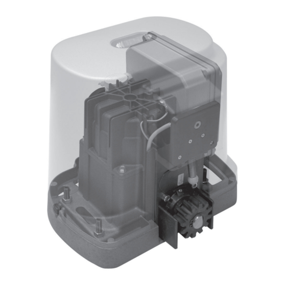
Operatore irreversibile per cancelli scorrevoli - Operateur irreversible pour portails coulissantes
Irreversible operator for sliding gates - Selbsthemmender Torantrieb für Schiebetoren
Mod.
Misure in mm/inch - Mesures en mm/inch - Measurements in mm/inch - Abmessungen in mm/inch - Medidas en mm/pulgadas
Operatore
Operateur
Operator
Torantrieb
Stromspannung
Operador
K500
230V 50/60Hz
K500
230V 50/60Hz
K500
230V 50/60Hz
ventilato/ventilé/
ventilated/mit Ventilator/ventilado
K500
K500
K500
ventilato/ventilé/
ventilated/mit Ventilator/ventilado
Operador irreversible para verjas correderas
Alimentazione
Con quadro
Alimentation
Avec coffret
Power Supply
With control board
Mit Steuerung
Alimentación
Con el tablero de control
K-CRX
K-CRX
120V 60Hz
120V 60Hz
K-CRX
120V 60Hz
K-CRX
K500
Peso max cancello
Poids maxi du portail
Max gate weight
Max Torgewicht
Peso máx. verja
500Kg / 1103lbs
500Kg / 1103lbs
500Kg / 1103lbs
500Kg / 1103lbs
500Kg / 1103lbs
500Kg / 1103lbs
Pag. 1 di 44
Spinta max
codice
Poussée maxi
code
Max Thrust
code
Max Schubkraft
code
Empuje K
código
N 400
AA33694
N 400
AA33695
N 400
AA33697
N 400
AA33693
N 400
AA33696
N 400
AA33698
I
F
GB
D
ES
Inhaltsverzeichnis

Verwandte Anleitungen für RIB K500


Inhaltszusammenfassung für RIB K500
-
Seite 2: Inhaltsverzeichnis
Pag. 2 di 44 INDICE INDEX Controllo pre-installazione ..................pag.6 Checking before the Installation ................pag.20 Caratteristiche Tecniche ..................pag.6 Technical Features ....................pag.20 Sblocco d’emergenza ....................pag.7 Emergency release system ...................pag.21 Fissaggio motore e cremagliera ................pag.7 Motor and rack fitting .....................pag.21 Fissaggio finecorsa ....................pag.7 Limit switch fitting ....................pag.21 Manutenzione ......................pag.7 Maintenance ......................pag.21... -
Seite 4: Important Safety Instructions
Konformitätszeichen besitzt. Solch ein Geraet muss vor Vandalismus 2° - As far as the cable section and the cable kind are concerned, RIB suggests to use geschuetzt werden(z.B.mit einen Schluesselkatsten in einem Panzergehaeuse) an H05RN-F cable, with a minimum section of 1,5mm , and to follow, In any case, 2°... -
Seite 27: Vor Der Montage Auszuführende Überprüfungen
Pag. 27 di 44 ANLAGEN LAY-OUT 1 - Betriebsgerät K500 2 - Externe Fotozellen 3 - Zahnstange Modul 4 4 - Schlüsselwählschalter 5 - Radioantenne 6 - Blinkleuchte 7 - Laufbegrenzer (Nocken) 8 - Mechanische Kontaktleisten 9 - Pneumatische Kontaktleisten oder... -
Seite 28: Entriegelung
Zementier-Basisplatte, die für den K500 Code ACG8108 geschaffen wurde, angefordert werden. Ebenso kann der K500 mit seiner Basisplatte direkt auf die Zementierplatte positioniert werden, die für den Operator K5 (Code ACG8101) bestimmt ist. Die Basisplatte des K500 verfügt außerdem über 4 Bohrlöcher mit 4 Expansionsschrauben für die Bodenfixierung. -
Seite 29: Elektroanschlüsse
Pag. 29 di 44 ELEKTROANSCHLÜSSE SPARK MOTORANSCHLUSS BUZZER FIT SYNCRO BLOCK oder Schalttafel FLAT COSTA... -
Seite 30: B - Die Mikrobedienungsschalter Einstellen
Pag. 30 di 44 Cod. BC07056 K-CRX 230-50/60Hz Cod. BC07057 K-CRX 120-60Hz B - DIE MIKROBEDIENUNGSSCHALTER EINSTELLEN A - VERBINDUNGEN J1=> BERÜHREN SIE NICHT DEN JUMPER! MIKROBEDIENUNGSSCHALTER FÜR PROZEDUREN WENN ER ENTFERNT WIRD, ZIEHT DER OPERATOR NICHT UM! DIP 1 KONTROLLE MOTOR-DREHRICHTUNG (ON) (PUNKT C) DIP 2 PROGRAMMIERUNG ZEITEN (ON) (PUNKT D) -
Seite 31: Kontrolle Motor-Drehrichtung
Anlage oder der Ausführung von möglichen späteren Kontrollen. Programmierung nicht bei völlig geöffnetem Tor stattfinden. 1 - Nachdem Sie das K500 entblockt haben, stellen Sie die richtige Positionierung des 1 - DIP 1– ON und danach DIP 2 ON positionieren. -
Seite 32: Funktionsweise Des Sicherheitszubehörs
Pag. 32 di 44 AUFMERKSAMKEIT: Wenn JP3 geschlossen wird, ist das Funktion Schwarze heraus nicht aktiv. Wenn JP3 geöffnet ist, ist das Funktion Schwarze heraus aktiv. Bei black out Bei Stromrückfuhr Bei völlig geschlossenem Tor bleibt es geschlossen Während der Öffnungsfase setzt es die Öffnungsfase fort Bei völlig offenem Tor (mit dip 3 OFF) bleibt es geöffnet. -
Seite 33: Zubehör
Pag. 33 di 44 ZUBEHÖR EINZUZEMENTIERENDE PLATTE FIT SYNCRO Code ACG8101 WANDFOTOZELLEN FIT SYNCRO - Code ACG8026 einstellbare Reichweite 10÷20mt 49÷100” Dank einer Synchronisiereinrichtung sind mehrere sich gegenseitig annähernde Paare möglich. Bei mehr als 2 Fotozellenpaare (bis 4), den SENDER SYNCRO mit Code ACG8028 hinzufügen. - Seite 41 Pag. 41 di 44 REGISTRO DI MANUTENZIONE - DOSSIER D’ENTRETIEN MAINTENANCE LOG - WARTUNGSREGISTER - REGISTRO DE MANTENIMIENTO Il presente registro di manutenzione contiene i riferimenti tecnici e le registrazioni delle attività di installazione, manutenzione, riparazione e modifica svolte, e dovrà essere reso disponibile per eventuali ispezioni da parte di organismi autorizzati. Ce dossier d’entretien contient les références techniques et les enregistrements des opérations d’installation, d’entretien, de réparation et de modification effectuées, et devra être rendu disponible pour les inspections éventuelles de part d’orgenismes autorisée This maintenance log contains the technical references and records of installation works, maintenance, repairs and modifications, and must be made available for inspection purposes to authorised bodies.
-
Seite 42: Declaración De Coformidad
We declare under our responsibility that K500 operator is conform to the following standards: Wir erklaeren das der K500 den folgenden EN-Normen entspricht: Declaramos bajo nuestra responsabilidad que los operators K500 es conforme a la siguientes normas y disposiciones: EN 55014-1... - Seite 43 Pag. 43 di 44 NOTE:...
- Seite 44 DSB6x25 Vite TSPEI 6x25 UNI5933 CAL1155 Corona elicoidale CPL1158 Guida porta cilindro DSC3x20Z Vite TSP.CR 3x20 CAL1166 Carcassina + campana motore K500 CPL1159 Coperchio per viti DTE8x40 Vite TE 8x40 UNI5739 CPL1160 Cassetto copri serratura DTB63x25 Vite TCEI 6.3x25 AUTOF.ZINC.