
Verwandte Anleitungen für Wilo Wilo-CronoLine IL 250 series


Inhaltszusammenfassung für Wilo Wilo-CronoLine IL 250 series
- Seite 1 Wilo-CronoLine IL 250... Einbau- und Betriebsanleitung Installation and operating instructions RUS Инструкция по монтажу и эксплуатации...
- Seite 2 Fig. 1 Fig. 2...
- Seite 3 Fig. 3 Fig. 4a Fig. 4b Fig. 5...
- Seite 4 Demontage der Gleitringdichtung / Unmounting the mechanical seal / IL7__ins_01a_0401.wmf IL7__ins_02a_0401.wmf Fig. 6 Fig. 7 IL7__ins_03_0507.wmf ins 04 0401.wmf Fig. 8 Fig. 9 IL7__ins_05a_0506.wmf 6a 040 1.wmf Fig. 10 Fig.11...
- Seite 5 IL7__ins_07_0506.wmf IL7__ins_08_0506.wmf Fig. 12 Fig. 13 IL7__ins_09a_0401.wmf IL7__ins_10_0401.wmf Fig. 14 Fig. 15...
- Seite 6 Montage der Gleitringdichtung / Mounting the mechanical seal / IL7__ins_12_0401.wmf IL7__ins_11a_0401.wmf Fig. 16 Fig. 17 IL7__ins_14a_0401.eps IL7__ins_13_0401.wmf Fig. 18 Fig. 19 IL7__ins_16_0506.wmf IL7__ins_15_0401.wmf Fig. 20 Fig. 21...
- Seite 7 IL7__ins_18a_0401.wmf IL7__ins_17a_0506.wmf Fig. 22 Fig. 23 IL7__ins_19_0401.wmf IL7__ins_20_0506.eps Fig. 24 Fig. 25 IL7__ins_22_0401.wmf IL7__ins_21a_0506.wmf Fig. 26 Fig. 27...
- Seite 8 Motorwechsel / Exchange of the motor / IL7__ins_24a_0506.wmf IL7__ins_27_0506.wmf Fig. 28 Fig. 29 IL7__ins_28_0401.wmf IL7__ins_29_0401.wmf Fig. 30 Fig. 31 IL7__ins_30_0401.wmf Fig. 32...
- Seite 9 Einbau- und Betriebsanleitung Installation and operating instructions Инструкция по монтажу и эксплуатации...
- Seite 10 3 ~ 380 V, 60 Hz andere Spannungen auf Anfrage Kaltleiterfühler Drehzahlumschaltung, Drehzahl- Regelgeräte (Wilo-CR-System) regelung Pol-Umschaltung Motor-Sonderausführung Sonderspannung/-frequenz (auf Anfrage) Explosionsschutz (EEx e, EEx de) Standardausführung; Sonderausführung bzw. Zusatzausrüstung (gegen Mehrpreis) Einbau- und Betriebsanleitung WILO AG 08/2006 Wilo-CronoLine IL 250...
- Seite 11 Personen hervorrufen können Warnung vor elektrischer Spannung Sicherheitshinweise, deren Nichtbeachtung Gefahren für Pumpe/Anlage und deren Funktion hervorrufen können 2.2 Personalqualifikation Das Personal für die Montage muß die entsprechende Qualifikation für diese Arbeiten aufweisen. Einbau- und Betriebsanleitung WILO AG 08/2006 Wilo-CronoLine IL 250...
- Seite 12 Die Betriebssicherheit der gelieferten Anlage ist nur bei bestimmungsmäßiger Ver- wendung entsprechend Abschnitt 1.1 der Betriebsanleitung gewährleistet. Die im Katalog / Datenblatt angegebenen Grenzwerte dürfen auf keinen Fall über- bzw. unterschritten werden. Einbau- und Betriebsanleitung WILO AG 08/2006 Wilo-CronoLine IL 250...
-
Seite 13: Transport Und Zwischenlagerung
Hebezeug darauf achten, dass die Last senkrecht angehoben wird. Ein Schwingen der angehobenen Last vermeiden. Dies kann zum Beispiel durch den Einsatz eines zweiten Flaschenzuges erreicht werden, wobei die Zugrichtung beider unter 30 zur Vertikalen liegen sollte. Einbau- und Betriebsanleitung WILO AG 08/2006 Wilo-CronoLine IL 250... - Seite 14 Pumpenaggregates entsprechen. Das Gewicht ist auf dem Typenschild angegeben. WARNING! Um jede Verspannung zu vermeiden, Pumpenaggregat wie dargestellt anheben. Nicht an den Ringösen oder am freien Wellen-Ende der Antriebsmaschine aufhängen! Fig. 1 Einbau- und Betriebsanleitung WILO AG 08/2006 Wilo-CronoLine IL 250...
-
Seite 15: Beschreibung Von Erzeugnis Und Zubehör
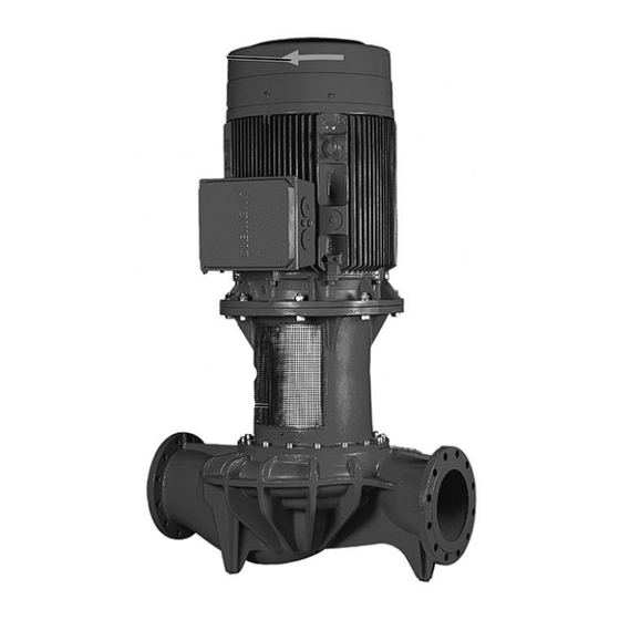
Alle hier beschriebenen Pumpen sind einstufige Niederdruck-Kreiselpumpen in Kompakt-bauweise mit angekuppeltem Motor. Die Gleitringdichtung ist wartungsfrei. Die Pumpen müssen ausreichend verankert auf einen Fundamentsockel gestellt werden. In Verbindung mit einem Regelgerät (Wilo-CR-System) kann die Leistung der Pumpen stufenlos geregelt werden. -
Seite 16: Montage / Aufstellung
Deutsch 5 Montage / Aufstellung 5.1 Vorbereitungen 5.1.1 Auspacken und Überprüfung Die Pumpe muß auf Übereinstimmung mit den Angaben auf dem Lieferschein geprüft werden; etwaige Schäden oder das Fehlen von Teilen müssen der Firma Wilo sofort mitgeteilt werden. Lattenverschläge/Kartons/Umhüllungen Ersatzteile oder Zubehörteile prüfen, die der Pumpe beigepackt sein können. - Seite 17 über dem Saugstutzen der Pumpe sorgen, damit die Pumpe keinesfalls trocken läuft. Der Mindest-Zulaufdruck muß eingehalten werden. Bei Anlagen, die isoliert werden, darf nur das Pumpengehäuse einisoliert werden, nicht Laterne und Motor. Einbau- und Betriebsanleitung WILO AG 08/2006 Wilo-CronoLine IL 250...
- Seite 18 Anschließen der Rohleitungen erst nach Abschluß aller Schweiß- und Lötarbeiten sowie der Reinigung / Spülung des Systems. Flanschabdeckungen an Saug- und Druckstutzen der Pumpe vor dem Anbringen der Rohrleitung entfernen. Einbau- und Betriebsanleitung WILO AG 08/2006 Wilo-CronoLine IL 250...
- Seite 19 In Sonderausführung ist der Motor mit Kaltleiterfühlern ausgestattet. Kaltleiterfühler am Kaltleiterauslösegerät anschließen. An den Klemmen darf nur eine max. Spannung von 7,5V DC angelegt werden, eine höhere Spannung zerstört die Kaltleiterfühler. Einbau- und Betriebsanleitung WILO AG 08/2006 Wilo-CronoLine IL 250...
- Seite 20 Bei Drehstrommotoren mit Y- -Schaltung sicherstellen, dass die Umschalt-punkte zwischen Stern und Dreieck zeitlich sehr eng aufeinander folgen. Längere Umschaltzeiten können zu Pumpenschäden führen. Empfehlung der Zeiteinstellung bei Y- -Einschaltung: Motorleistung Einzustellende Y-Zeit > 30 kW < 5 sec. Einbau- und Betriebsanleitung WILO AG 08/2006 Wilo-CronoLine IL 250...
- Seite 21 Einstellung. Eine etwaige geringe Leckage am Anfang hört auf, wenn die Einlaufphase der Dichtung beendet ist. Unmittelbar nach Abschluß aller Arbeiten müssen alle vorgesehenen Sicherheits- und Schutzeinrichtungen fachgerecht angebracht und in Funktion gesetzt werden. Einbau- und Betriebsanleitung WILO AG 08/2006 Wilo-CronoLine IL 250...
- Seite 22 - Vermeiden, dass ein zu schwacher Gegendruck zu einer Motorüberlastung führt. Um starken Temperaturanstieg im Motor und übermäßige Belastung von Pumpe, Kupplung, Motor, Dichtungen und Lagern zu vermeiden sollten max. 10 Einschalt- vorgänge pro Stunde (h) nicht überschritten werden. Einbau- und Betriebsanleitung WILO AG 08/2006 Wilo-CronoLine IL 250...
-
Seite 23: Wartung
Die Gleitringdichtung ist wartungsfrei. Während der Einlaufzeit können geringfügige Tropfleckagen auftreten. Es ist jedoch von Zeit zu Zeit eine Sichtkontrolle erforderlich. Bei deutlich erkennbarer Leckage ist ein Dichtungswechsel vorzunehmen. Wilo bietet ein Reparatur-Set an, das die für einen Wechsel notwendigen Teile enthält. -
Seite 24: Einbau Der Gleitringdichtung
Motorwelle so drehen, dass Motorwellen-Passfeder und Laufradwellen-Passfeder sich gegenüber stehen. Erste Kupplungshälfte an beiden Passfedern und den Haltescheiben ansetzen (Fig. 20). Gewindebohrung in der Haltescheibe der Laufradwelle auf die Montagebohrung der Kupplungshälfte ausrichten. Einbau- und Betriebsanleitung WILO AG 08/2006 Wilo-CronoLine IL 250... - Seite 25 Die 4 Deckelschrauben (Fig. 26, Pos. 1) eindrehen und mit dem vorgeschriebenen Drehmoment festziehen. Die vier Innensechskant-Schrauben (Arrettier-Stifte; Fig. 26, Pos. 2) nacheinander vollständig eindrehen und festziehen (siehe 7.5). Kupplungsschutz-Bleche montieren (Fig. 27). Motorkabel anklemmen. Einbau- und Betriebsanleitung WILO AG 08/2006 Wilo-CronoLine IL 250...
- Seite 26 Vorgeschriebenes Schraubenanzugsmoment beachten (siehe 7.5) Kupplungspassflächen und Wellenpassflächen kontrollieren, ggf. reinigen. Kupplung montieren und Gleitringdichtung befestigen (siehe Kapitel 7.3.2, Fig. 18 ... 26). Vorgeschriebenes Schraubenanzugsmoment beachten (siehe 7.3) Kupplungsschutz-Bleche montieren (Fig. 27). Motorkabel anklemmen. Einbau- und Betriebsanleitung WILO AG 08/2006 Wilo-CronoLine IL 250...
- Seite 27 über Kreuz Pumpengehäuse – Laterne M16-8.8 anziehen Laterne-Motor Haltescheibe - Laufradwelle Haltescheibe - Motorwelle Grundplatte - Pumpengehäuse M12-10.9 Kupplung Schrauben gleichmäßig, (2 Ausführungen möglich) kreuzweise anziehen M16-10.9 Gleitringdichtung – Laterne Gleitringdichtung (Verdrehsicherung) Einbau- und Betriebsanleitung WILO AG 08/2006 Wilo-CronoLine IL 250...
-
Seite 28: Störungen, Ursachen Und Beseitigung Störung
überprüfen und ggfs. säubern. Kupplungspassflächen und Wellenpassflächen kontrollieren, ggfs. säubern und leicht ölen. Läßt sich die Betriebsstörung nicht beheben, wenden Sie sich bitte an Ihren Sanitär- und Heizungsfachhandwerker oder an den WILO-Kundendienst. Einbau- und Betriebsanleitung WILO AG 08/2006 Wilo-CronoLine IL 250... -
Seite 29: Technical Data
3 ~ 400 V, 50 Hz 3 ~ 380 V, 60 Hz other voltages / frequencies on request Thermal resistor sensor Variable speed control Automatic control gear (Wilo-CR-System) Pole change multi-speed motors Special motor designs Special voltage/-frequency (on request) Explosion-proof (EEx e, EEx de) Standard design;... -
Seite 30: Safety Rules
Warning of danger due to electricity. Safety precautions which, of not followed, could cause damage to the pump / machinery and its functions. 2.2 Trade qualifications Only suitably qualified personnel may work on this equipment. Installation and operating instructions WILO AG 08/2006 Wilo-CronoLine IL 250... - Seite 31 Operational safety of the plant is only ensured if used in strict accordance with chapter 1 of these instructions. Limits stated in catalogue/data sheet must not be exceeded under any circumstances. Installation and operating instructions WILO AG 08/2006 Wilo-CronoLine IL 250...
-
Seite 32: Transport And Intermediate Storage
The raised load must be prevented from swinging. This can be achieved, for example, by using a second block and tackle, whereby the angle of pull of both should be less than 30 to the vertical. Installation and operating instructions WILO AG 08/2006 Wilo-CronoLine IL 250... - Seite 33 To avoid any distortion, please lift the pump set as shown. Not by the ring lugs or on the free shaft end of the drive machine! Fig. 1 Installation and operating instructions WILO AG 08/2006 Wilo-CronoLine IL 250...
-
Seite 34: Description Of Product And Accessories
Rotate the pump shaft once a week to prevent striation of the bearings and the pump from seizing up. Ask Wilo what preservation measures are necessary if a longer storage period is required. 4 Description of product and accessories 4.1 Decscription of the pump... - Seite 35 5.1.1 Unpacking and inspection The pump must be checked for compliance with the information on the delivery note; Wilo must be notified immediately of any damage or missing parts. Check crates/boxes/wrappings of spare parts or accessories which could be enclosed with the pump.
-
Seite 36: Installation
(B) on left and right in the immediate vicinity of the fixing material (e.g. stone bolts (A)) between base (E) and foundation (D). If the fixing holes are longer than mm additional dummy sheets are to be provided. All dummy sheets must fit snugly. Installation and operating instructions WILO AG 08/2006 Wilo-CronoLine IL 250... - Seite 37 Only connect the pipes after all welding and soldering work is finished and the system has been cleaned / rinsed. The flange covers at the inlet and outlet pressure gland of the pump are to be removed before connecting the piping. Installation and operating instructions WILO AG 08/2006 Wilo-CronoLine IL 250...
-
Seite 38: Electrical Connection
The passive thermal control should be connected to the thermal trip mechanism. At the binding posts a max. voltage of 7.5V= may be used. A higher voltage destroys the passive thermal control. Installation and operating instructions WILO AG 08/2006 Wilo-CronoLine IL 250... - Seite 39 Longer change-over times may result in pump damage. Recommended time setting for Y- -connection: Power of motor Y-time to be set > 30 kW < 5 sec. Installation and operating instructions WILO AG 08/2006 Wilo-CronoLine IL 250...
- Seite 40 Any small leaks at the beginning will stop when the seal’s run-in phase is complete. As soon as all work is finished, , all scheduled safety and protective devices must be properly fitted and put into operation. Installation and operating instructions WILO AG 08/2006 Wilo-CronoLine IL 250...
-
Seite 41: Switching Off
To avoid an excessive rise in temperature in the motor and excessive strain on the pump, coupling, motor, seals and bearings, the set should not be turned on more than 10 times per hour (h). Installation and operating instructions WILO AG 08/2006 Wilo-CronoLine IL 250... -
Seite 42: Maintenance
The mechanical seal does not require any special maintenance. Slight may occur during the running-in period. Visual leakage checks are however required from time to time. Distinctly visible leakage will require an exchange of the seal. WILO offers a repair set containing all parts required for an exchange 7.3.1 Unmounting of the mechanical seal... - Seite 43 Screw in first the existing coupling screws then the one from the mounting hole (fig. 24). Observe screw tightening regulations (siehe 7.5). Remove both forcing screws from the lid and put them into the belonging threads (fig. 25). Installation and operating instructions WILO AG 08/2006 Wilo-CronoLine IL 250...
- Seite 44 Controll the fitting surface of the coupling and the shaft, clean and oil them, if necessary. Mount the mechanical seal (see chapter 7.3.2, Bilder 18...26). Oberve screw tightening regulations (siehe 7.5). Remount protection cap of the coupling. Rewire power leads to motor terminals. Installation and operating instructions WILO AG 08/2006 Wilo-CronoLine IL 250...
-
Seite 45: Tightening Torques
Ground plate – Pump housing oil the joint faces slightly, tighten the screws equally, Coupling M12-10.9 keep the gaps equal between the coupling-halves Mechanical seal — Lantern Mechanical seal (locking screws) Installation and operating instructions WILO AG 08/2006 Wilo-CronoLine IL 250... - Seite 46 Faulty motor bearings Arrange for pump to be inspected and, if necessary, to be repaired by Wilo or other authorized service. Impeller scratches Test the contact between motor and lantern and the contact between lantern and pumphousing. Clean it, if...
- Seite 47 Max. +40°C Max. IP 55 PN 16 DIN EN 1092 - 2 1/8’’ VDI 2035 3 ~ 400 , 50 3 ~ 380 , 60 (Wilo-CR- (E x e, E x de) WILO AG 08/2006 Wilo-CronoLine IL 250...
- Seite 48 40% ( 2.1. 2.2. 2.3. 2.4. WILO AG 08/2006 Wilo-CronoLine IL 250...
- Seite 49 2.5. 2.6. 2.7. 3.1. 3.1.1. 3.1.2. WILO AG 08/2006 Wilo-CronoLine IL 250...
- Seite 50 3.1.3. 3.2. WILO AG 08/2006 Wilo-CronoLine IL 250...
- Seite 51 4.1. (Wilo - CR - System) 4.2. 4.3. 4.4. 1450 5.1. 5.1.1. Wilo 5.1.2. 5.1.3. ( 20), 5.2. WILO AG 08/2006 Wilo-CronoLine IL 250...
- Seite 52 . 2)! . 3) ( )) (D). WILO AG 08/2006 Wilo-CronoLine IL 250...
- Seite 53 5.3. NPSH NPSH 7.5. 5.4. 5.2. 7.4) 5.5. EN 50178, EN 60204-1/IEC 60204 –1, IEC 60364. WILO AG 08/2006 Wilo-CronoLine IL 250...
- Seite 54 90°C . 4 , 4b). (Y - Y - , (U1 / V1 / W1 U2 / V2 / W2), 0,58 7.5 , 3 ~ 400 V (4a) - (4b) . 4a . 4b WILO AG 08/2006 Wilo-CronoLine IL 250...
- Seite 55 > 30 kW < 5 6.1. : NPSH- . 5, . 1). , V1 W2). 6.1.1. WILO AG 08/2006 Wilo-CronoLine IL 250...
- Seite 56 6.1.2. 6.2. ( . . . 5. . 3) « » WILO AG 08/2006 Wilo-CronoLine IL 250...
- Seite 57 ( . . 7.2. 7.3. . WILO 7.3.1. . 6, . 2) . 6, . 1). . 7. . 1) . 7) . 8) . 8, 9) . 10. . 1). . 10, . 3) WILO AG 08/2006 Wilo-CronoLine IL 250...
- Seite 58 . 3) . 14, . 15) 7.3.2. . 16, . 1) . 16) . 17). . 18) , 12 . 19, . 1) . 19, . 2) . 19, . 3) . 20) . 21) WILO AG 08/2006 Wilo-CronoLine IL 250...
- Seite 59 . 22, . 1) . 23, . 2) . 23, . 1) . 24) 7.5) . 26) . 26, . 2; . 7.5) . 27) 7.4. . 6, . 1). 7.3.1, . 6..13). . 29. WILO AG 08/2006 Wilo-CronoLine IL 250...
- Seite 60 7.5) 7.3.). . 7.5) 7.5. ± 10% – M16-8.8 M12-10.9 M16-10.9 WILO AG 08/2006 Wilo-CronoLine IL 250...
- Seite 61 40°C) WILO. WILO AG 08/2006 Wilo-CronoLine IL 250...
- Seite 63 : Direction basse-tension 93/68/EWG Angewendete harmonisierte Normen, insbesondere: EN 809 Applied harmonized standards, in particular: EN 60034-1 Normes harmonisées, notamment: EN 60204-1 Dortmund, 05.07.2004 Erwin Prieß WILO AG Quality Manager Nortkirchenstraße 100 44263 Dortmund Document: 2047217.2...
- Seite 64 όπως τροποποιήθηκε 91/263/EWG 92/31/EWG, Alçak gerilim direktifi 73/23/EWG ve takip eden, 93/68/EWG 93/68/EWG Οδηγία χα ηλής τάσης EG–73/23/EWG όπως τροποποιήθηκε 93/68/EWG Kısmen kullanılan standartlar: Εναρ ονισ ένα χρησι οποιού ενα πρότυπα, ιδιαίτερα: WILO AG Nortkirchenstraße 100 Erwin Prieß 44263 Dortmund Quality Manager...
- Seite 65 China Great Britain WILO Pumps Ltd. Poland Slovenia terry.rouse@wilo-emu.com WILO SALMSON (Beijing) WILO (U.K.) Ltd. 621-807 Gimhae WILO Polska Sp. z.o.o. WILO Adriatic d.o.o. Pumps System Ltd. DE14 2WJ Burton- Gyeongnarn 05-090 Raszyn 1000 Ljubljana 101300 Beijing Upon-Trent WILO USA LLC...
- Seite 66 Fachgroßhandel Tochtergesellschaften WILO AG Österreich WILO AG Wilo-Service-Center Zentrale Wien: Aserbaidschan, Belarus, Belgien, Auftragsbearbeitung Nortkirchenstraße 100 WILO Handelsgesellschaft mbH Bulgarien, China, Dänemark, Nortkirchenstraße 100 44263 Dortmund Eitnergasse 13 Estland, Finnland, Frankreich, 44263 Dortmund 1230 Wien Griechenland, Großbritannien, T 0231 4102-0 –Kundendienststeuerung...