turck IM34-11-Ci Handbuch
Temperaturmessverstärker
Quicklinks
DE / EN .................................. Seite/page 1...6
FR / PT ............................. Page/página 7...12
Temperaturmessverstärker
IM34-11-Ci
IM34-11Ex-Ci
IM34-11Ex-Ci/K51
IM34-11Ex-Ci/K60
IM34-12Ex-CRi
Gerätekurzbeschreibung
•
Eingänge für Ni100- bzw. Pt100-Widerstände nach IEC 751,
Thermoelemente nach IEC 584 und für Kleinspannungen (mV-Bereich)
•
Nur bei Geräten mit „Ex" in der Typenbezeichnung:
– Eingangskreise eigensicher Ex ia
– Anwendungsbereich nach ATEX: II (1) G, II (1) D, II 3 G
– Zugelassen für Einbau in Zone 2
•
Drahtbruchüberwachung
•
Kurzschlussüberwachung nur für Pt100- bzw. Ni100-Widerstände
•
Thermoelementmessung mit externer und interner Kaltstellen-
kompensation
•
Galvanische Trennung der Ein- und Ausgangskreise zueinander,
untereinander und zur Versorgung
•
Analoger Stromausgang 0/4...20 mA
•
Spannungsfestigkeit bis 4 kV (nur IM34-11Ex-Ci/K51)
•
Schnelle Temperaturmessung ab einem Temperaturgradienten von
200 µV/s (nur IM34-11Ex-Ci/K60)
•
Grenzwertrelais (nur IM34-12Ex-CRi)
•
Temperaturlineare Umsetzung
•
Parametrierung durch PC über Programmieradapter IM-PROG III
(zusätzlich zu bestellen – Ident-Nr.: 7525111)
•
Gehäuse mit codierten abziehbaren Klemmenblöcken
•
Simulation der Ausgänge
•
Universelle Betriebsspannung
– 20...250 VAC/20...125 VDC
– 20...250 VUC (nur bei IM34-11-Ci)
Klemmenbelegung (Fig. 2)
1, 2
Thermoelement- und mV-Eingang
3 – 6 Ni100- bzw. Pt100-Eingang
7, 8
Analoger Stromausgang (0/4...20 mA)
9, 10 Grenzwertrelais (nur IM34-12Ex-CRi)
11, 12 Betriebsspannungsanschluss
Leitungsanschluss durch Käfigklemmen mit unverlierbaren Schrauben,
Anschlussquerschnitt: ≤ 1 × 2,5 mm
Endhüsen, max. Anzugsdrehmoment: 0,5 Nm
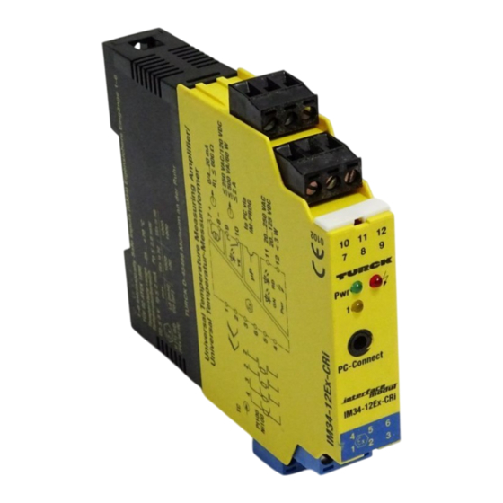
LED-Anzeigen (Fig. 1)
Pwr
grün
Betriebsbereitschaft
ó
rot
Fehler
1
gelb
Relais angezogen (nur IM34-12Ex-CRi)
Hinweis: Statusanzeigen, siehe Tab. 1 auf nächster Seite
1 / 12
, 2 × 1,5 mm
oder 2 × mm
mit Ader-
2
2
2
Temperature measuring amplifier
IM34-11-Ci
IM34-11Ex-Ci
IM34-11Ex-Ci/K51
IM34-11Ex-Ci/K60
IM34-12Ex-CRi
Short description
•
Inputs for Ni100 or Pt100 acc. to IEC 751, thermoelements acc. to IEC 584
and for low voltages (mV range)
•
Only on devices with "Ex" in the type designation:
– Intrinsically safe input circuit Ex ia
– Area of application acc. to ATEX: II (1) G, II (1) D, II 3 G
– Approved for installation in zone 2
•
Wire-break monitoring
•
Short-circuit monitoring only of Pt100 or Ni100 components
•
Thermoelement measuring with external and internal cold junction
compensation
•
Galvanic isolation between input and output circuits and supply
•
Analog current output 0/4...20 mA
•
Voltage proof up to 4 kV (IM34-11Ex-Ci/K51 only)
•
Fast temperature measurement from a temperature gradient of 200 µV/s
(IM34-11Ex-Ci/K60 only)
•
Limit value relay (IM34-12Ex-CRi only)
•
Temperature linear conversion
•
Parametrized via PC and programming adapter IM-PROG III
(to be ordered additionally – ident-no.: 7525111)
•
Housing with coded and removeable terminal blocks
•
Simulation of outputs
•
Universal operating voltage
– 20...250 VAC/20...125 VDC
– 20...250 VUC (only IM34-11-Ci)
Terminal configuration (Fig. 2)
1, 2
Thermoelement and mV input
3 – 6 Ni100 or Pt100 input
7, 8
Analog current output (0/4...20 mA)
9, 10 Limit value relay (IM34-12Ex-CRi only)
11, 12 Supply voltage connection
Connection via lifting cages with captive screws, connection profile:
≤ 1 × 2.5 mm
, 2 × 1.5 mm
or 2 × 1 mm
2
2
torque: 0.5 Nm
LED indications (Fig. 1)
Pwr
green
power on
ó
red
error
1
yellow
relay energized (IM34-12Ex-CRi only)
Note: Status indications, see table 1 on the next page
with wire sleeves, max. tightening
2

Verwandte Anleitungen für turck IM34-11-Ci


Inhaltszusammenfassung für turck IM34-11-Ci
- Seite 1 Universal operating voltage • Universelle Betriebsspannung – 20…250 VAC/20…125 VDC – 20…250 VAC/20…125 VDC – 20…250 VUC (only IM34-11-Ci) – 20…250 VUC (nur bei IM34-11-Ci) Klemmenbelegung (Fig. 2) Terminal configuration (Fig. 2) 1, 2 Thermoelement- und mV-Eingang 1, 2 Thermoelement and mV input 3 –...
- Seite 2 IM34-11-Ci/IM34-11Ex-Ci... /IM34-12Ex-CRi Fig. 1 Fig. 2 IM34-11...-Ci... to PC via µP IM-PROG – 2 0/4...20 mA 8 – R L £ 600 W Power *) Nur bei Geräten mit „Ex“ in der Typenbezeichnung/ Only on devices with “Ex” in the type designation...
- Seite 3 Dokumentation „Software-Installation PACTware™ und Geräte-DTMs“, software installation”, D201354). D201354). The TURCK adapter IM-PROG III is needed to establish the connection bet- Der TURCK-Adapter IM-PROG III dient zur Verbindung zwischen dem Gerät ween the device and your PC. und Ihrem PC. Verbinden Sie dazu den 3,5-mm-Stecker mit dem Messver- For this it is necessary to connect the 3.5 mm connector to the measuring...
- Seite 4 IM34-11-Ci/IM34-11Ex-Ci... /IM34-12Ex-CRi Montage und Installation (Fig. 3) Mounting and installation (Fig. 3) Die angeschlossenen Betriebsmittel (Ni100/Pt100, Thermoelement) müssen The connected apparatus (Ni100/Pt100, thermoelement) must meet the die Voraussetzung zum Einsatz im explosionsgefährdeten Bereich erfüllen requirements for use in explosion hazardous areas (EN 60079-14).
- Seite 5 The most important data from the EC type examination certificate are gungen der TURCK-Geräte finden Sie im Internet (www.turck.com). listed overleaf. All valid national and international approvals covering Turck Die Besonderen Bedingungen IECEx CoC sind unter www.iecex.com zu devices are obtainable via the Internet (www.turck.com). The special condi- tions of IECEx CoC can be accessed on www.iecex.com.
- Seite 6 Обращать внимание на особые указания! Все национальные tarse vía Internet. и международные сертификаты доступны через Интернет. Internet: www.turck.com → www.turck.de Technische Daten/Vorgaben durch die ATEX-Zulassung Technical Data/In Accordance with ATEX Specifications ............................≤ 5 V ............................
- Seite 7 Tension de service universelle – 20...250 VAC/20...125 VDC – 20...250 VAC/20...125 VDC – 20...250 VUC (apenas IM34-11-Ci) – 20...250 VUC (uniquement IM34-11-Ci) Raccordement des bornes (Fig. 2) Configuração dos terminais (Fig. 2) 1, 2 Entrée pour thermocouple et mV 1, 2 Termoelemento e entrada mV 3 –...
- Seite 8 IM34-11-Ci/IM34-11Ex-Ci... /IM34-12Ex-CRi Fig. 1 Fig. 2 IM34-11...-Ci... to PC via µP IM-PROG – 2 0/4...20 mA 8 – R L £ 600 W Power *) Uniquement pour les appareils où „Ex“ figure dans la désignation de type/ Apenas para dispositivos com designação do tipo "Ex"...
- Seite 9 DTM d‘appareils“, D201354). (ver também “PACTware™ and devices DTM software installation”, D201354). Le IM-PROG III de TURCK sert à connecter l'appareil à votre PC. O adaptador TURCK IM-PROG III é necessário para estabilizar a conexão entre Branchez le connecteur 3,5 mm sur l‘amplificateur de mesure (PC-Connect) o equipamento e seu PC.
- Seite 10 IM34-11-Ci/IM34-11Ex-Ci... /IM34-12Ex-CRi Montage et installation (Fig. 3) Montagem e instalação (Fig. 3) Les matériels électriques (Ni100/Pt100, thermocouple) raccordés doivent O instrumento conectado (Ni100/Pt100, termoelementos) deve atender remplir les exigences pour le fonctionnement dans la zone explosible os requisitos para uso em áreas com risco de explosão (EN/ABNT NBR IEC (EN 60079-14).
- Seite 11 Les données essentielles de l‘attestation d‘examen CE figurent au verso. Os dados mais importantes do certificado de exame do tipo EC estão L‘ensemble des certificats nationaux et internationaux des appareils TURCK listados no verso. Todas as aprovações nacionais e internacionais válidas peuvent être obtenus par internet (www.turck.com).
- Seite 12 Nr./No..TÜV 02 ATEX 1898/TÜV 06 ATEX 552978 X/TUN 06.0010X Irrtümer und Änderungen vorbehalten / Subject to change without notice / Sous réserve de modifications / Sujeito a alterações sem prévio aviso • © Hans Turck GmbH & Co. KG 2014...