Werbung
Quicklinks
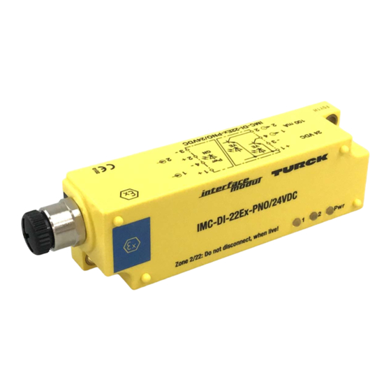
IMC-DI-22Ex-PN.../24VDC
M12 x 1
Power
2
Switching status
LED
M12 x 1
91,5
100
125
23,5
8
Wiring Diagram
BN
1 +
+ 1
1
1
Pwr
BU
24 VDC
YE/RD
– 4
3 –
GN
NAMUR
2
BN
YE/RD
+ 2
2
2
2
BU
100 mA
– 3
4
1
NAMUR
2
2
1
3
3
5
4
4
Pin assignment female M12
Pin assignment male M12
(intrinsically safe end)
DE
Kurzbetriebsanleitung
IMC-DI-22Ex-PN.../24VDC
Weitere Unterlagen
32
Ergänzend zu diesem Dokument finden Sie im Internet unter
Unterlagen:
25
■
Datenblatt
■
Zulassungen
■
EU-Konformitätserklärung (aktuelle Version)
Zu Ihrer Sicherheit
Bestimmungsgemäße Verwendung
Die Geräte sind nur zum Einsatz im industriellen Bereich bestimmt.
Die Trennschaltverstärker IMC-DI-22Ex-PN.../24VDC sind mit eigensicheren Eingangskreisen
ausgestattet und übertragen binäre Signale aus dem explosionsgefährdeten Bereich in den
sicheren Bereich. Die Geräte sind auch für den Betrieb in Zone 2 und Zone 22 geeignet. An die
Geräte können Sensoren nach EN 60947-5-6 (NAMUR), variable Widerstände oder potenzial-
freie Kontaktgeber angeschlossen werden. Mit den Geräten lassen sich auch sicherheitsge-
richtete Anwendungen bis einschließlich SIL2 (Low-Demand gemäß IEC 61508) aufbauen
(Hardwarefehlertoleranz HFT = 0).
Die Geräte dürfen nur wie in dieser Anleitung beschrieben verwendet werden. Jede andere
Verwendung gilt als nicht bestimmungsgemäß. Für daraus resultierende Schäden übernimmt
Turck keine Haftung.
Allgemeine Sicherheitshinweise
■
Nur fachlich geschultes Personal darf das Gerät montieren, installieren, betreiben, paramet-
rieren und instand halten.
■
Die Geräte erfüllen ausschließlich die EMV-Anforderungen für den industriellen Bereich und
sind nicht zum Einsatz in Wohngebieten geeignet.
■
Die Schutzart IP67 ist nur gewährleistet, wenn die Steckverbinder verschraubt sind.
Hinweise zum Ex-Schutz
■
Nationale und internationale Vorschriften für den Explosionsschutz beachten.
■
Bei Einsatz des Gerätes in Ex-Kreisen muss der Anwender über Kenntnisse im Explosions-
schutz (EN 60079-14 etc.) verfügen.
■
Das Gerät nur innerhalb der zulässigen Betriebs- und Umgebungsbedingungen (siehe
Zulassungsdaten und Auflagen durch die Ex-Zulassung) einsetzen.
Auflagen durch die ATEX- und IECEx-Zulassung bei Einsatz in Zone 2 und Zone 22
■
Nicht eigensichere Stromkreise nur trennen und verbinden, wenn keine Spannung anliegt.
1
■
Gerät mit der Metallabdeckung IMC-SG gegen mechanische Beschädigungen schützen.
■
Gerät gegen ultraviolettes Licht schützen.
■
5
In Anwendungen, die einen EPL Dc erfordern: Der Wert der Oberflächentemperatur wurde
ohne Staubauflage gemessen.
■
In Anwendungen, die einen EPL Dc erfordern: Der Staub darf nur nichtleitfähig sein.
■
In Anwendungen, die einen EPL Dc erfordern: Gerät vor elektrostatischer Aufladung schüt-
zen.
Produktbeschreibung
Geräteübersicht
siehe Abb. 1: Frontansicht, Abb. 2: Abmessungen
Funktionen und Betriebsarten
Die Trennschaltverstärker IMC-DI-22Ex-PN.../24VDC sind mit zwei Transistorausgängen ausge-
stattet und übertragen die Eingangssignale der Sensoren, der variablen Widerstände oder der
potenzialfreien Kontakte aus dem explosionsgefährdeten Bereich in den sicheren Bereich. Die
Transistorausgänge sind als Öffner (IMC-DI-22Ex-PNC...) oder Schließer (IMC-DI-22Ex-PNO...)
ausgeführt. In Abhängigkeit vom jeweiligen Eingangspegel werden die Eingangssignale als
Low- oder High-Pegel interpretiert und als ein entsprechendes Ausgangssignal zur Verfügung
gestellt. Das Gerät benötigt eine Spannungsversorgung von 24 VDC.
Montieren
GEFAHR
Explosionsfähige Atmosphäre
Explosion durch zündfähige Funken!
Bei Einsatz in Zone 2 und Zone 22:
Gerät nur montieren und anschließen, wenn keine explosionsfähige Atmosphäre
➤
vorliegt.
Gerät mit der Metallabdeckung IMC-SG (Ident-No. 7560016) gegen mechanische Beschä-
➤
digungen schützen.
Steckverbinder im Ex-Bereich mit O-Ringdichtungen aus NBR80, FPM80 oder NBR70
➤
versehen.
Gerät mit zwei M4-Schrauben auf einer Montageplatte befestigen. Zur Befestigung keine
➤
Blechschrauben oder Holzschrauben verwenden. Das max. Anziehdrehmoment für die
Schrauben beträgt 2,2 Nm.
Gerät vor Wärmestrahlung, schnellen Temperaturschwankungen, starker Verschmutzung,
➤
elektrostatischer Aufladung und mechanischer Beschädigung schützen.
Anschließen
Gerät gemäß „Wiring Diagram" anschließen. Das max. Anziehdrehmoment für die M12-
➤
Steckverbinder beträgt 3,5 Nm.
Steckverbinder im Ex-Bereich mit O-Ringdichtungen aus NBR80, FPM80 oder NBR70 verse-
➤
hen.
FR
Guide d'utilisation rapide
IMC-DI-22Ex-PN.../24VDC
Documents complémentaires
www.turck.com
folgende
Vous trouverez les documents suivants contenant des informations complémentaires à la
présente notice sur notre site Web www.turck.com :
■
Fiche technique
■
Homologations
■
Déclaration de conformité UE (version actuelle)
Pour votre sécurité
Utilisation correcte
Les appareils sont conçus uniquement pour une utilisation dans le domaine industriel.
Les amplificateurs-séparateurs de commutation IMC-DI-22Ex-PN.../24VDC sont équipés de
circuits d'entrée à sécurité intrinsèque et transmettent les signaux binaires depuis la zone pré-
sentant un risque d'explosion jusqu'à la zone sécurisée. Par ailleurs, les appareils sont adaptés
à un fonctionnement en zone 2 et en zone 22. Des détecteurs suivant EN 60947-5-6 (NAMUR),
des résistances variables ou des contacteurs libres de potentiel peuvent être raccordés aux
appareils. Les appareils permettent également de mettre en place des applications de sécurité,
notamment des applications SIL2 (Low Demand selon CEI 61508 ; tolérance aux pannes maté-
rielles HFT = 0).
Les appareils doivent exclusivement être utilisés conformément aux indications figurant dans
la présente notice. Toute autre utilisation est considérée comme non conforme. La société Turck
décline toute responsabilité en cas de dommages causés par une utilisation non conforme.
Consignes de sécurité générales
■
Seul un personnel qualifié est habilité à monter, installer, utiliser, paramétrer et effectuer la
maintenance de l'appareil.
■
Les appareils répondent exclusivement aux exigences de la directive CEM pour le secteur
industriel et ne sont pas destinés à être utilisés dans les zones d'habitation.
■
Le mode de protection IP67 n'est garanti que si les connecteurs sont vissés.
Indications relatives à la protection contre les explosions
■
Respectez les consignes nationales et internationales relatives à la protection contre les
explosions.
■
En cas d'utilisation de l'appareil dans des zones à risque d'explosion, vous devez en outre
disposer des connaissances requises en matière de protection contre les explosions
(EN 60079-14, etc.).
■
Utilisez uniquement l'appareil dans le respect le plus strict des conditions ambiantes et des
conditions d'exploitation autorisées (voir données de certification et consignes relatives à
l'homologation Ex).
Exigences de l'homologation ATEX et IECEx pour une utilisation en zone 2 et en zone 22
■
Les circuits à sécurité électrique non intrinsèque doivent être séparés et raccordés unique-
ment lorsqu'aucune tension n'est présente.
■
Protégez l'appareil de tout dommage mécanique avec la plaque de recouvrement métal-
lique IMC-SG.
■
Protégez l'appareil des ultraviolets.
■
Dans les applications nécessitant un EPL Dc : La température de surface a été mesurée sans
dépôt de poussière.
■
Dans les applications nécessitant un EPL Dc : La poussière ne peut pas être conductible.
■
Dans les applications nécessitant un EPL Dc : Protégez l'appareil des charges électrosta-
tiques.
Description du produit
Aperçu de l'appareil
voir Fig. 1 : vue de face, Fig. 2 : Dimensions
Fonctions et modes de fonctionnement
Les amplificateurs-séparateurs de commutation IMC-DI-22Ex-PN.../24VDC sont équipés de
deux sorties transistor et transmettent les signaux d'entrée des capteurs, des contacteurs libres
ou des contacts libres de potentiel depuis la zone présentant un risque d'explosion à la zone
sécurisée. Les sorties transistor sont conçues comme des contacts à ouverture (IMC-DI-22Ex-
PNC...) ou à fermeture (IMC-DI-22Ex-PNO...). En fonction des niveaux d'entrée respectifs, les
signaux d'entrée sont interprétés avec un niveau bas ou élevé et présentés comme un signal de
sortie correspondant. L'appareil a besoin d'une alimentation en tension de 24 VDC.
Montage
DANGER
Atmosphère présentant un risque d'explosion
Explosion par étincelles inflammables !
Utilisation en zone 2 et en zone 22 :
Veuillez uniquement effectuer les travaux de montage et de raccordement après avoir
➤
vérifié que l'atmosphère ne présente pas de risque d'explosion.
Protégez l'appareil de tout dommage mécanique avec la plaque de recouvrement métal-
➤
lique IMC-SG (n° d'identification 7560016).
Appliquez des joints toriques en NBR80, FPM80 ou NBR70 sur les connecteurs dans la
➤
zone Ex.
Fixez l'appareil sur une plaque de montage à l'aide de deux vis M4. Ne pas utiliser de vis à
➤
tôle ou de vis à bois. Le couple de serrage maximal des vis est de 2,2 Nm.
Protégez l'appareil contre les rayonnements thermiques, les variations rapides de tem-
➤
pérature, le fort encrassement, les charges électrostatiques et tout endommagement
mécanique.
EN
Quick-Start Guide
IMC-DI-22Ex-PN.../24VDC
Other documents
Besides this document, the following material can be found on the Internet at www.turck.com:
■
Data sheet
■
Approvals
■
EU declaration of conformity (current version)
For your safety
Intended use
The devices are designed only for use in industrial areas.
The IMC-DI-22Ex-PN.../24VDC isolating switching amplifiers are equipped with intrinsically safe
input circuits and transfer binary signals from the Ex area to the safe area. The devices are also
suitable for use in Zone 2 and Zone 22. Sensors according to EN 60947‐5‐6 (NAMUR), variable
resistors or potential-free contacts can be connected to the devices. The devices also enable
the creation of safety-related applications up to and including SIL2 (low demand in accordance
with IEC 61508; hardware fault tolerance HFT = 0).
The devices must only be used as described in these instructions. Any other use is not in ac-
cordance with the intended use. Turck accepts no liability for any resulting damage.
General safety instructions
■
The device must only be mounted, installed, operated, parameterized and maintained by
trained and qualified personnel.
■
The devices only meet the EMC requirements for industrial areas and are not suitable for use
in residential areas.
■
Protection type IP67 is only guaranteed if the connectors are screw fastened.
Notes on Ex protection
■
Observe national and international regulations for explosion protection.
■
When using the device in Ex circuits, the user must also have an additional knowledge of
explosion protection (EN 60079-14 etc.).
■
Only use the device within the permissible operating and ambient conditions (see certifica-
tion data and Ex approval specifications).
Requirements from the ATEX and IECEx approval for use in Zone 2 and Zone 22
■
Only disconnect and connect non-intrinsically safe electrical circuits if no voltage is applied.
■
Protect the device from mechanical damage with the IMC-SG metal cover.
■
Protect the device from ultraviolet light.
■
In applications requiring an EPL Dc: The value of the surface temperature was measured
without any dust deposit.
■
In applications requiring an EPL Dc: The dust must only be non-conductive.
■
In applications requiring an EPL Dc: Protect the device from electrostatic charge.
Product description
Device overview
See Fig. 1: Front view, Fig. 2: Dimensions
Functions and operating modes
The IMC-DI-22Ex-PN.../24VDC isolating switching amplifiers are equipped with two transistor
outputs and transfer the input signals of the sensors, the variable resistors or the potential-free
contacts from the Ex area to the safe area. The transistor outputs are designed as NC contacts
(IMC-DI-22Ex-PNC...) or NO contacts (IMC-DI-22Ex-PNO...). The input signals are interpreted
as low or high signals depending on the input level, and provided as a corresponding output
signal. The device is designed for a 24 VDC power supply.
Installing
DANGER
Potentially explosive atmosphere
Risk of explosion due to spark ignition!
Use of devices in Zone 2 and Zone 22:
Mounting and connection are only permissible if there is no potentially explosive atmo-
➤
sphere present.
Protect the device from mechanical damage with the IMC-SG metal cover (Ident no.
➤
7560016).
Provide connectors in the Ex area with O ring seals made from NBR80, FPM80 or NBR70.
➤
Fasten the device on a mounting plate with two M4 screws. Do not use any metal or wood
➤
screws for fastening. The maximum tightening torque for the screws is 2.2 Nm.
Protect the device from heat radiation, rapid temperature fluctuations, severe contamina-
➤
tion, electrostatic charge and mechanical damage.
Connection
Connect the device according to the "Wiring diagram". The maximum tightening torque for
➤
the M12 connectors is 3.5 Nm.
Provide connectors in the Ex area with O ring seals made from NBR80, FPM80 or NBR70.
➤
© Hans Turck GmbH & Co. KG | D201294 2020-06 | V2.0
Werbung

Verwandte Anleitungen für turck IMC-DI-22Ex-PN Serie


Inhaltszusammenfassung für turck IMC-DI-22Ex-PN Serie
- Seite 1 Ergänzend zu diesem Dokument finden Sie im Internet unter www.turck.com folgende Vous trouverez les documents suivants contenant des informations complémentaires à la Besides this document, the following material can be found on the Internet at www.turck.com: ■ présente notice sur notre site Web www.turck.com : Unterlagen:...
- Seite 2 : -25…+70 °C Hans Turck GmbH & Co. KG | Witzlebenstr. 7, 45472 Mülheim an der Ruhr, Germany | Tel. +49 208 4952-0 | Fax +49 208 4952-264 | more@turck.com | www.turck.com © Hans Turck GmbH & Co. KG | D201294 2020-06 | V2.0...
-
Seite 3: Installazione
Los dispositivos solo se deben usar como se describe en estas instrucciones. Ninguna otra forma de uso corresponde al uso previsto. Turck no se responsabiliza de los daños derivados de Notas de segurança gerais Indicazioni generali di sicurezza dichos usos. - Seite 4 : -25…+70 °C Hans Turck GmbH & Co. KG | Witzlebenstr. 7, 45472 Mülheim an der Ruhr, Germany | Tel. +49 208 4952-0 | Fax +49 208 4952-264 | more@turck.com | www.turck.com © Hans Turck GmbH & Co. KG | D201294 2020-06 | V2.0...
- Seite 5 другое использование не признается использованием по назначению. Turck не несет Urządzenia powinny być używane wyłącznie w sposób opisany w określonych instrukcjach. ответственности за возможные повреждения. Każde inne wykorzystanie jest uznawane za niezgodne z przeznaczeniem. Firma Turck nie Všeobecné bezpečnostní informace ■...
- Seite 6 : -25…+70 °C Hans Turck GmbH & Co. KG | Witzlebenstr. 7, 45472 Mülheim an der Ruhr, Germany | Tel. +49 208 4952-0 | Fax +49 208 4952-264 | more@turck.com | www.turck.com © Hans Turck GmbH & Co. KG | D201294 2020-06 | V2.0...
- Seite 7 「配線図」 にしたがってデバイスを接続します。 M12コネクタの最大締め付け トルクは3.5 Nm 연결 ➤ です。 防爆エリアのコネクタにNBR80、 FPM80、 またはNBR70製のOリングシールを取り付けま „배선도“에 따라 장치를 연결하십시오. M12 커넥터의 최대 조임 토크는 3.5 Nm입니다. ➤ す。 ➤ 폭발 위험 구역에 NBR80, FPM80 또는 NBR70으로 만든 O링 씰이 장착된 커넥터를 제 ➤ 공하십시오. © Hans Turck GmbH & Co. KG | D201294 2020-06 | V2.0...
- Seite 8 : -25…+70 °C Hans Turck GmbH & Co. KG | Witzlebenstr. 7, 45472 Mülheim an der Ruhr, Germany | Tel. +49 208 4952-0 | Fax +49 208 4952-264 | more@turck.com | www.turck.com © Hans Turck GmbH & Co. KG | D201294 2020-06 | V2.0...