Werbung
Quicklinks
Temperaturmessverstärker
IME-TI-11Ex-Ci/24VDC
Gerätekurzbeschreibung
•
Einkanaliger Temperaturmessverstärker
• Eigensicherer Eingangskreis Ex ia zum Anschluss von Pt100 and Ni100
Temperaturwiderständen (RTDs), Thermoelementen, Widerständen
und Potentiometer und Kleinspannungen (mV-Bereich)
•
Anschluss von RTDs in 2-, 3- oder 4-Draht-Technik
•
Thermoelentmessung mit externer, interner und konstanter Kaltstellen-
kompensation
•
Drahtbruchüberwachung
•
Kurzschlussüberwachung nur von Pt100- oder Ni100-RTDs
•
Ausgangskreis 0/4...20 mA, kurzschlussfest
•
Galvanische Trennung zwischen Eingangskreis und Ausgangskreis und
zur Versorgung
•
Anwendungsbereich nach ATEX: II (1) GD, II 3 G
•
Zugelassen für Einbau in Zone 2
•
Parametrierung über PC mit dem Programmieradapter IM-PROG III
(optional bei TURCK verfügbar, Ident-Nr.: 6890422)
•
Simulation der Ausgänge
Klemmenbelegung (Fig. 2)
1, 2
Thermoelement und mV-Eingang
3 – 6
RTD-, Widerstand- und Potentiometer-Eingang
9, 10
Analoger Stromausgang (0/4...20 mA)
14, 13
Betriebsspannung
12, 11
Betriebsspannung durchgeschliffen
Anschluss über Federzugklemmen:
Anschlussquerschnitt 0,75 mm
...1,5 mm
2
Endhülsen.
LED-Anzeigen (Fig. 1 + 2)
Pwr
grün
Betriebsbereitschaft
ó
rot
Fehler
Hinweis: Statusanzeigen, siehe Tabelle 1 auf Seite 2
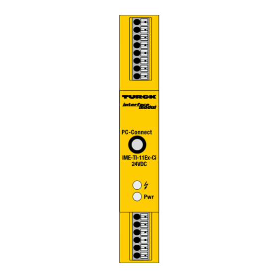
Fig. 1 Frontansicht
Front view
IME-TI-11Ex-Ci
24VDC
Pwr
oder 0,5 mm
...1 mm
mit Ader-
2
2
2
Temperature measuring amplifier
IME-TI-11Ex-Ci/24VDC
Short description
• Single-channel temperature measuring amplifier
• Intrinsically safe input circuit Ex ia for connection of Pt100 and Ni100
resistance temperature detectors (RTDs), thermoelements, resistors
and potentiometers and low voltages (mV range)
• Connection of RTDs with 2-, 3- or 4-wire technology
• Thermoelement measuring with external, internal and constant cold
junction compensation
• Wire-break monitoring
• Short-circuit monitoring only of Pt100 or Ni100 RTDs
• Output circuit 0/4...20 mA, short-circuit protected
• Galvanic isolation between input and output circuits and power supply
• Application area according to ATEX: II (1) GD, II 3 G
• Approved for installation in zone 2
• Parameterization via PC via programming adapter IM-PROG III
(optionally available from TURCK, ident-no.: 6890422)
• Simulation of outputs
Terminal configuration (Fig. 2)
1, 2
Thermoelement and mV input
3 – 6
RTD, resistor and potentiometer input
9, 10
Analog current output (0/4...20 mA)
14, 13
Power supply
12, 11
Power supply looped in
Connection via cage-clamp terminals:
Connection profile 0.75 mm
...1.5 mm
2
sleeves.
LED indications (Fig. 1 + 2)
Pwr
green
Power on
ó
red
Error
Note: Status indications, see table 1 on page 2
Fig. 2
Blockschaltbild
Circuit diagram
+ 1
mV
TC
– 2
3
4
3
2
6
%
5
ò/RTD
4
3
or 0.5 mm
...1 mm
with wire
2
2
2
to PC via
µP
IM-PROG
10 +
0/4...20 mA
9 –
R L £ 600 W
12, 14 +
GN
RD
24 VDC
11, 13 –
Pwr
Werbung

Verwandte Anleitungen für turck IME-TI-11Ex-Ci/24VDC


Inhaltszusammenfassung für turck IME-TI-11Ex-Ci/24VDC
- Seite 1 • Parameterization via PC via programming adapter IM-PROG III Zugelassen für Einbau in Zone 2 • Parametrierung über PC mit dem Programmieradapter IM-PROG III (optionally available from TURCK, ident-no.: 6890422) • Simulation of outputs (optional bei TURCK verfügbar, Ident-Nr.: 6890422) •...
- Seite 2 Installation PACTware™ und Geräte-DTMs“, D201354). D201354). Der TURCK-Adapter IM-PROG III dient zur Verbindung zwischen dem Gerät Use the TURCK adapter IM-PROG III to establish the connection between the und Ihrem PC. device and your PC. Verbinden Sie dazu den 3,5-mm-Stecker mit dem Messverstärker (PC-Con- Plug the 3.5 mm connector to the measuring amplifier (PC-Connect) and the...
- Seite 3 IME-TI-11Ex-Ci/24VDC Besondere Bedingungen für den Einsatz in Zone 2 Special conditions for application in zone 2 Bei Einbau in Zone 2 muss das Gerät in ein Gehäuse nach EN 60079-15 mit For installation in zone 2 the device must be installed in a housing which einer Schutzart mindestens IP54 nach IEC/EN 60529 montiert werden.
- Seite 4 IME-TI-11Ex-Ci/24VDC 1012...
- Seite 5 Alle gültigen nationalen und internationalen Bescheini- TURCK devices are obtainable via the Internet (www.turck.com). gungen der TURCK-Geräte finden Sie im Internet (www.turck.com). Weitere Informationen zum Ex-Schutz stellen wir Ihnen auf Anfrage gern zur Verfügung. Further information on explosion protection is available on request.
-
Seite 6: Konformitätserklärung
Irrtümer und Änderungen vorbehalten / Subject to change without notice • © Hans Turck GmbH & Co. KG 2012 Hans Turck GmbH & Co. KG • Witzlebenstraße 7 • 45472 Mülheim/Ruhr • Germany • Tel. +49 (0) 208/4952-0 • Fax +49 (0) 208/4952-264 • more@turck.com • www.turck.com...