Herunterladen Inhalt Inhalt Diese Seite drucken
Carrier 39CQ Anleitung
Vorschau ausblenden Andere Handbücher für 39CQ:
Inhaltsverzeichnis

Werbung

Verfügbare Sprachen

Verfügbare Sprachen

INSTALLATION, OPERATION AND
M A I N T E N A N C E I N S T R U C T I O N S
Air Handling Unit
39CQ
Air flow: to 6000 m
3
/h
Original document

Werbung

Inhaltsverzeichnis
loading

Inhaltszusammenfassung für Carrier 39CQ

  • Seite 1 INSTALLATION, OPERATION AND M A I N T E N A N C E I N S T R U C T I O N S Air Handling Unit 39CQ Air flow: to 6000 m Original document...
  • Seite 3: Inhaltsverzeichnis

    SOMMAIRE PAGE 1 - RECEPTION DE L'APPAREIL 1.1 Livraison / Réserves 1.2 Précautions de stockage 1.3 Emballage 1.4 Manutention 2 - CONSIGNES DE SECURITE 2.1 Consignes de sécurité générales 2.2 Domaine d'application 3 - DESCRIPTIF DE L'APPAREIL 3.1 Plaque signalétique firme 3.2 Pictogrammes 4 - INSTALLATION ET RACCORDEMENTS INSTALLATION 4.1 Choix de l'emplacement...
  • Seite 4: Reception De L'appareil

    Pour votre sécurité, pensez à vous équiper des différents EPI 1 - RECEPTION DE L'APPAREIL L’installation et les opérations de maintenance doivent être réalisées par des personnes qualifiées et expérimentées. Lors de chaque intervention, observer scrupuleusement les précautions d’utilisation. Des étiquettes sont apposées sur l’appareil afin de rappeler les consignes de sécurité.
  • Seite 5: Descriptif De L'appareil

    3 - DESCRIPTIF DE L'APPAREIL 3.1 Plaque signalétique firme Elle est fixée sur la centrale et mentionne les caractéristiques de la centrale avec le N° de commande et le repère. 3.2 Pictogrammes Côté raccordement (orientation droite) : 1 – Sécurité filtre 2 –...
  • Seite 6: Installation Et Raccordements Installation

    4 - INSTALLATION ET RACCORDEMENTS INSTALLATION L’installation des équipements doit être conforme à la réglementation en vigueur dans le pays de destination. 4.1 Choix de l'emplacement Horizontal en plafonnier Vertical Horizontal au sol Suivant le type de l’appareil commandé, il peut être installé en plafonnier, au sol ou vertical. Prévoir un espace minimum pour l’ouverture des portes (540 mm, 595 mm, 735 mm suivant la configuration).
  • Seite 7 Fixation sur leur support : Lg module cache plastique plot d'amortissement platine vis H6 ∅ 8 x 80 Assemblage entre caissons (pour CTA multi-blocs) : - Coller le joint PVC 25 x 5 sur la face de raccordement du caisson additionnel - Placer les tiges filetées dans les platines - Serrer le caisson additionnel sur le caisson principal à...
  • Seite 8: Raccordement Aéraulique

    4.3 Raccordement aéraulique Aucun raccordement ne doit exercer de contraintes mécaniques sur la centrale Utiliser des manchettes souples à l’aspiration et au refoulement Aspiration ou refoulement : Taille ∅ 4.2 1310 1254 212.3 1880 1824 230.5 C x D Caisson de mélange : 2 voies 3 voies ∅...
  • Seite 9: Servomoteurs

    Schéma de principe du siphon : Pour une dépression H au niveau de la batterie froide, le siphon doit respecter les côtes de 2H dans son dimensionnement. Bac de récupération en dépression Hmm CE Légère pente 5/1000 Vers égout 4.5 Servomoteurs Couple de fermeture des registres : Centrale de traitement d'air Taille 025...
  • Seite 10 Réglage usine Réglage 1 : Réglage 2 : Réglage 3 : Description Vitesse par Vitesse par contact Vitesse au clavier potentiomètre Paramètres de niveau 1 Vitesse minimum (Hz) Vitesse maximum (Hz) Moteur 0.55 kW : 97 , Moteur 1.1 kW : 60 , Moteur 1.4 kW : 65 Rampe d'accélération (s / 100 Hz) Rampe de décélération (s / 100 Hz) Configuration du variateur...
  • Seite 11: Batterie Électrique

    Réglage usine Réglage 1 : Réglage 2 : Réglage 3 : Description Vitesse par Vitesse par contact Vitesse au clavier potentiomètre Paramètres de niveau 3 Mise en sécurité précédant celle du Pr 55 Mise en sécurité précédant celle du Pr 56 Mise en sécurité...
  • Seite 12 Puissance (kW) Nombres d'allures Puissance (kW) Nombre d'allures Option A Taille 025 Taille 040 Taille 060 Avec coffret électrique : TOR ou TRIAC : Coffret non disponible pour l’option A. Options coffret : o Option B : TOR (2 étages) / monté et câblé o Option C : TOR (2 étages) / coffret non monté...
  • Seite 13: Mise En Service

    5 - MISE EN SERVICE La mise en service doit être faite par un personnel qualifié, formé aux techniques du traitement d’air. Aucune porte de visite ne doit être ouverte pendant le fonctionnement de la centrale. Une fois les opérations de raccordements électriques, hydrauliques et aérauliques effectuées, procéder à la mise en service de la centrale en contrôlant les points suivants : •...
  • Seite 14 Groupes moto-ventilateurs : - Contrôler la tension d’alimentation électrique ainsi que le calibrage des protections thermiques par rapport aux intensités des différents éléments - Vérifier que la masse est raccordée et que la roue tourne librement - Vérifier le débit d’air et la pression disponible Calcul du débit d’air : Roue libre avec moteur asynchrone Roue libre avec moteur EC...
  • Seite 15: Maintenance / Periodicite Des Interventions

    6 - MAINTENANCE / PERIODICITE DES INTERVENTIONS Couper l’alimentation électrique de la centrale de traitement d'air avant toutes interventions L’entretien doit être fait par des personnes qualifiées Arrêter la machine via l’interface homme machine puis couper l'alimentation électrique (respecter les durées de post- ventilation) Il est possible de démonter les portes afin de faciliter l'accès aux différents composants grâce aux charnières dégondables.
  • Seite 17 CONTENTS PAGE 1 - RECEIPT OF THE UNIT 1.1 Delivery/Reservations 1.2 Storage precautions 1.3 Packaging 1.4 Handling 2 – SAFETY INSTRUCTIONS 2.1 General safety instructions 2.2 Field of application 3 - DESCRIPTION OF THE UNIT 3.1 Fixed name plate 3.2 Pictograms 4 –...
  • Seite 18: Receipt Of The Unit

    These comments must be confirmed to the carrier by registered letter within two business days, and a copy of this letter must be sent to the manufacturer.
  • Seite 19: Description Of The Unit

    3 - DESCRIPTION OF THE UNIT 3.1 Fixed name plate This is fixed on the unit and shows the unit's specifications as well as the order number and code. (Order number) (CUSTOMER REF:) 3.2 Pictograms Connection side (right-hand orientation): 1 – Filter safety device 2 –...
  • Seite 20: Installation And Connections Installation

    4 – INSTALLATION AND CONNECTIONS INSTALLATION The installation of the equipment must comply with the regulations and standards of the recipient country. 4.1 Selecting a location Horizontal ceiling-mounted Vertical Horizontal floor-mounted Depending on the type of unit being controlled, it can either be ceiling- or floor-mounted or installed vertically. Ensure a minimum space is left to allow the doors to open (540mm, 595mm, 735mm depending on the configuration).
  • Seite 21 Mounting to their support: Module length plastic cover anti-vibration mount plate H6 ∅ 8 x 80 screws Assembling the casings (for multi-unit AHUs): - Bond the PVC 25 x 5 gasket to the connection face of the additional casing - Fit the threaded rods in the plates - Secure the additional casing to the main casing using the nuts provided (the casings must be perfectly aligned to ensure the tightness of the assembly) plate...
  • Seite 22: Air Connection

    4.3 Air connection Connections must not place mechanical stresses on the unit Use the flexible sleeves for the intake and discharge Intake or discharge: Size ∅ 4.2 1310 1254 212.3 1880 1824 230.5 C x D Mixing box: 2-way 3-way ∅...
  • Seite 23: Servomotors

    Schematic diagram of the siphon: For a depression H in the cooling coil, the sizing of the siphon must incorporate dimensions of 2H. Negative-pressure recovery pan Bac de récupération en dépression HmmWC Hmm CE Slight slope of 0.005 Légère pente 5/1000 To sewer system Vers égout 4.5 Servomotors...
  • Seite 24 Factory setting Setting 1: Setting 2: Setting 3: Description Speed from Speed from Speed on the potentiometer contact keypad Level 1 parameters Minimum speed (Hz) Maximum speed (Hz) 0.55 kW motor: 97 , 1.1 kW motor: 60 , 1.4 kW motor: 65 Acceleration ramp-up (s / 100 Hz) Deceleration ramp-down (s / 100 Hz) Inverter configuration...
  • Seite 25: Electric Heater

    Factory setting Setting 1: Setting 2: Setting 3: Description Speed from Speed from Speed on the potentiometer contact keypad Level 3 parameters Switch to safety mode preceding that of Pr 55 Switch to safety mode preceding that of Pr 56 Switch to safety mode preceding that of Pr 57 PLC ladder programme validation ...
  • Seite 26 Power (kW) Number of speeds Power (kW) Number of speeds Option A Size 025 Size 040 Size 060 With electrics box: On/Off or TRIAC: Box not available for option A. Box options: o Option B: On/Off (2-stage) / fitted and wired o Option C: On/Off (2-stage) / box not fitted and not wired o Option D: modulating with TRIAC (1 On/Off stage + 1 modulating stage) o Option E: modulating with TRIAC (1 On/Off stage + 1 modulating stage) / box not fitted and not wired...
  • Seite 27: System Start-Up

    5 - SYSTEM START-UP System start-up must be performed by qualified personnel, trained in air handling technology. Keep all inspection doors closed while the unit is operating. Once the electrical, hydraulic and air connections are complete, system start-up can be performed on the unit, checking the points below: •...
  • Seite 28 Fan motor assemblies: - Check the power supply voltage and heat protection calibration in accordance with the current ratings of the various elements - Check that the earth is connected and that the wheel turns freely - Check the air flow and operating pressure Calculating the air flow: Plug fan with asynchronous motor Plug fan with EC motor...
  • Seite 29: Maintenance/Service Intervals

    6 - MAINTENANCE/SERVICE INTERVALS Switch off the power supply to the air handling unit before carrying out any work Maintenance must be performed by qualified personnel Stop the machine via the human-machine interface then switch off the power supply (fan delay times must be complied with) It is possible to remove the doors in order to facilitate access to the various components thanks to the detachable hinges.
  • Seite 31 INHALT SEITE 1 - ANNAHME DES GERÄTES 1.1 Lieferung / Mängelvorbehalte 1.2 Hinweise zur Lagerung 1.3 Verpackung 1.4 - Handling & Transport 2 - SICHERHEITSHINWEISE 2.1 Allgemeine Sicherheitsvorschriften 2.2 Anwendungsbereich 3 - BESCHREIBUNG DES GERÄTES 3.1 Hersteller-Typenschild 3.2 Symbole 4 - MONTAGE- & ANSCHLUSSARBEITEN 4.1 Wahl des Aufstellungsortes 4.2 Befestigung 4.3 Luftkanalanschluss...
  • Seite 32: Annahme Des Gerätes

    Versäumen Sie zu Ihrer eigenen Sicherheit nicht, eine geeignete Schutzausrüstung zu tragen. 1 - ANNAHME DES GERÄTES Die Installation und die Wartungsarbeiten dürfen nur von geschultem und erfahrenem Personal durchgeführt werden. Bei jedem Eingriff sind die Sicherheitsvorkehrungen genau zu beachten und einzuhalten. Am Gerät sind Schilder mit Sicherheitshinweisen angebracht.
  • Seite 33: Beschreibung Des Gerätes

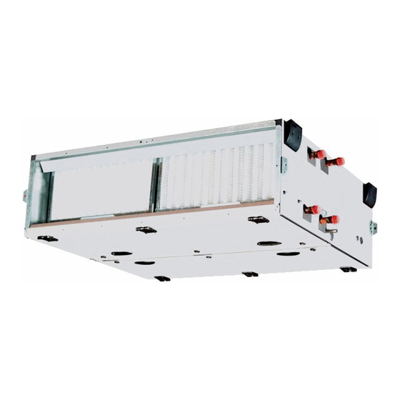
    3 - BESCHREIBUNG DES GERÄTES 3.1 Hersteller-Typenschild Es ist an der Lüftungszentrale befestigt und enthält die Merkmale der Anlage mit Bestellnr. und Kennung. 3.2 Piktogramme Anschlussseite (rechts): 1 – Filtersicherung 2 – Flüssigkeitseintritt 3 – Flüssigkeitsaustritt LUFT 4 – Piktogramm für den Kondensatablauf 5 –...
  • Seite 34: Montage- & Anschlussarbeiten

    4 - MONTAGE- & ANSCHLUSSARBEITEN Die Installation der Geräte hat unter Beachtung der geltenden Gesetze und Vorschriften im Einsatzland zu erfolgen. 4.1 Wahl des AufstellungsMontageortes Horizontal als Deckengerät Vertikal Horizontal auf dem Boden Je nach bestelltem Gerätetyp ist eine Installation an der Decke, auf dem Boden oder vertikal möglich. Damit sich die Türen öffnen lassen, muss ein Mindestabstand eingehalten werden (540 mm, 595 mm, 735 mm, je nach Konfiguration).
  • Seite 35 Befestigung an der Halterung: Länge Modul Kunststoffabdeckung Schwingungsdämpfer Verbindungslasche Schraube H6 ∅ 8 x 80 Verbindung zwischen Gehäusen (für mehrteilige Klimazentralen): - Kleben Sie die PVC-Dichtung 25 x 5 an der Anschlussseite des Zusatzgehäuses auf. - Die Gewindestangen durch die Verbindungslaschen schieben - Das Zusatzgehäuse mit den mitgelieferten Muttern an das Hauptgehäuse schrauben (die Gehäuse müssen ganz genau zueinander ausgerichtet sein, damit die Verbindung dicht ist) Verbindungslasche...
  • Seite 36: Luftkanalanschluss

    4.3 Luftkanalanschluss Keiner der Anschlüsse darf eine mechanische Beanspruchung auf das Gerät ausüben. Auf Ansaug- und Ausblasseite flexible Manschetten verwenden Ansaug- oder Ausblasseite: Baugröße ∅ 4,2 1310 1254 212.3 1880 1824 230.5 C x D Mischluftkasten: 2 Kanäle 3 Kanäle ∅...
  • Seite 37: Stellmotoren

    Schematische Darstellung des Siphons: Bei einem Unterdruck von H im Bereich des Kälteregisters muss die Höhe des Siphons 2H betragen. Auffangwanne unter Unterdruck Bac de récupération en dépression H mmWS Hmm CE Leichtes Gefälle 5/1000 Légère pente 5/1000 Zum Abfluss Vers égout 4.5 Stellmotoren Schließmoment der Türen:...
  • Seite 38 Werkseinstellung Einstellung 1: Einstellung 2: Einstellung 3: Beschreibung Drehzahl über Drehzahl über Drehzahl über Potentiometer Kontakt Bedientasten Parameter Ebene 1 Minimale Drehzahl (Hz) Maximale Drehzahl (Hz) Motor 0,55 kW: 97 , Motor 1,1 kW: 60 , Motor 1,4 kW: 65 Anlauframpe (s / 100 Hz) Auslauframpe (s / 100 Hz) Konfiguration des Drehzahlreglers...
  • Seite 39: Ventilator Mit Ec-Motor

    Werkseinstellung Einstellung 1: Einstellung 2: Einstellung 3: Beschreibung Drehzahl über Drehzahl über Drehzahl über Potentiometer Kontakt Bedientasten Parameter Ebene 3 Letzte Absicherung Absicherung vor der von Pr 55 Absicherung vor der von Pr 56 Absicherung vor der von Pr 57 Bestätigung Leiterlogik SPS ...
  • Seite 40 Leistung (kW) Anzahl Stufen Leistung (kW) Anzahl Stufen Option A Baugröße 025 Baugröße 040 Baugröße 060 Mit Schaltschrank: Zweipunkt oder TRIAC: Schaltschrank nicht lieferbar für die Option A. Optionen Schaltschrank: o Option B: EIN/AUS (2 Stufen) / montiert und verdrahtet o Option C: EIN/AUS (2 Stufen) / Schaltschrank nicht montiert und nicht verdrahtet o Option D: Stufenlose Regelung mit TRIAC (1 Stufe EIN/AUS + 1 stufenlos regelnd) o Option E: Stufenlose Regelung mit TRIAC (1 Stufe EIN/AUS + 1 stufenlos regelnd) / Schaltschrank nicht montiert und nicht...
  • Seite 41: Elektro-Heizregister

    5 - INBETRIEBNAHME Die Inbetriebnahme darf nur von qualifiziertem Personal vorgenommen werden, das über eine Ausbildung im Bereich der Luft- und Klimatechnik verfügt. Bei Betrieb des Gerätes darf keine der Türen geöffnet sein oder werden. Nachdem Strom- und Wasser- und Luftanschlüsse hergestellt wurden, das Gerät in Betrieb nehmen und dabei folgendes kontrollieren: •...
  • Seite 42 Ventilatoren: - Die Versorgungsspannung sowie die Stärke der Sicherungen entsprechend der Stromaufnahme der verschiedenen Elemente prüfen. - Prüfen, ob die Masse angeschlossen ist und das Rad frei dreht. - Den Luftvolumenstrom und den verfügbaren Druck überprüfen Berechnung der Luftmenge: Frei laufendes Rad mit Asynchronmotor Frei laufendes Rad mit EC-Motor √...
  • Seite 43: Wartung / Wartungsintervalle

    6 - WARTUNG / WARTUNGSINTERVALLE Die Stromversorgung der Lüftungszentrale vor allen Arbeiten trennen! Die Wartung darf nur von qualifiziertem Personal durchgeführt werden. Die Maschine über die MMS abschalten und anschließend die Stromversorgung unterbrechen (dabei die Nachlüftungszeit beachten). Da die Scharniere aushängbar sind, können die Türen komplett entfernt werden, um leichter Zugang zu den verschiedenen Komponenten zu bekommen.
  • Seite 44 Manufactured France. Order No.: X0028, 03.2015 . Supersedes order No.: New. Manufacturer reserves the right to change any product specifications without notice. Printed in the European Union.

Inhaltsverzeichnis