Herunterladen Inhalt Inhalt Diese Seite drucken
Danfoss Link HC Installationsanleitung
Vorschau ausblenden Andere Handbücher für Link HC:
Inhaltsverzeichnis

Werbung

Verfügbare Sprachen
  • DE

Verfügbare Sprachen

  • DEUTSCH, seite 13
MAKING MODERN LIVING POSSIBLE
Danfoss Link™ HC Hydronic Controller
Installation Guide
Danfoss Heating Solutions

Werbung

Inhaltsverzeichnis
loading

Inhaltszusammenfassung für Danfoss Link HC

  • Seite 1 MAKING MODERN LIVING POSSIBLE Danfoss Link™ HC Hydronic Controller Installation Guide Danfoss Heating Solutions...
  • Seite 2 Installation Guide Danfoss Link™ HC Installation Guide Installationsanleitung Guide d’installation Installationsmanual Asennusohje Installatiehandleiding Instrukcja instalacji Instalační příručka VIFZL15X © Danfoss 08/2010...
  • Seite 3: Inhaltsverzeichnis

    1: Adding Danfoss Link™ HC to the system . . . . . . . . . . . . . . . . .
  • Seite 4: Introduction

    Danfoss Link™ HC Introduction Danfoss Link™ is a wireless control system for a variety of heating systems . The Danfoss Link™ HC (Hydronic Controller) is a part of this system allowing wireless control of manifolds for water based floor heating/cooling . Output LEDs...
  • Seite 5: Connections

    Installation Guide Danfoss Link™ HC Connections Make sure that all connections to the Danfoss Link™ HC are completed, before connecting to a 230 V power supply . 1: Connecting actuators (24 V) If NC (normally closed) actuators are installed for ON/OFF regulation, no further actuator output con- figuration is needed .
  • Seite 6: 4: Connections For Heating & Cooling

    The external antenna is installed as diverter when there is no transmission possible through a large building, heavy construction or metal barrier, e .g . if the Danfoss Link™ HC is located in a metal cabinet/ 1 . Remove the plastic cover from the antenna con- 2 .
  • Seite 7: Configuration

    Danfoss Link™ HC Configuration 1: Adding Danfoss Link™ HC to the system Adding Danfoss Link™ HC to a system is made from the Danfoss Link™ CC Central Controller . For further information, see the Danfoss Link™ CC instruction manual: Configuration 7: Adding service devices.
  • Seite 8: 2A: Configure Outputs

    3 . Choose your settings and press “OK/Return” . 3: Add an output to a room Configuration Danfoss Link™ HC to a system is made from the Danfoss Link™ CC Central Controller . For further information, see the Danfoss Link™ CC instruction manual: Configuration 7: Adding service devices.
  • Seite 9: 4: Configure A Room

    Installation Guide Danfoss Link™ HC Configuration 4 . If more devices are installed, 5 . Select output . Only available 6 . Select heating emitter and press select a device . outputs are selectable . “Actuator Settings” . 7 . Select actuator type and press “OK/Return”...
  • Seite 10: 5: Remove An Output

    Installation Guide Danfoss Link™ HC Configuration 5: Remove an output 1 . Select “Rooms and Devices” . 2 . Select “Manage Devices” . 3 . Select an existing room . 4 . Select “Room devices” . 5 . Select “Remove a device” .
  • Seite 11: 6: Factory Reset

    Danfoss Link™ HC Configuration 6: Factory reset • Disconnect the power supply for Danfoss Link™ HC . • Wait for green LED to turn off . • Press and hold the Install / Link Test . • While holding the Install / Link Test, reconnect the power supply .
  • Seite 12: Trouble Shooting

    Installation Guide Danfoss Link™ HC Trouble shooting Degraded mode The actuator will be activated with a 25% duty cycle, if the signal from the room thermostat is lost . Flashing output / Output or actuator is short-circuited or the actuator is disconnected .
  • Seite 13 Installationsanleitung Danfoss Link™ HC Inhaltsverzeichnis Einführung . . . . . . . . . . . . . . . . . . . . . . . . . . . . . . . . . . . . . . . . . . . . . . . . . . . . . . . . . . . . . . . . . . . . . . . 15 Anbringung 1: Anbringung an Wand .
  • Seite 14: Einführung

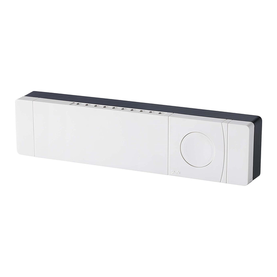
    Installationsanleitung Danfoss Link™ HC Einführung Danfoss Link™ ist ein funkbasiertes Regelungssystem für verschiedene Heizungssysteme . Der Danfoss Link™ Regler HC (Hydronic Controller) ist Teil dieses Systems . Er erlaubt Funksteuerung von Verteilern für wasserbasierte Fußbodenheizung/-kühlung . Ausgangs-LEDs Kesselrelais Pumpenrelais Ausgangsanschlüsse Verbindungsprüfung...
  • Seite 15: Anschlüsse

    Installationsanleitung Danfoss Link™ HC Anschlüsse Vor Anschluss einer 230-V-Stromversorgung sicherstellen, dass alle Anschlüsse zum Danfoss Link™ HC hergestellt sind . 1: Anschluss von Stellantrieben (24 V) Wenn stromlos geschlossene Stellantriebe (NC) zur EIN/AUS-Regelung installiert sind, muss kein weite- rer Stellantriebausgang konfiguriert werden .
  • Seite 16: 4: Anschlüsse Für Heizung Und Kühlung

    7: Externe Antenne Die externe Antenne wird verwendet, wenn eine Funkübertragung durch große Gebäude, dicke Wände mit Armierungen oder Metallsperren NICHT möglich ist, z . B . wenn sich der Danfoss Link™ HC in einem Verteilerschrank aus Metall befindet .
  • Seite 17: Konfiguration

    Danfoss Link™ HC Konfiguration 1: Danfoss Link™ HC zum System hinzufügen Das Hinzufügen des Danfoss Link™ HC in einem System erfolgt über den Zentralregler Danfoss Link™ CC . Weitere Informationen finden Sie im Produkthandbuch des Danfoss Link™ CC: Konfiguration 7: Hinzufügen von Wartungsgeräten 1 .
  • Seite 18: 2A: Ausgänge Konfigurieren

    „OK/Return“ drücken . 3: Ausgang zu einem Raum hinzufügen Die Konfiguration des Danfoss Link™ HC für ein System erfolgt über den Zentralregler Danfoss Link™ CC . Weitere Informationen finden Sie im Produkthandbuch des Danfoss Link™ CC: Konfiguration 7: Hinzufügen von Wartungsgeräten 1 .
  • Seite 19: 4: Raum Konfigurieren

    Installationsanleitung Danfoss Link™ HC Konfiguration 4 . Wenn weitere Geräte installiert 5 . Einen Ausgang auswählen . Nur 6 . Heizungssender auswählen sind, ein Gerät auswählen . verfügbare Ausgänge sind aus- und „Einstellungen Aktuator“ wählbar . drücken . 7 . Einen Stellantriebtyp auswählen und „OK/Return“...
  • Seite 20: 5: Ausgang Entfernen

    Installationsanleitung Danfoss Link™ HC Konfiguration 5: Ausgang entfernen 1 . „Räume u . Geräte“ auswählen . 2 . „Geräte verwalten“ auswählen . 3 . Einen vorhandenen Raum aus- wählen . 4 . „Raumgeräte“ auswählen . 5 . „Gerät entfernen“ auswählen .
  • Seite 21: 6: Rücksetzen Auf Werkseinstellungen

    Danfoss Link™ HC Konfiguration 6: Rücksetzen auf Werkseinstellungen • Die Stromversorgung für den Danfoss Link™ HC trennen . • Warten, bis die grüne LED erlischt . • Die Taste für Verbindungsprüfung drücken und gedrückt halten . • Die Taste für Verbindungsprüfung weiter halten und gleichzeitig die Stromversorgung wieder anschließen .
  • Seite 22: Fehlersuche Und -Behebung

    Installationsanleitung Danfoss Link™ HC Fehlersuche und -behebung Reduzierter Der Stellantrieb wird bei einem Arbeitszyklus von 25 % aktiviert, wenn das Betrieb Signal vom Raumthermostat nicht mehr vorhanden ist . Blinkender Kurzschluss von Ausgang oder Stellantrieb oder Stellantrieb getrennt . Ausgang/...
  • Seite 23 Guide d’installation Danfoss Link™ HC Sommaire Introduction . . . . . . . . . . . . . . . . . . . . . . . . . . . . . . . . . . . . . . . . . . . . . . . . . . . . . . . . . . . . . . . . . . . . . . . . . . 25 Montage 1 : Montage mural .
  • Seite 24: Introduction

    Danfoss Link™ HC Introduction Le Danfoss Link™ est un système de régulation sans fil prévu pour un éventail de systèmes de chauf- fage . Au sein de ce système, le Danfoss Link™ HC (régulateur de système hydronique) assure la régulation sans fil des collecteurs des systèmes de chauffage et de refroidissement par le sol à...
  • Seite 25: Raccordements

    Guide d’installation Danfoss Link™ HC Raccordements Assurez-vous que tous les raccordements au Danfoss Link™ HC sont effectués avant de le connecter à une tension d’alimentation de 230 V . 1 : Raccordement des actionneurs (24 V) Si des actionneurs normalement fermés (NF) sont installés pour la régulation ON/OFF, il n’est pas nécessaire de configurer d’autres sorties d’actionneurs .
  • Seite 26: Raccordement Pour Le Chauffage Et Le Refroidissement

    (à travers un grand bâtiment, une construction lourde ou une barrière métallique par exemple si le Danfoss Link™ HC est placé dans une armoire ou un boîtier en métal) . 1 . Retirez le couvercle en plastique du raccord de 2 .
  • Seite 27: Configuration

    1 : Ajout de Danfoss Link™ HC dans le système L’ajout du Danfoss Link™ HC dans un système se fait à partir du régulateur central Danfoss Link™ CC . Pour de plus amples informations, voir le mode d’emploi du Danfoss Link™ CC : Configuration 7 : Ajout d’appareils de service.
  • Seite 28: 2A : Configuration Des Sorties

    3 : Ajout d’une sortie dans une pièce La configuration du Danfoss Link™ HC dans un système se fait à partir du régulateur central Danfoss Link™ CC . Pour de plus amples informations, voir le mode d’emploi du Danfoss Link™ CC: Configura- tion 7 : Ajout d’appareils de service.
  • Seite 29: Configuration D'une Pièce

    Guide d’installation Danfoss Link™ HC Configuration 4 . Si d’autres unités locales sont 5 . Sélectionnez la sortie . Seules 6 . Sélectionnez une source émet- installées, choisissez-en une . les sorties disponibles sont sé- trice de chaleur et appuyez sur lectionnables .
  • Seite 30: Suppression D'une Sortie

    Guide d’installation Danfoss Link™ HC Configuration 5 : Suppression d’une sortie 1 . Sélectionnez Pièces et unités 2 . Sélectionnez Gérer les unités 3 . Sélectionnez une pièce exis- locales . locales . tante . 4 . Sélectionnez Unités locales de 5 .
  • Seite 31: Réinitialisation Aux Réglages D'usine

    Danfoss Link™ HC Configuration 6 : Réinitialisation aux réglages d’usine • Déconnectez la tension d’alimentation du Danfoss Link™ HC • Attendez que la LED verte s’éteigne . • Appuyez sur le bouton Test d’installation/liaison et maintenez-le enfoncé . • Tout en maintenant ce bouton enfoncé, reconnectez la tension d’alimentation .
  • Seite 32: Dépannage

    Guide d’installation Danfoss Link™ HC Dépannage Mode dégradé Si le signal du thermostat d’ambiance est perdu, l’actionneur est activé avec un cycle de service de 25 % . Clignotement Une sortie ou un actionneur est court-circuité ou un actionneur est décon- des LED d’alarme...
  • Seite 33 1: Tilmelding af Danfoss Link™ HC til systemet . . . . . . . . . . . . . . . .
  • Seite 34: Introduktion

    Installationsvejledning Danfoss Link™ HC Introduktion Danfoss Link™ er et trådløst styresystem til flere forskellige varmesystemer . Danfoss Link™ HC (Hydronic Controller) er en del af dette system, som muliggør trådløs styring af fordelere til vandbaseret gulvvarme/-køling . Udgangslysdioder Install/Link Test Kedelrelæ...
  • Seite 35: Tilslutninger

    Installationsvejledning Danfoss Link™ HC Tilslutninger Sørg for, at alle tilslutninger til Danfoss Link™ HC er udført, før systemet sluttes til en strømforsyning på 230 V . 1: Tilslutning af aktuatorer (24 V) Hvis NC aktuatorer (normal lukket) installeres for ON/OFF regulering, er yderligere konfigurering af aktuator udgangene ikke nødvendig .
  • Seite 36: 4: Tilslutninger For Opvarmning Og Køling

    7: Ekstern antenne Den eksterne antenne installeres, hvor sendesignalet forhindres af en kraftig konstruktions- eller metal- barriere, f .eks hvis Danfoss Link™ HC er placeret i et metalskab . 1 . Fjern plastikdækslet fra antennetilslutningen . 2 . Tilslut den eksterne antenne, og anbring den på den anden side af transmissionsbarrieren .
  • Seite 37: Konfiguration

    Danfoss Link™ HC Konfiguration 1: Tilføjelse af Danfoss Link™ HC til systemet Tilføjelse af Danfoss Link™ HC til et system foretages via Danfoss Link™ CC Central Controller . Du kan få flere oplysninger i instruktionsmanualen til Danfoss Link™ CC: Konfiguration 7: Tilføjelse af serviceenheder.
  • Seite 38: 2A: Konfigurer Udgange

    . på “OK/Tilbage” . 3: Føj en udgang til et rum Konfiguration af Danfoss Link™ HC til et system foretages via Danfoss Link™ CC Central Controller . Du kan få flere oplysninger i instruktionsmanualen til Danfoss Link™ CC: Konfiguration 7: Tilføjelse af serviceenheder.
  • Seite 39: 4: Konfigurer Et Rum

    Installationsvejledning Danfoss Link™ HC Konfiguration 4 . Hvis der er installeret flere enhe- 5 . Vælg udgang . Kun tilgængelige 6 . Vælg varmeafgiver, og tryk på der, skal du vælge en enhed . udgange kan vælges . “Aktuator opsætning” .
  • Seite 40: 5: Fjern En Udgang

    Installationsvejledning Danfoss Link™ HC Konfiguration 5: Fjern en udgang 1 . Vælg “Rum og enheder” . 2 . Vælg “Håndter enheder” . 3 . Vælg et eksisterende rum . 4 . Vælg “Rummets enheder” . 5 . Vælg “Fjern en enhed” .
  • Seite 41: 6: Fabriksnulstillingt

    Danfoss Link™ HC Konfiguration 6: Fabriksnulstilling - reset • Afbryd strømforsyningen til Danfoss Link™ HC . • Vent, til den grønne lysdiode slukker . • Tryk på Install/Link Test, og hold den inde . • Tilslut strømforsyningen igen, mens Install/Link Test holdes inde .
  • Seite 42: Fejlfinding

    Installationsvejledning Danfoss Link™ HC Fejlfinding Frostsikret Hvis rumtermostatsignalet afbrydes, aktiveres aktuatoren med 1/4 af aktuel tilstand cyklustid (åben i 1/4 af tiden - lukket i 3/4 af tiden) . Blinkende Udgangen eller aktuatoren er kortsluttet, eller aktuatoren er afbrudt .
  • Seite 43 1 . Danfoss Link™ HC:n lisääminen järjestelmään . . . . . . . . . . . . . . . . .
  • Seite 44: Johdanto

    Asennusohje Danfoss Link™ HC Johdanto Danfoss Link™ on eri lämmitysjärjestelmien langaton hallintajärjestelmä . Danfoss Link™ HC (vesikierron hallintalaite) on järjestelmän osa, joka mahdollistaa vesipohjaisen lattialämmityksen/-jäähdytyksen jakotukkien langattoman hallinnan . Lähdön LEDit Lähdön kytkennät Kattilan rele Pumpun rele Asennus/yhteyden testaus Ulkoinen Tulot: Etu- antenni Ei käytössä kannen...
  • Seite 45: Toimilaitteiden Kytkeminen

    Asennusohje Danfoss Link™ HC Kytkennät Varmista, että kaikki kytkennät Danfoss Link™ HC:hen ovat paikoillaan ennen kuin kytket laitteen 230 V -virtalähteeseen . 1. Toimilaitteiden kytkeminen (24 V) Jos virransäätelyyn asennetaan NC-toimilaitteita (NC = normaalisti suljettu), ei tarvita muuta toimilait- teen lähdön konfigurointia .
  • Seite 46: Lämmitys-/Jäähdytyskytkennät

    50 Hz 7. Ulkoinen antenni Ulkoinen antenni asennetaan kääntölevyksi silloin, kun lähetys ei ole mahdollista suuren rakennuksen, raskaan rakennelman tai metalliesteen vuoksi, esimerkiksi jos Danfoss Link™ HC sijaitsee metallisessa kaapissa/laatikossa . 1 . Irrota muovinen kansi antennin kytkennästä . 2 . Kytke ulkoinen antenni ja aseta se lähetysesteen toiselle puolelle .
  • Seite 47: Danfoss Link™ Hc:n Lisääminen Järjestelmään

    Danfoss Link™ HC Konfigurointi 1. Danfoss Link™ HC:n lisääminen järjestelmään Danfoss Link™ HC lisätään järjestelmään Danfoss Link™ CC -keskusyksiköstä . Lisätietoja saat Danfoss Link™ CC -käyttöohjeesta, Konfigurointi 7: Palvelulaitteiden lisääminen. 1 . Valitse “Huoneet ja laitteet” . 2 . Valitse “Lisää huoltolaite” .
  • Seite 48: 2A. Lähtöjen Konfigurointi

    3 . Valitse haluamasi asetukset ja paina “OK/Palaa” . 3. Lähdön lisääminen huoneeseen Danfoss Link™ HC:n konfigurointi järjestelmään tapahtuu Danfoss Link™ CC -keskusyksiköstä . Lisätietoja saat Danfoss Link™ CC -käyttöohjeesta, Konfigurointi 7: Palvelulaitteiden lisääminen. 1 . Valitse “Huoneen laitteet” . 2 . Valitse “Lisää laite” .
  • Seite 49: Huoneen Konfigurointi

    Asennusohje Danfoss Link™ HC Konfigurointi 4 . Valitse laite, jos laitteita asenne- 5 . Valitse lähtö . Vain vapaat lähdöt 6 . Valitse säätely ja sitten “Toimi- taan useampia . ovat valittavissa . laitteen asetukset” . 7 . Valitse toimilaitteen tyyppi ja paina “OK/Palaa”...
  • Seite 50: Lähdön Irrottaminen

    Asennusohje Danfoss Link™ HC Konfigurointi 5. Lähdön irrottaminen 1 . Valitse “Huoneet ja laitteet” . 2 . Valitse “Hallitse laitteita” . 3 . Valitse jokin nykyinen huone . 4 . Valitse “Huoneen laitteet” . 5 . Valitse “Poista laite” .
  • Seite 51: Tehdasasetusten Palauttaminen

    Danfoss Link™ HC Konfigurointi 6: Tehdasasetusten palauttaminen • Kytke Danfoss Link™ HC:n jännite pois päältä . • Odota, kunnes vihreä valo sammuu . • Paina ja pidä pohjassa Asennus-/yhteyden testaus -painiketta . • Kun Asennus-/yhteyden testaus -painike on painettuna, kytke tehonsyöttö takaisin .
  • Seite 52: Vianmääritys

    Asennusohje Danfoss Link™ HC Vianmääritys Matalatehoisempi Toimilaite aktivoituu toimimaan 25 %:n teholla, jos huonetermostaatin käyttötila signaali kadotetaan . Vilkkuvat lähdöt / Lähtö tai toimilaite on mennyt oikosulkuun tai toimilaite on kytketty irti . hälytyksen merkkivalot Tekniset tiedot -taulukko Lähetystaajuus 862,42 Mhz Kantama tavallisissa rakennuksissa enintään 30 metriä...
  • Seite 53 1: Danfoss Link™ HC aan het systeem toevoegen . . . . . . . . . . . . . . . . .
  • Seite 54: Inleiding

    Danfoss Link™ HC Inleiding Danfoss Link™ is een draadloos regelsysteem voor diverse verwarmingssystemen . De Danfoss Link™ HC (Hydronic Controller – Individuele Regelaar) maakt deel uit van dit nieuwe systeem dat een draadloze regeling van verdelers voor watergebaseerde vloerverwarming/-koeling mogelijk maakt .
  • Seite 55: 1: Actuatoren Aansluiten

    Installatiehandleiding Danfoss Link™ HC Aansluitingen Verzeker u ervan dat alle aansluitingen naar de Danfoss Link™ HC zijn gemaakt voordat u de eenheid aansluit op een 230 V-voedingsbron . 1: Actuatoren aansluiten (24 V) Als voor de AAN/UIT-regeling NC-actuatoren (normaal gesloten) worden geïnstalleerd, is geen verdere configuratie van de actuatoruitgangen nodig .
  • Seite 56: 4: Aansluitingen Voor Verwarming/Koeling

    De externe antenne wordt geïnstalleerd als doorzendantenne wanneer er geen transmissie mogelijk is door een groot gebouw, zware constructies of metalen barrières, bijv . als de Danfoss Link™ HC in een metalen kast is geplaatst . 1 . Verwijder het kunststof afdekplaatje van de 2 .
  • Seite 57: 1: Danfoss Link™ Hc Aan Het Systeem Toevoegen

    Configuratie 1: Danfoss Link™ HC aan het systeem toevoegen Het toevoegen van de Danfoss Link™ HC aan een systeem gebeurt via de Danfoss Link™ CC Centrale Regelaar . Raadpleeg Configuratie 7: Serviceapparaten toevoegen in de Danfoss Link™ CC instructiehand- leiding voor meer informatie .
  • Seite 58: 2A: Uitgangen Configureren

    “OK/Terug” . 3: Een uitgang aan een kamer toevoegen Het configureren van de Danfoss Link™ HC voor een systeem gebeurt via de Danfoss Link™ CC Cen- trale Regelaar . Raadpleeg Configuratie 7: Serviceapparaten toevoegen in de Danfoss Link™ CC instruc- tiehandleiding voor meer informatie .
  • Seite 59: 4: Een Kamer Configureren

    Installatiehandleiding Danfoss Link™ HC Configuratie 4 . Selecteer een apparaat wanneer 5 . Selecteer een uitgang . Alleen 6 . Selecteer de warmteafgever en er meerdere apparaten zijn ge- de beschikbare uitgangen zijn druk op “Actuatorinstellingen” . installeerd . te selecteren .
  • Seite 60: 5: Een Uitgang Verwijderen

    Installatiehandleiding Danfoss Link™ HC Configuratie 5: Een uitgang verwijderen 1 . Selecteer “Kamers en appara- 2 . Selecteer “Apparaatbeheer” . 3 . Kies een bestaande kamer . ten” . 4 . Selecteer “Kamerapparaten” . 5 . Selecteer “Apparaat wissen” .
  • Seite 61: 6: Fabrieksinstellingen Herstellen

    Danfoss Link™ HC Configuratie 6: Fabrieksinstellingen herstellen • Koppel de Danfoss Link™ HC los van de voedingsbron . • Wacht tot de groene led uit is . • Druk op knop Installatie/Verbindingstest en houd deze ingedrukt . • Sluit de eenheid opnieuw aan op de voedingsbron terwijl u de knop Installatie/Verbindingstest ingedrukt houdt .
  • Seite 62: Problemen Verhelpen

    Installatiehandleiding Danfoss Link™ HC Problemen verhelpen Gereduceerde De actuator zal worden geactiveerd met een werkcyclus van 25% wanneer modus het signaal vanaf de kamerthermostaat uitvalt . Knipperende De uitgang of de actuator is kortgesloten of de actuator is losgekoppeld .
  • Seite 63 Instrukcja instalacji Danfoss Link™ HC Spis treści Wstęp . . . . . . . . . . . . . . . . . . . . . . . . . . . . . . . . . . . . . . . . . . . . . . . . . . . . . . . . . . . . . . . . . . . . . . . . . . . . . . . . . . . 65 Montaż...
  • Seite 64: Wstęp

    Instrukcja instalacji Danfoss Link™ HC Wstęp Danfoss Link™ to bezprzewodowy system sterowania do różnorodnych układów grzewczych . Sterownik Danfoss Link™ HC (sterownik hydroniczny) stanowi część niniejszej instalacji i umożliwia bezprzewodowe sterowanie rozdzielaczami wodnego systemu ogrzewania/chłodzenia podłogowego . Diody wyjścia Test instalacji/ Przekaźnik Przekaźnik...
  • Seite 65: Instrukcja Instalacji

    3: Podłączanie funkcji zdalnej Funkcja zdalna zapewnia ustawienie temperatury pomieszczenia na poziomie 15°C dla wszystkich ter- mostatów pomieszczeń, lecz ustawienie to można zmienić za pomocą sterownika Danfoss Link™ CC . 1 . Podłączyć wyłącznik zewnętrzny do zacisków 2 . Zamocować przewód .
  • Seite 66: 4: Podłączanie Chłodzenia I Ogrzewania

    Antena zewnętrzna jest instalowana jako rezystor bocznikujący w miejscach uniemożliwia- jących nadawanie sygnałów z powodu określonej wielkości lub konstrukcji budynku lub zamontowania bariery metalowej, np . w przypadku, gdy sterownik Danfoss Link™ HC znajduje się w szafce metalowej . 1 . Zdjąć plastikową osłonę ze złącza anteny .
  • Seite 67: 1: Dodawanie Danfoss Link™ Hc Do Systemu

    1: Dodawanie Danfoss Link™ HC do systemu Sterownik Danfoss Link™ HC dodaje się do systemu z poziomu sterownika centralnego Danfoss Link™ CC . Więcej informacji na ten temat znajduje się w instrukcji obsługi Danfoss Link™ CC: Konfiguracja 7: Dodawanie urządzeń serwisowych .
  • Seite 68: 2B: Konfiguracja Wejść

    3: Dodawanie wyjścia do pomieszczenia Konfigurację sterownika Danfoss Link™ HC w systemie wykonuje się z poziomu sterownika centralne- go Danfoss Link™ CC . Więcej informacji na ten temat znajduje się w instrukcji obsługi Danfoss Link™ CC: Konfiguracja 7: Dodawanie urządzeń serwisowych .
  • Seite 69: 4: Konfiguracja Pomieszczenia

    Instrukcja instalacji Danfoss Link™ HC Konfiguracja 4 . Jeżeli zainstalowano więcej 5 . Wybrać wyjście . Można wybrać 6 . Wybrać źródło ciepła i nacisnąć urządzeń, należy wybrać to wyłącznie dostępne wyjścia . “Ustawienia siłownika” . pożądane . 7 . Wybrać typ urządzenia urucha- miającego, a następnie nacisnąć...
  • Seite 70: 5: Usuwanie Wyjścia

    Instrukcja instalacji Danfoss Link™ HC Konfiguracja 5: Usuwanie wyjścia 1 . Wybrać “Pomieszczenia i urzą- 2 . Wybrać “Zarządzaj urządze- 3 . Wybrać istniejące pomiesz- dzenia” . niami” . czenie . 4 . Wybrać “Urządzenia w pomiesz- 5 . Wybrać “Usuń urządzenie” .
  • Seite 71: 6: Przywracanie Ustawień Fabrycznych

    Danfoss Link™ HC Konfiguracja 6: Przywracanie ustawień fabrycznych • Odłączyć źródło zasilania od sterownika Danfoss Link™ HC . • Odczekać, aż zgaśnie zielona dioda . • Nacisnąć i przytrzymać “Test instalacji/połączenia” . • Przytrzymując “Test instalacji/połączenia”, ponownie podłączyć źródło zasilania .
  • Seite 72: Rozwiązywanie Problemów

    Instrukcja instalacji Danfoss Link™ HC Rozwiązywanie problemów Tryb ograniczony Urządzenie uruchamiające zostanie aktywowane z obciążeniem równym 25% pełnego obciążenia, jeżeli nastąpi utrata sygnału z termostatu w którymś z pomieszczeń . Migające dioda / -y Zwarcie na wyjściu lub w urządzeniu uruchamiającym; urządzenie urucha- wyjścia / alarmu...
  • Seite 73 1: Přidání regulátoru Danfoss Link™ HC do systému . . . . . . . . . . . . . . . .
  • Seite 74: Úvod

    Vytápění/Chlazení (externí vypínač) Montáž Regulátor Danfoss Link™ HC musí být vždy namontován v horizontální vzpřímené poloze . 1: Montáž na stěnu 1 . Sundejte přední a boční kryty a proveďte montáž pomocí vrutů a hmoždinek . 2: Montáž na DIN lištu 1 .
  • Seite 75: 1: Připojení Aktuátorů

    Instalační příručka Danfoss Link™ HC Připojení Před připojením 230V zdroje zkontrolujte, zda jsou k regulátoru Danfoss Link™ HC připojeny všechny kabely . 1: Připojení aktuátorů (24 V) Pokud jsou pro regulaci vypínání instalovány aktuátory NC (rozpínací), není potřeba provádět žádnou další...
  • Seite 76: 4: Připojení Pro Vytápění A Chlazení

    7: Externí anténa Externí anténa se instaluje jako usměrňovač, pokud není možné zajistit přenos ve velké budově nebo kvůli robustní konstrukci či kovové překážce, např . když je regulátor Danfoss Link™ HC umístěn v kovo- vé skříni . 1 . Sundejte z přípojky antény plastový kryt .
  • Seite 77: 1: Přidání Regulátoru Danfoss Link™ Hc Do Systému

    Danfoss Link™ HC Konfigurace 1: Přidání regulátoru Danfoss Link™ HC do systému Regulátor Danfoss Link™ HC se připojuje k systému pomocí centrálního ovladače Danfoss Link™ CC . Další informace naleznete v návodu k použití ovladače Danfoss Link™ CC: Konfigurace 7: Přidávání po- mocných zařízení.
  • Seite 78: 2A: Konfigurace Výstupů

    3: Přidání výstupu do místnosti Konfigurace regulátoru Danfoss Link™ HC v systému se provádí pomocí centrálního ovladače Danfoss Link™ CC . Další informace naleznete v návodu k použití ovladače Danfoss Link™ CC: Konfigurace 7: Při- dávání pomocných zařízení. 1 . Vyberte položku Zařízení míst- 2 .
  • Seite 79: 4: Konfigurace Místnosti

    Instalační příručka Danfoss Link™ HC Konfigurace 4 . Pokud je nainstalováno více za- 5 . Vyberte výstup . Vybrat lze pou- 6 . Vyberte vyzařovač tepla a řízení, vyberte zařízení . ze dostupné výstupy . stiskněte tlačítko Nastavení aktuátoru .
  • Seite 80: 5: Odebrání Výstupu

    Instalační příručka Danfoss Link™ HC Konfigurace 5: Odebrání výstupu 1 . Vyberte položku Místnosti a 2 . Vyberte položku Správa 3 . Vyberte stávající místnost . zařízení . zařízení . 4 . Vyberte položku Zařízení 5 . Vyberte položku Odebrat 6 .
  • Seite 81: 6: Obnovení Továrních Nastavení

    Danfoss Link™ HC Konfigurace 6: Obnovení továrních nastavení • Odpojte zdroj napájení regulátoru Danfoss Link™ HC . • Vyčkejte, dokud nezhasne zelená kontrolka . • Stiskněte a podržte tlačítko Instalovat/Test spojení . • Držte tlačítko stisknuté a znovu zapojte zdroj napájení .
  • Seite 82: Řešení Problémů

    Instalační příručka Danfoss Link™ HC Řešení problémů Režim sníženého Pokud dojde ke ztrátě signálu z pokojového termostatu, aktuátor výkonu bude aktivován s 25% pracovním cyklem . Blikající Došlo ke zkratování výstupu nebo aktuátoru nebo k odpojení aktu- kontrolky átoru .
  • Seite 83 Installation Guide Danfoss Link™ HC VIFZL15X © Danfoss 08/2010...
  • Seite 84 Danfoss A/S DK • 7100 Vejle Phone +45 7488 8500 +45 7488 8501 VIFZL15X © Danfoss 08/2010...

Inhaltsverzeichnis