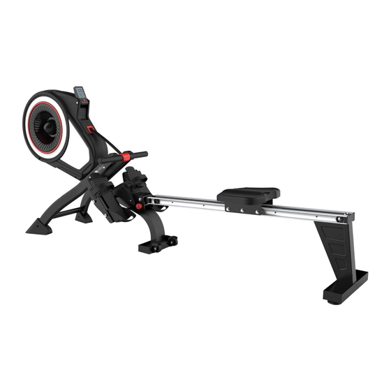
Seite 1
GEBRAUCHSANLEITUNG TURBINEN RUDERMASCHINE USER MANUAL TURBINE ROWER MODE D'EMPLOI RAMEUR TURBINE MANUALE UTENTE REMO DE TURBINA MANUAL DE INSTRUCCIONES VOGATORE A TURBINA SP-MR-010...
Seite 2
Sehr geehrte Kundin, Sehr geehrter Kunde, Wir gratulieren Ihnen zu Ihrem neuen SportPlus Produkt und sind überzeugt, dass Sie mit diesem Produkt zufrieden sein werden. Um eine stets optimale Funktion und Leistungsbereitschaft Ihres Produktes zu gewähr- leisten, beachten Sie Folgendes: Bevor Sie das Produkt das erste Mal benutzen, lesen Sie sich die folgende Bedienungs- anleitung sorgfältig durch! Das Produkt ist mit Sicherheitsvorrichtungen ausgestattet.
Seite 3
Computerfunktionen: Zeit, Geschwindigkeit, Distanz, Gesamt- zähler Ruderschläge, Umdrehungen/Min., ca. Kalorienverbrauch, Pulsanzeige. • Funkempfang: 5 kHz (www.sportplus.de/konformitaetserklaerung) 2. SICHERHEITSHINWEISE VERWENDUNGSZWECK • Das Produkt ist für die Nutzung im häuslichen Bereich konzipiert und nicht für medi- zinische oder gewerbliche Zwecke geeignet. •...
Seite 4
2. SICHERHEITSHINWEISE • Benutzen Sie das Produkt immer auf einem waagerechten, ebenen, rutschfesten und soliden Untergrund. Benutzen Sie es nie in der Nähe von Wasser und halten Sie aus Sicherheitsgründen rund um das Produkt einen ausreichenden Freiraum von mind. 1 Meter ein. •...
Seite 5
2. SICHERHEITSHINWEISE • Entfernen Sie sämtliches Verpackungsmaterial und legen dann die einzelnen Teile auf eine freie Fläche. Dieses verschafft Ihnen einen Überblick und erleichtert das Zu- sammenbauen. Schützen Sie die Aufbaufläche durch eine Unterlage vor Verschmut- zen bzw. Verkratzen. • Überprüfen Sie nun anhand der Teileliste, ob alle Bauteile vorhanden sind.
Seite 6
4. VORBEREITUNG Auf dieser Seite finden Sie alle Teile die in den folgen Schritten montiert werden. 14L/R 11 L/R 8 L/R Bezeichnung Anz. Hauptrahmen Standfuß vorne Mittlerer Standfuß Hinterer Standfuß Sitz Schiene 14 L/R Pedale L/R 11 L/R Ablage für Zugstange (L/R) Fußkappe Schrauben zur Pedal-Befestigung Sicherungsstift...
Seite 7
4. VORBEREITUNG Auf dieser Seite finden Sie alle Kleinteile (Schrauben, Unterlegscheiben, Muttern und Werkzeuge) abgebildet, welche Sie zur Montage des Gerätes benötigen. Alle diese Teile liegen auf einer Blisterkarte eingeschweißt der Kartonverpackung bei. Bezeichnung Abbildung Anz. Innensechskantschraube M8x16mm Innensechskantschraube M8x20mm Gummipuffer Federscheibe Unterlegscheibe...
Seite 8
5. MONTAGEANLEITUNG 1. Schritt Nehmen Sie den mittleren Standfuß (78) mit den integrierten Transportrollen zur Hand und fixieren Sie diesen mit zwei Schrauben (19) und zwei Unterlegscheiben (43) am Hauptrahmen (1).
Seite 9
5. MONTAGEANLEITUNG 1 34 2. Schritt Schieben Sie die Schiene (45) in die U-förmige Aufnahme am Hauptrahmen (1). Befes- tigen Sie die Schiene mit einer Achse (41) und 2 Sätzen Schrauben (34), Federschei- ben (37) und Unterlegscheiben (38). Zum Schluss stecken Sie den Sicherungsstift (35) wieder in das vordere Loch im Hauptrahmen (1).
Seite 10
5. MONTAGEANLEITUNG 3. Schritt Schieben Sie den Sitz (53) auf die Schiene (45). Bringen Sie 2 Gummipuffer (36) an der Schiene (45) an und sichern Sie mit 2 Schrauben (34). Befestigen Sie 2 Fußkappen (55) am hinteren Standfuß (54) bevor Sie den hinteren Standfuß...
Seite 11
5. MONTAGEANLEITUNG Vorsicht Quetschgefahr! Am Gelenk des Produkts wirken große Hebelkräfte. Fassen Sie das Produkt nicht im Bereich des Knickgelenks an. 4. Schritt Drehen Sie den Hauptrahmen und stellen Sie das hintere Stützrohr auf den Boden. Nehmen Sie die vier Blechschrauben (10) aus den Endkappen für das vordere Stabilisa- tor-Rohr (8 L/R) heraus.
Seite 12
5. MONTAGEANLEITUNG Vorsicht Quetschgefahr! Am Gelenk des Produkts wirken große Hebelkräfte. Fassen Sie das Produkt nicht im Bereich des Knickgelenks an. 5. Schritt Drehen Sie den Hauptrahmen und stellen Sie das vordere Stützrohr auf den Boden. Ziehen Sie den Sicherungsstift (35) heraus und klappen Sie den Hauptrahmen auseinan- der.
Seite 13
5. MONTAGEANLEITUNG 6m m 6. Schritt Stecken Sie die zwei Ablagen für die Zugstange (11 L/R) auf die Öffnungen an der Vor- derseite des Hauptrahmens (1). Befestigen Sie dann das linke und rechte Pedal (14 L/R) an die jeweilige Seite des Haupt- rahmens (1) und befestigen Sie diese mit je zwei Innensechskantschrauben (13).
Seite 14
6. VORBEREITEN / ABSTELLEN Computer / Zugstange Der Computer kann (24) auf- oder zugeklappt werden. Die Zugstange (29) kann in die Ablage für die Zugstange (11 L/R) eingehängt werden. Pedale einstellen Stellen Sie die Pedale (14 L/R) auf Ihre Fußgröße ein, indem Sie den Schlaufenumfang anpassen.
Seite 15
6. VORBEREITEN / ABSTELLEN Vorsicht Quetschgefahr! Am Gelenk des Produkts wirken große Hebelkräfte. Fassen Sie das Produkt nicht im Bereich des Knickgelenks an. Zusammenklappen Sie können den Sicherungsstift (35) herausziehen und die Schiene (45) hochklappen, wenn Sie das Gerät nicht benutzen. Sichern Sie das zusammengeklappte Gerät: Stecken Sie den Sicherungsstift wieder in das ursprüngliche Loch.
Seite 16
7. BEDIENUNG DES COMPUTERS Tastenfunktionen: MODE/RESET: • Drücken Sie die Taste MODE/RESET, um zwischen den verschie- denen Funktionen auswählen zu können: Time (Zeit), Count (An- zahl Ruderschläge), Distance (Strecke), Calories (ca. Kalorienver- brauch) und Pulse (Herzfrequenz). Die ausgewählte Funktion blinkt nun.
Seite 17
7. BEDIENUNG DES COMPUTERS Funktionen: SCAN (Scannen): Drücken Sie die Taste MODE/RESET bis SCAN auf der Display- anzeige erscheint. Die Anzeige zeigt für jeweils 5 Sekunden Time (Zeit), Count (An- zahl Ruderschläge), Distance (Strecke), Calories (ca. Kalorienverbrauch) und Pulse (Herzfrequenz) an. TIME (Zeit): Die Zeit zeigt Ihnen Ihre verstrichene Trainingszeit bis zu 99:59 Minuten Count (Anzahl Ruderschläge): Zeigt die Anzahl der Ruderschläge der aktuellen Trainingseinheit an.
Seite 18
8. TRAININGSTIPPS WICHTIGE HINWEISE ZUM TRAINING • Bevor Sie mit dem Training beginnen, konsultieren Sie Ihren Arzt. Fragen Sie ihn, in welchem Umfang ein Training für Sie angemessen ist. Falsches oder übermäßiges Training kann zu Gesundheitsschäden führen. • Vermeiden Sie eine Überbelastung Ihres Körpers. Trainieren Sie nicht, wenn Sie müde oder erschöpft sind.
Seite 19
9. ÜBUNG Position • Setzen Sie sich auf den Sitz und platzieren Sie Ihre Füße vorsichtig in den Pedalen. • Nehmen Sie die Zugstange von der Ablage. • In der Anfangsposition sollten die Arme gestreckt, der Oberkörper leicht nach vorne geneigt und Beine angewinkelt sein.
Seite 20
12. FEHLERSUCHE FEHLER URSACHE WAS TUN? Computer keine Stromversorgung Batterien fehlen – einlegen Keine Anzei- Batterien leer – neue einlegen ge oder keine Batterien falsch eingelegt – richtig einlegen Funktion keine Kabelverbindung Kabelverbindung überprüfen Wenn dies nicht hilft, Service anrufen Mechanik –...
Seite 21
Servicezeit: Montag bis Freitag von 9.00 bis 18.00 Uhr Servicehotline: +49 (0)40 - 780 896 – 35* E-Mail: Service@SportPlus.org URL: http://www.sportplus.de/ *Nationales Festnetz, Gesprächsgebühren sind von Ihrem Telefonanbieter / Ihrem Te- lefonvertrag abhängig. Bitte achten Sie darauf, dass Sie hierzu folgende Informationen zur Hand haben.
Seite 22
14. GEWÄHRLEISTUNGSBESTIMMUNGEN SportPlus versichert, dass das Produkt, auf das sich die Gewährleistung bezieht, aus qualitativ hochwertigen Materialien hergestellt und mit äußerster Sorgfalt überprüft wurde. Voraussetzung für die Gewährleistung ist die Bedienung und der ordentliche Aufbau ge- mäß Bedienungsanleitung. Durch unsachgemäße Nutzung und / oder unsachgemäßen Transport kann die Gewährleistung entfallen.
Seite 25
16. TEILELISTE Beschreibung und Daten Anzahl Hauptrahmen Nylonmutter Laufrolle Innensechskantschraube Quadratische Endkappe Rutschfestes Pad Blechschraube 8 L/R Endkappe für vorderes Stabilisator-Rohr (L/R) Vorderes Stützrohr Blechschraube 11 L/R Ablage für Zugstange (L/R) U-förmige Pedalplatte Innensechskantschraube für Pedal 14 L/R Pedal ( L/R ) Vorderfußstütze Kreuzschlitzschraube Nylonmutter...
Seite 26
Beschreibung und Daten Anzahl Unterlegscheibe Ø8xØ25mm Lagerbuchse 40 L/R Endkappe für Schiene ( L/R ) Achse für Führungsschiene Innensechskantschraube M8x40mm Unterlegscheibe Ø8xØ17mm Vierkantscheibe Schiene 46 L/R Führungsschiene (L/R) Blechschraube Achse für Laufrolle Laufrolle Kreuzschlitzschraube Innensechskantschraube Befestigungsplatte für Sitzschale Sitz Hinteres Stützrohr Fußkappe Fußspange 57 L/R Luftkanal (L/R)
Seite 27
Beschreibung und Daten Anzahl Federkupplung Riemenscheibe Mittleres Stützrohr Gewebeklebeband Lager Kettenabdeckung (L/R) Riemen Blechschraube Pulvermetall Riemenscheibe Achse für Riemenscheibe Luftöffnung...
Seite 28
Dear Customer, Congratulations for choosing a SportPlus product. We have every expectation t at ou satisfied our ne To guarantee optimal function of this product, please adhere to the following instructions: Before using this product for the first time, please read the manual carefull The product has been designed with safet features.
Seite 29
• Displa ing time, speed, distance, total count of strokes, • Computer features: rounds per minute, approx. calorie consumption, and pulse. k z (www.sportplus.de konformitaetserklaerung) • Radio reception: 2. SAFETY INSTRUCTIONS INTENDED PURPOSE • This product is intended for household use and is not suitable for medicinal or commercial purposes.
Seite 30
2. SAFETY INSTRUCTIONS Make sure that no more than one person uses the product at a time. • Alwa s use the product on a horizontal, level, nonslip and solid surface. ever use • the product near water and make sure there is a safet clearance of at least meter on all sides of the product.
Seite 31
2. SAFETY INSTRUCTIONS Remove all packaging materials and place all individual components on a free surface. • This will give ou a good overview and simplif assembl . Shield the assembl surface from filth and scratching b la ing down suitable padding. heck the components against the components list to make sure all are present.
Seite 32
4. PREPARATION This page lists all the components that require assembl in the following steps. 14L/R 11 L/R 8 L/R Description Frame Front foot Center foot Rear stabilizer Seat Rail Footplate Pull bar stacks ( R) Foot cap Screws for footplate installation Safet pin End cap for front stabilizer tube ( R)
Seite 33
4. PREPARATION This page depicts all the small parts (screws, washers, nuts and tools) that ou will require for assembl . All these parts are included in the packaging, shrink wrapped on a blister card. llustration Description exagon socket screw exagon socket screw Rubber pads Spring washer...
Seite 34
5. ASSEMBLY INSTRUCTIONS Step 1 old the center foot ( ) with the built in transport castors and attach it to the frame ( ) using two screws ( ) and two washers (...
Seite 35
5. ASSEMBLY INSTRUCTIONS 1 34 Step 2 Slide the rail ( ) into the U shaped mount on the frame ( ). Secure the rail using one axis ( ) and sets of screws ( ), spring washers ( ) and washers ( ).
Seite 36
5. ASSEMBLY INSTRUCTIONS Step 3 Slide the seat ( ) onto the rail ( ). Attach rubber pads ( ) to the rail ( ) and secure with screws ( Attach foot caps ( ) to the rear stabilizer ( ) before installing the rear stabilizer to the runner.
Seite 37
5. ASSEMBLY INSTRUCTIONS reat leverage is applied to the product s oint. Caution Risk of crushing! Do not touch the product near the articulated oint. Step 4 Turn the frame and place the rear support frame on the floor. Remove the four self tapping screws ( ) from the end caps of the front stabilizer tube R).
Seite 38
5. ASSEMBLY INSTRUCTIONS reat leverage is applied to the product s oint. Caution Risk of crushing! Do not touch the product near the articulated oint. Step 5 Turn the frame and place the front support frame on the floor. Remove the safet pin ( ) and unfold the frame.
Seite 39
5. ASSEMBLY INSTRUCTIONS 6m m Step 6 nstall the two pull bar stacks ( R) on the holes at the front of the frame ( ). Then attach the left and right footplates ( R) to the respective side of the frame ( ) using two hexagon socket screws ( ) each.
Seite 40
PREPARATION / SETTING UP Computer / draw bar The computer ( ) can be folded open or close. The draw bar ( ) can be hooked into the draw bar holder ( Setting the pedals Ad ust the pedals ( R) to our foot size b ad usting the strap circumference.
Seite 41
6. PREPARATION / SETTING UP reat leverage is applied to the product s oint. Caution Risk of crushing! Do not touch the product near the articulated oint. Folding ou ma remove the safet pin ( ) and flip up the rail ( ) when not using the product.
Seite 42
7. USING THE COMPUTER Button functions: Press the MODE/RESET button to switch between different functions: MODE/RESET: • Time, count, distance, calories (approx.), and pulse. The selected function flashes. Press and hold the MODE/RESET button for 2 seconds to reset all •...
Seite 43
7. USING THE COMPUTER Functions: SCAN: Press the MODE/RESET button until S A appears in the displa . The displa will show time, count, distance, (approx.) calories and pulse for seconds each. TIME: The time displa indicates the training time of up to minutes.
Seite 44
8. TIPS FOR Y OUR WORKOUT IMPORTANT NOTES ON TRAINING Please consult our ph sician before beginning training. Ask our ph sician about • the extent of training appropriate for ou. mproper or excessive training ma result in damage to health. Do not overstrain our own bod .
Seite 45
9. EXERCISE Position Sit on the seat and carefull place our feet in the pedals. • Remove the draw bar from the rack. • n the starting position, our arms should be outstretched, our torso bent slightl • forward and our legs bent. Exercise steps Stretch our legs without moving our torso.
Seite 46
12. TROUBLESHOOTING PROBLEM CAUSE WHAT TO DO? Computer o displa or no o power suppl o batteries insert batteries Depleted batteries insert new batteries function Batteries inserted incorrectl insert correctl o cable connection heck cable connection f this does not solve the problem, contact our service center.
Seite 47
Availability : Monday to Friday from 9:00 am to 6:00 pm Service hotline: +44 - 203 318 4415* E-Mail: Service@SportPlus.org URL: http://www.sportplus.de/ ational fixed line network, call charges depend on our phone compan our phone contract.
Seite 48
14. TERMS OF WARRANTY SportPlus guarantees that the product this warrant applies to was manufactured using high qualit materials and has been inspected with the utmost attention. The operation and assembl of the product according to the user manual is a precondition of this warrant .
Seite 51
16. PART LIST Description and information Anzahl Frame lon nut Roller (small) exagon socket screw Square end cap Anti skid pad Self tapping screw End cap for front stabilizer tube ( R) Front support frame Self tapping screw Pull bar stacks ( R) U shaped pedal plate Footplate hexagon socket screw R Footplate ( R)
Seite 52
Description and information Anzahl asher Bearing R Rail end cap ( R) uide rail axis exagon socket screw M x asher Square washer Rail uide rail ( R) Self tapping screw Runner axis Roller (small) Phillips screw exagon socket screw Seat shell mounting plate Seat Rear support frame...
Seite 53
Description and information Anzahl Spring coupling Belt wheel Center support tube Duct tape Bearing hain cover ( Belt Self tapping screw Powder metal Belt wheel Belt wheel axis Air opening...
Seite 54
Chè re cliente, Cher client, Nous vous fé licitons pour l' achat de votre nouveau produit SportPlus et sommes convaincus que vous en serez satisfait. Pour garantir un bon fonctionnement et une performance optimale de votre produit, nous vous prions de respecter ce qui suit : Avant d’...
Seite 55
• Ré ception radio : 5 kHz (www.sportplus.de konformitaetserklaerung) 2. CONSIGNES DE SÉ CURITÉ USAGE PRÉ VU • Le produit est conç u pour une utilisation dans le secteur privé et non pas dans un but m dical ni des fins commerciales.
Seite 56
2. CONSIGNES DE SÉ CURITÉ • Utilisez toujours le produit sur un sol plane, antid é rapant, horizontal et solide. Ne l' utilisez jamais à proximité de l' eau et pour des raisons de sé curité , assurez autour du produit un espace libre suffisant d au moins m tre.
Seite 57
2. CONSIGNES DE SÉ CURITÉ • Veuillez considé rer qu’ il existe toujours un risque de blessure lors de l' utilisation d’ outils et d’ activité s de bricolage. C’ est pourquoi, vous devez agir minutieusement et prudemment lors du montage du produit. •...
Seite 58
4. PRÉ PARATION Sur cette page, vous trouverez toutes les pi è ces qui sont à monter dans les é tapes suivantes. 14L/R 11 L/R 8 L/R N° Dé signation Quant. Cadre principal Pied avant Pied central Pied de support arriè re Siè...
Seite 59
4. PRÉ PARATION Sur cette page, vous trouvez toutes les petites pi è ces illustr é es (vis, rondelles plates, é crous et outils) que vous avez besoin pour l' assemblage de l' appareil. Toutes ces piè ces sont conditionné es sur une carte blister pelliculé e sur l' emballage carton. N°...
Seite 60
5. NOTICE DE MONTAGE 1. é tape Prenez le pied central ( ) avec les roulettes de transport int gr es en main et fixez le avec deux vis (19), deux rondelles plates (43) au cadre principal (1).
Seite 61
5. NOTICE DE MONTAGE 1 34 2. é tape Faites glisser le rail (45) dans le passage en forme de U sur le cadre principal (1). Fixez le rail avec un axe (41) et 2 jeux de vis (34), des rondelles ressorts (37) et des rondelles plates ( ).
Seite 62
5. NOTICE DE MONTAGE 3. é tape Poussez le si è ge (53) sur le rail (45). Placez les 2 tampons en caoutchouc (36) sur le rail (45) et sé curisez-le avec 2 vis (34). Fixez 2 capuchons pour pied (55) sur le pied arri è re (54) avant que vous n ' attachiez le pied arriè...
Seite 63
5. NOTICE DE MONTAGE Attention, risque de pincement ! L' articulation du produit est soumise à des effets importants de levier. Ne touchez pas la zone de l' articulation du produit. 4. é tape Tournez le cadre principal et placez le support tubulaire arriè re au sol. Enlevez les quatre vis en tô...
Seite 64
5. NOTICE DE MONTAGE Attention, risque de pincement ! L' articulation du produit est soumise à des effets importants de levier. Ne touchez pas la zone de l' articulation du produit. 5. é tape Tournez le cadre principal et placez le support tubulaire avant au sol. Tirez sur la goupille de sé...
Seite 65
5. NOTICE DE MONTAGE 6m m 6. é tape Mettez les deux reposoirs pour la barre de traction (11 L/R) sur les ouvertures à l' avant du cadre principal (1). Attachez ensuite la p é dale de gauche et de droite (14 L/R) de chaque c ô t é du cadre principal ( ) et fixez les p dales avec chaque fois deux vis (...
Seite 66
6. PRÉ PARATION / MISE EN PLACE Ordinateur/barre de traction L' ordinateur peut (24) ê tre plié ou dé plié . La barre de traction (29) peut ê tre accroché e dans le reposoir pour la barre de traction (11 L/R). Ré...
Seite 67
6. PRÉ PARATION / MISE EN PLACE Attention, risque de pincement ! L' articulation du produit est soumise à des effets importants de levier. Ne touchez pas la zone de l' articulation du produit. Pliage Vous pouvez enlever la goupille de sé curité (35) et relever le rail (45) si vous n' utilisez pas l' appareil.
Seite 68
7. UTILISATION DE L' ORDINATEUR Fonctions des touches : MODE/RESET : • Appuyez sur la touche MODE/RESET pour pouvoir basculer entre les diffé rentes fonctions : Time (duré e), Count (nombre de coups de rame), Distance (distance), Calories (consommation de calories approximative) et Pulse (fré...
Seite 69
7. UTILISATION DE L' ORDINATEUR Fonctions : SCAN (scanner) : appuyez sur la touche MODE/RESET jusqu ' à ce que SCAN apparaisse sur l cran d affichage. affichage indique pendant secondes les informations suivantes : Time (duré e), Count (nombre de coups de rame), Distance (distance), Calories (consommation de calories approximative) et Pulse (fré...
Seite 70
8. CONSEILS D' ENTRAÎ NEMENT IMPORTANTES REMARQUES POUR L’ ENTRAÎ NEMENT • Consultez votre mé decin, avant de commencer tout entraî nement. Demandez-lui quel est l' entraî nement approprié à votre condition. Un mauvais entraî nement ou une activité physique immodé ré e peut conduire à des dommages corporels. •...
Seite 71
9. EXERCICE Position • Asseyez-vous sur le siè ge et placez prudemment vos pieds dans les pé dales. • Retirez la barre de traction de son emplacement. • En position de dé part, les bras doivent ê tre é tiré s, la partie supé rieure du corps plié e lé...
Seite 72
Les piles ne doivent pas ê tre j eté es dans les ordures mé nagè res. En tant qu utilisateur final, vous tes oblig s par la loi d poser les piles usagé es pour leur recyclage. Vous pouvez dé poser les piles usagé es dans les lieux de collecte publics dans votre commune ou partout où...
Seite 73
9 h 00 à 18 h 00 Service hotline : +33 - 176 361 493 * Adresse Service@SportPlus.org é lectronique : Site Internet : http://www.sportplus.de/ *Ré seau national, les frais d’ appel dé pendent de votre opé rateur/votre abonnement té...
Seite 74
14. DISPOSITIONS DE LA GARANTIE SportPlus assure, que le produit, qui se ré fè re à la garantie, a é té fabriqué avec des mat riaux d excellente qualit et v rifi avec le plus grand soin. Les conditions indispensables pour le recours à la garantie sont une utilisation et un assemblage corrects selon le mode d’...
Seite 77
16. LISTE DES PIÈ CES N° Description et donné es Quantité Cadre principal É crou en nylon Roulette Vis à 6 pans Capuchon d' extré mité carré Tampon antidé rapant Vis en tô le 8 L/R Capuchon pour tube du stabilisateur avant (L/R) Support tubulaire avant Vis en tô...
Seite 78
N° Description et donné es Quantité Rondelle plate Ø8xØ25mm Douille du roulement 40 L/R Capuchon pour rail (L/R) Axe pour rail de guidage Vis à 6 pans M8x40mm Rondelle plate Ø8xØ17mm Plaque carré e Rail 46 L/R Rail de guidage (L/R) Vis en tô...
Seite 79
N° Description et donné es Quantité Embrayage à ressort Poulie Support tubulaire central Bande adhé sive tramé e Roulement Couvercle de la chaî ne (L/R) Courroie Vis en tô le Piè ce mé tallique en poudre Poulie Axe pour poulie Ouverture d' aé...
Seite 80
Gentile Cliente, Congratulazioni per l' acquisto del Suo nuovo prodotto SportPlus, che siamo certi Le garantirà la massima soddisfazione. Per garantire che il prodotto funzioni in modo ottimale e sia sempre pronto all' uso, tenere presente quanto segue: Prima di utilizzare il prodotto per la prima volta, leggere attentamente le istruzioni! Il pro- dotto è...
Seite 81
Funzioni del computer: Tempo, velocità , distanza, numero di vogate, giri/min., consumo calorico approssimativo, pulsazioni. • Ricezione radio: 5 kHz (www.sportplus.de/konformitaetserklaerung) 2. PRECAUZIONI PER LA SICUREZZA UTILIZZO • Il prodotto è progettato per uso domestico e non a scopi clinici o commerciali.
Seite 82
2. PRECAUZIONI PER LA SICUREZZA Usare sempre il prodotto su una superficie orizzontale, piana, antiscivolo e solida. • Non utilizzarlo mai in prossimità di acqua e, per motivi di sicurezza, mantenere uno spazio sufficiente di almeno metro attorno al prodotto. •...
Seite 83
2. PRECAUZIONI PER LA SICUREZZA • Rimuovere tutto il materiale di imballaggio e posizionare le singole parti su una su- perficie libera. i consente di avere una visione d insieme e facilita il montaggio. Proteggere la superficie di montaggio da sporco e graffi utilizzando un apposito ri- vestimento.
Seite 84
4. PREPARAZIONE In questa pagina sono presenti tutte le parti montate nei passaggi che seguono. 14L/R 11 L/R 8 L/R Denominazione Qtà Telaio principale Piede anteriore Piede centrale Piede posteriore Sedile Guida 14 S/D Pedale S/D 11 S/D Ripiano per timone (S/D) Protezione piede Viti per fissaggio del pedale Perno di fissaggio...
Seite 85
4. PREPARAZIONE In questa pagina sono illustrati tutti i piccoli particolari (viti, rondelle, dadi e utensili) neces- sarie per il montaggio dell' apparecchio. Tutti questi particolari sono sigillati in un blister all' interno della confezione. Denominazione Illustrazione Qtà Vite esagonale M8 x 16 mm Vite esagonale M8 x 20 mm Paracolpi di gomma Rondella elastica...
Seite 86
5. ISTRUZIONI DI MONTAGGIO 1. Passaggio Afferrare il piede centrale (78) con i rulli di trasporto integrati e fissarlo al telaio principa- le (1) utilizzando due viti (19) e due rondelle (43).
Seite 87
5. ISTRUZIONI DI MONTAGGIO 1 34 2. Passaggio Far scorrere la guida (45) nell’ alloggiamento a U del telaio principale (1). Fissare la guida con un asse (41) e 2 set di viti (34), rondelle elastiche (37) e rondelle (38). nfine, reinse- rire il perno di fissaggio (35) nel foro anteriore del telaio principale (1).
Seite 88
5. ISTRUZIONI DI MONTAGGIO 3. Passaggio Far scorrere il sedile (53) sulla guida (45). Attaccare 2 paracolpi di gomma (36) alla guida (45) e assicurare con 2 viti (34). Fissare 2 protezioni piede (55) sul piede posteriore (54) prima di attaccare il piede po- steriore alla guida di scorrimento.
Seite 89
5. ISTRUZIONI DI MONTAGGIO Attenzione: pericolo di schiacciamento! Sui giunti, il prodotto è soggetto a un considerevole effetto leva. Non toccare il prodotto vicino al giunto articolato. 4. Passaggio Ruotare il telaio principale e posizionare il tubo di supporto posteriore sul pavimento. Rimuovere le quattro viti autofilettanti (10) dai cappucci terminali del tubo stabilizzatore anteriore (8 S/D).
Seite 90
5. ISTRUZIONI DI MONTAGGIO Attenzione: pericolo di schiacciamento! Sui giunti, il prodotto è soggetto a un considerevole effetto leva. Non toccare il prodotto vicino al giunto articolato. 5. Passaggio Ruotare il telaio principale e posizionare il tubo di supporto anteriore sul pavimento. Estrarre il perno di fissaggio (35) e aprire il telaio principale.
Seite 91
5. ISTRUZIONI DI MONTAGGIO 6m m 6. Passaggio Posizionare i due ripiani per il timone (11 S/D) sulle aperture della parte anteriore del telaio principale (1). Fissare quindi i pedali sinistro e destro (14 S/D) al rispettivo lato del telaio principale (1) e serrare utilizzando due viti esagonali per lato (13).
Seite 92
6. PREPARAZIONE / ASSETTO Computer / timone Il computer (24) può essere aperto o chiuso. Il timone (29) può essere agganciato all’ apposito ripiano (11 S/D). Regolazione dei pedali Adattare i pedali (14 S/D) in base alla lunghezza del proprio piede regolando la circonferenza del passante.
Seite 93
6. PREPARAZIONE / ASSETTO Attenzione: pericolo di schiacciamento! Sui giunti, il prodotto è soggetto a un considerevole effetto leva. Non toccare il prodotto vicino al giunto articolato. Chiusura n caso di inutilizzo del prodotto, possibile estrarre il perno di fissaggio (35) e ripiegare la guida (45).
Seite 94
7. UTILIZZO DEL COMPUTER Funzione tasti: MODE/RESET: • Premere il tasto MODE/RESET per navigare tra le varie funzioni: Time (tempo), Count (numero di vogate), Distance (distanza), Ca- lories (consumo calorico approssimativo) e Pulse (pulsazioni). La funzione selezionata lampeggia. • Premere il tasto MODE/RESET per 2 secondi per azzerare tutti i valori a 0.
Seite 95
7. UTILIZZO DEL COMPUTER Funzioni: SCAN (scansione): Premere il tasto MODE/RESET fino a visualizzare S A display. Il display mostra i valori Time (tempo), Count (numero di vogate), Distance (distanza), Calories (consumo calorico approssimativo) e Pulse (pulsazioni) per 5 se- condi ciascuno.
Seite 96
8. SUGGERIMENTI PER L' ALLENAMENTO NOTE IMPORTANTI SULL' ALLENAMENTO • Prima di iniziare l' allenamento, consultare il proprio medico. Chiedere informazioni sull' intensità di allenamento più idonea. Un allenamento non conforme o eccessivo può danneggiare la salute. • Evitare di sovraccaricare il corpo. Non allenarsi in caso di stanchezza o spossatezza. Se non si abituati all esercizio fisico, iniziare gradualmente.
Seite 97
9. ESERCIZIO Posizione • Sedersi sul sedile e posizionare delicatamente i piedi nei pedali. • Rimuovere la barra di trazione dal ripiano. • Dalla posizione di partenza, tendere le braccia, inclinare leggermente la parte supe- riore del corpo in avanti e piegare le gambe. Sequenza di esercizio •...
Seite 98
12. RISOLUZIONE DEI PROBLEMI PROBLEMA CAUSA SOLUZIONE Computer Nessun dato sul Alimentazione assente Mancano le batterie - inserirle display o nessu- Batterie scariche - inserirne di nuove na funzione Batterie inserite in modo errato - inserire correttamente Verificare il collegamento via cavo Nessun collegamento via cavo Se il problema persiste, contattare il servi-...
Seite 99
Orari di assistenza: Dal lunedì al venerdì dalle 9.00 alle 18.00 Linea diretta per l' assistenza: +39 - 069 480 1459* E-mail: Service@SportPlus.org URL: http://www.sportplus.de/ Rete fissa nazionale, le tariffe di chiamata dipendono dal proprio gestore telefonico contratto di telefonia.
Seite 100
14. GARANZIA SportPlus assicura che il prodotto coperto da tale garanzia è stato fabbricato con mate- riali di alta qualità ed è stato controllato con la massima cura. Affinch la garanzia non sia invalidata, necessario utilizzare e montare il prodotto in ac- cordo a questo manuale utente.
Seite 103
16. ELENCO DELLE PARTI Descrizione e dati Quan- tità Telaio principale Dado in nylon Rullo Vite esagonale Cappuccio terminale quadrato Cuscinetto antiscivolo Vite autofilettante 8 S/D Cappuccio terminale per tubo stabilizzatore anteriore (S/D) Tubo di supporto anteriore Vite autofilettante 11 S/D Ripiano per timone (S/D) Pedaliera a forma di U Vite esagonale per pedale 14 S/D Pedale (S/D)
Seite 104
Descrizione e dati Quan- tità Rondella elastica Ø 8 mm Rondella Ø 8 x Ø 25 mm Cuscinetto 40 S/D Cappuccio terminale per guida (S/D) Asse per binario di guida Vite esagonale M8 x 40 mm Rondella Ø 8 x Ø 17 mm Guida quadrata Guida 46 S/D Binario di guida (S/D)
Seite 105
Descrizione e dati Quan- tità Alloggiamento sensore Set di viti Frizione a molla Puleggia Tubo di supporto centrale Nastro in tessuto Cuscinetto Copricatena (S/D) Cinghia Vite autofilettante Metallo in polvere Puleggia Asse per puleggia Condotto di aerazione...
Seite 106
Estimada cliente, Estimado cliente, Le felicitamos por su nuevo producto SportPlus, y estamos convencidos de que quedará completamente satisfecho con é l. Para garantizar un funcionamiento y capacidad de rendimiento ó ptimos de su producto, observe lo siguiente: ¡ Antes de usar el producto por primera vez, lea con atenció n el siguiente manual de ins- trucciones! El producto está...
Seite 107
• Recepció n de radio: 5 kHz (www.sportplus.de/konformitaetserklaerung) 2. INDICACIONES DE SEGURIDAD FINALIDAD DE USO • El producto ha sido diseñ ado para el uso en el á mbito domé stico, y no es apropiado para fines m dicos o comerciales.
Seite 108
2. INDICACIONES DE SEGURIDAD Utilice siempre el producto sobre una superficie horizontal, plana, s lida antides- • lizante. Nunca use el producto cerca del agua. Para ello mantenga, por motivos de seguridad, un espacio libre mí nimo de 1 metro alrededor del producto. •...
Seite 109
2. INDICACIONES DE SEGURIDAD Retire la totalidad del material de monta e coloque las piezas sobre una superficie • libre. De esta manera, obtendrá una vista general y le facilitará el montaje. Proteja la superficie de monta e colocando una base para evitar que se ra e o se ensucie. •...
Seite 110
4. PREPARACIÓ N En esta parte encontrará todas las piezas, que se montará n en los siguientes pasos. 14L/R 11 L/R 8 L/R N.º Descripció n Nú m. Cuadro principal Pata de apoyo delantera Pata de apoyo central Pata de apoyo trasera Asiento Riel 14 I/D...
Seite 111
4. PREPARACIÓ N En esta pá gina encontrará representadas todas las piezas pequeñ as (tornillos, arande- las, tuercas y herramientas) necesarias para el montaje de la má quina. Todas estas piezas estará n adjuntas en una tarjeta blí ster sellada del embalaje de cartó n. N.º...
Seite 112
5. MANUAL DE MONTAJ E 1. Paso Coja con la mano la pata de apoyo central (78) con los rodillos de transporte integrados, y fí jelos al cuadro principal (1) con dos tornillos dos arandelas (19) y dos arandelas (43).
Seite 113
5. MANUAL DE MONTAJ E 1 34 2. Paso Inserte la guí a (45) en el alojamiento con forma de U del cuadro principal (1). Fije la guí a con un eje (41) y 2 juegos de tornillos (34), arandelas elá sticas (37) y arandelas (38). Para finalizar, introduzca de nuevo el perno de seguridad (35) en el agujero delantero del cuadro principal (1).
Seite 114
5. MANUAL DE MONTAJ E 3. Paso Introduzca el asiento (53) en la guí a (45). Coloque 2 topes de goma (36) en la guí a (45) y asegú relos con 2 tornillos (34). Fije 2 tapas (55) en la pata de apoyo central (54) antes de colocar la pata de apoyo trasera en el carril de rodillo.
Seite 115
5. MANUAL DE MONTAJ E ¡ Cuidado peligro de aplastamiento! En la articulació n del producto actú an grandes fuerzas de palanca. No toque el producto en el á rea de la articulació n. 4. Paso Gire el cuadro principal y coloque el tubo de apoyo trasero en el suelo. Extraiga los cuatro tornillos para chapa (10) de las tapas finales del tubo estabilizador delantero (8 I/D).
Seite 116
5. MANUAL DE MONTAJ E ¡ Cuidado peligro de aplastamiento! En la articulació n del producto actú an grandes fuerzas de palanca. No toque el producto en el á rea de la articulació n. 5. Paso Gire el cuadro principal y coloque el tubo de apoyo delantero en el suelo. Saque el perno de seguridad (35) y despliegue el cuadro principal.
Seite 117
5. MANUAL DE MONTAJ E 6m m 6. Paso Inserte los dos soportes de la barra de tracció n (11 I/D) en las aberturas de la parte de- lantera del cuadro principal (1). Luego coloque el pedal izquierdo y derecho (14 I/D) a los lados respectivos del cuadro principal (1) y fí...
Seite 118
6. PREPARACIÓ N / COLOCACIÓ N Ordenador / Barra de tracció n El ordenador se puede (24) abrir o cerrar. La barra de tracció n (29) puede engancharse en el soporte de la barra de tracció n (11 I/D). Aj uste de los pedales Ajuste los pedales (14 I/D) al tamañ...
Seite 119
6. PREPARACIÓ N / COLOCACIÓ N ¡ Cuidado peligro de aplastamiento! En la articulació n del producto actú an grandes fuerzas de palanca. No toque el producto en el á rea de la articulació n. Plegar Siempre que no utilice el aparato, puede extraer el perno de seguridad (35) y plegar hacia arriba la guí...
Seite 120
7. FUNCIONAMIENTO DEL ORDENADOR Funciones de las teclas: MODE/RESET: • Pulse la tecla MODE/RESET para poder seleccionar cualquiera de las siguientes funciones: Time (Tiempo), Count (Nú mero de gol- pes de remo), Distance (Distancia), Calories (Consumo de calorí as aprox.) y Pulse (Frecuencia cardí aca). La funció n seleccionada parpadeará...
Seite 121
7. FUNCIONAMIENTO DEL ORDENADOR Funciones: SCAN (Escanear): Pulse la tecla MODE/RESET hasta que aparezca SCAN en el in- dicador de pantalla. El indicador muestra durante 5 segundos Time (Tiempo), Count (Nú mero de golpes de remo), Distance (Distancia), Calories (Consumo de calorí as aprox.) y Pulse (Frecuencia cardí...
Seite 122
8. CONSEJ OS PARA ENTRENAMIENTOS INDICACIONES IMPORTANTES PARA EL ENTRENAMIENTO • Antes de empezar el entrenamiento, consulte con su mé dico. Pregú ntele, en qué medida es bueno un entrenamiento para usted. Existe riesgo de dañ os para la salud por un entrenamiento incorrecto o excesivo.
Seite 123
9. EJ ERCICIO Posició n • Coló quese sobre el asiento y sitú e los pies en los pedales. • Coja la barra de tracció n del soporte. • Los brazos deben estar estirados en la posició n de inicio, el torso ligeramente incli- nado hacia adelante y las piernas dobladas.
Seite 124
12. BÚ SQUEDA DE ERRORES FALLO CAUSA ¿ QUÉ HACER? Ordenador Ninguna indica- No hay suministro Faltan pilas – colocar ció n o funció n elé ctrico Pilas vací as – colocar unas nuevas Pilas mal colocadas – colocar correctamen- Ninguna conexió...
Seite 125
Lunes a viernes, de 9:00 h a 18:00 h Lí nea telefó nica: +34 - 932 204 048* Correo electró nico: Service@SportPlus.org URL: http://www.sportplus.de/ lamadas a tel fonos fi os nacionales, las tasas de llamada ser n sufragadas por su compañ...
Seite 126
14. TÉ RMINOS DE GARANTÍ A SportPlus garantiza que el producto, en lo que se refiere a la garant a, ha sido fabricado con materiales de alta calidad y comprobado con la má xima atenció n. Para que la garantí a tenga validez, resulta esencial que el uso y montaje se realice con- forme al manual de instrucciones.
Seite 129
16. LISTA DE PIEZAS N.º Descripció n y datos Canti- Cuadro principal Tuerca de nylon Polea de rodadura Tornillo de hexá gono interior Tapa final cuadrada Almohadilla antideslizante Tornillo para chapa Tapa final para tubo estabilizador delantero ( D) 8 I/D Tubo de apoyo delantero Tornillo para chapa 11 I/D...
Seite 130
N.º Descripció n y datos Canti- Arandela elá stica Ø 8 mm Arandela Ø 8 x Ø 25 mm Casquillo del cojinete Tapa final para gu a ( D) 40 I/D Eje para carril guí a Tornillo de hexá gono interior M8 x 40 mm Arandela Ø...
Seite 131
N.º Descripció n y datos Canti- Soporte de sensor Juego de tornillos Acoplamiento de resorte Polea Tubo de apoyo central inta adhesiva de fibra Cojinete Cubierta de cadena (I/D) Correa Tornillo para chapa Polvo metá lico Polea Eje para polea rificio de ventilaci n...
Seite 132
Servicehotline: + 49 (0) 40 - 780 896 – 35 (Nationales Festnetz, Gesprächsgebühren sind von Ihrem Telefonanbieter / Ihrem Telefonvertrag abhängig.) E-Mail: service@ sportplus.org URL: http://www.sportplus.de/ Servicehotline: + 44 - 203 318 4415 (Call charges depend on your phone company / your phone contract.) E-Mail: service@ sportplus.org...