Inhaltsverzeichnis
Werbung
Verfügbare Sprachen
Verfügbare Sprachen
Quicklinks
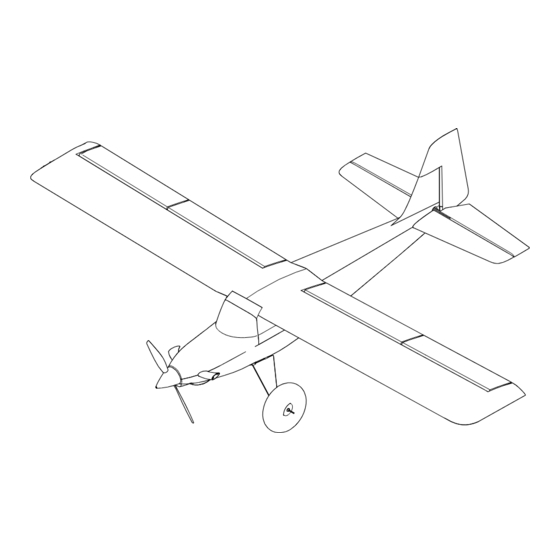
Turbo Timber SWS 2.0m
Scan the QR code and select the Manuals and Support quick links from the product page for
Scannen Sie den QR-Code und wählen Sie auf der Produktseite die Quicklinks Handbücher
und Unterstützung, um die aktuellsten informationen zu Handbücher.
Scannez le code QR et sélectionnez les liens rapides Manuals and Support sur la page du
produit pour obtenir les informations les plus récentes sur le manuel.
Scannerizzare il codice QR e selezionare i Link veloci Manuali e Supporto dalla pagina del
Instruction Manual
Bedienungsanleitung
Manuel d'utilisation
Manuale di Istruzioni
270976
Created 8/23
the most up-to-date manual information.
prodotto per le informazioni manuali più aggiornate.
EFL71750
EFL71765
Werbung
Inhaltsverzeichnis
Fehlerbehebung

Verwandte Anleitungen für Horizon Hobby E-FLITE Turbo Timber SWS 2.0m


Inhaltszusammenfassung für Horizon Hobby E-FLITE Turbo Timber SWS 2.0m
- Seite 1 Turbo Timber SWS 2.0m Scan the QR code and select the Manuals and Support quick links from the product page for the most up-to-date manual information. Scannen Sie den QR-Code und wählen Sie auf der Produktseite die Quicklinks Handbücher und Unterstützung, um die aktuellsten informationen zu Handbücher. Scannez le code QR et sélectionnez les liens rapides Manuals and Support sur la page du produit pour obtenir les informations les plus récentes sur le manuel.
-
Seite 2: Safety Precautions And Warnings
This product is not intended for use by children without direct adult supervision. Do not use with incompatible components or alter this product in any way outside of the instructions provided by Horizon Hobby, LLC. This manual contains instructions for safety, operation and maintenance. -
Seite 3: Inhaltsverzeichnis
Introduction Specifications Wingspan 80.0in (2032mm) The E-flite Turbo Timber SWS (Sport Wood Series) 2.0m is a larger and sportier ® ® Length 55.98in (1422mm) version of the incredibly popular Turbo Timber 1.5m models that also features the Without Battery: 122.3oz (3468g) benefits of lightweight, rigid and strong built-up wood construction! Weight With Recommended 6S 5000mAh battery: 148.7oz (4216g) -
Seite 4: Transmitter Setup Bnf Basic
Transmitter Setup BNF Basic Dual Rates NX Series Transmitter Setup Take first flights in Low Rate. For landings, use high rate elevator. 1. Power ON your transmitter, click on scroll wheel, roll to System Setup and click the scroll wheel. Choose yes. NOTICE: To ensure AS3X technology functions properly, do not lower rate ®... -
Seite 5: Model Assembly Arf/Bnf Basic
Model Assembly ARF/BNF Basic Removing Wrinkles ARF/BNF Basic The covering of your model may develop wrinkles during shipping and require the use of a heat gun and covering glove or covering iron with a sealing iron sock to remove them. Use caution while working around areas where the colors overlap to prevent separating the colors. - Seite 6 Recommended servo wiring From the receiver From the servo, to the wing through the wing Flaps and Two Y-Harnesses or None required for flaps Ailerons Four 6 inch extensions Two 12 inch extensions for ailerons Flap and Aileron Servo Installation 1.
- Seite 7 Horizontal and Vertical Stabilizer Installation ARF/BNF Basic 1. Remove the screw holding the filler in position using a Phillips screwdriver (PH#2). 2. Install the horizontal stabilizer, with the control horn facing down. 3. Replace the filler piece in the fuselage. 4.
- Seite 8 Landing Gear Installation ARF/BNF Basic An optional float set is available for your aircraft. When installing the floats, continue to following section, Connect the Pushrods to the Control Surfaces. The floats will be installed later in the manual. 1. Secure the axle to the landing gear using two 1/2-inch wrenches. Align the flat area on the axle toward the bottom of the aircraft.
- Seite 9 Motor and ESC Installation ARF 1. Mount the speed control inside the fuselage using a hook and loop strap. 2. Route the leads to the motor through the opening in the firewall. 3. Place a drop of threadlock on each of the M4 x 15 machine screws. Use a large Phillips screw driver (PH#2) to tighten the screws.
- Seite 10 5. Install the X mount to the back of the motor with four M3 x 3mm screws using a Phillips screwdriver (PH#1). Place a drop of threadlock on each screw before installation. 6. Mount the motor and X-mount to the firewall with four M3 x 10mm pan head machine screws with 3mm lock washers using a Phillips screwdriver (PH#1), with the motor wires extending through the hole in the firewall.
- Seite 11 Receiver Selection and Installation ARF Port Assignments AR8630T BND/PRG/SRXL2 The recommended receiver for this aircraft is the Spektrum AR8630T. If you 1 = Throttle 4 = Rudder choose to install a different receiver, ensure that it is at least a 6-channel full range 2 = Ailerons 5 = Lights receiver.
- Seite 12 Battery Tray Hook and Loop ARF/BNF Basic 1. Adhesive backed hook and loop material will not stick to bare wood. Apply a few drops of thin CA (or epoxy) to the battery tray area where you want the hook and loop material to be applied. 2.
- Seite 13 Connect the Pushrods to the Control Surfaces ARF/BNF Basic 1. Center the servo, so the servo arm is perpendicular to the servo centerline at neutral. 2. Select the shorter pushrod to connect the servo to the elevator, and the longer pushrod for the rudder..
- Seite 14 Cowling Installation ARF/BNF Basic 1. Guide the wiring for the lighting in the cowling through the hole in the firewall. 2. Slide the cowl into position, aligning the holes in the cowling with the holes in the fuselage. 3. Secure the cowling using four M2.5 x 8mm sheet metal screws and a Phillips screwdriver (PH#1).
- Seite 15 Additional Motor Cooling (Optional) ARF/BNF Basic When flying in higher temperature environments, it may be necessary to provide additional cooling for the motor. 1. Use a rotary tool with a sanding drum to remove the area indicated by the decals on the bottom of the cowling. 2.
- Seite 16 5. Draw the outline of the intake 3mm the previous lines. 6. Use a rotary tool and sanding drum to remove the material on the inside line. Remove the tape from the cowling. 7. Secure the intake using contact adhesive such as E6000. Use low-tack tape to hold the intake in position until the adhesive fully cures.
- Seite 17 Float Installation (Optional) ARF/BNF Basic 1. Assemble the floats following the instructions included with the floats. Use the mounting positions shown for the strut mounting locations. 2. Use a hobby knife with a #11 blade to expose the slots for the float mounts. 3.
- Seite 18 7. Use a drill and 2mm drill bit to drill the remaining holes. 8. Thread one of the M3 x 10mm self-tapping screws into each hole to cut threads with a Phillips screwdriver (PH#0), remove the screw. 9. Apply one drop of thin CA glue to each screw hole. Allow the CA to cure, do not use accelerator.
- Seite 19 Wing Installation ARF/BNF Basic 1. Slide the wing tube into the socket in a wing panel. 2. Slide the other wing panel on the tube. The panels will fit tightly together. 3. Connect the servo connectors from the receiver to the servos in the wings. 4.
-
Seite 20: General Binding Tips And Failsafe Bnf Basic
General Binding Tips and Failsafe BNF Basic • The included receiver has been specifically programmed for operation of this • Once bound, the receiver will retain its bind settings for that transmitter until you aircraft. Refer to the receiver manual for correct setup if the receiver is replaced. re-bind. -
Seite 21: Control Surface Centering Arf/Bnf Basic
Control Surface Centering ARF/BNF Basic 1. After assembly and transmitter setup, confirm that the control surfaces are centered using a straight edge. The model must be powered, bound to the transmitter in AS3X mode, with the throttle left at zero. When enabled, SAFE mode is active when the model is powered on. -
Seite 22: Safe® Select Switch Designation Bnf Basic
SAFE Select Switch Designation BNF Basic ® Assigning a Switch Once SAFE Select is enabled, you can choose to fly in SAFE mode full time, or assign a switch. Any switch on any channel between 5 and 9 can be used on your 1. -
Seite 23: Control Surface Direction Arf/Bnf Basic
Control Surface Direction ARF/BNF Basic Switch on the transmitter and connect the battery. Use the transmitter to operate Transmitter Command Control Surface Response the aileron, elevator, rudder and flap controls. View the aircraft from the rear when checking the control directions. Elevator 1. -
Seite 24: Propeller And Spinner Installation Arf/Bnf Basic
Propeller and Spinner Installation ARF/BNF Basic WARNING: Never install a cracked, nicked or otherwise damaged propeller or spinner. NOTICE: If the propeller is not balanced, the aircraft may vibrate, causing the stabilization system to not operate correctly and/or decrease the life of the servos. 1. -
Seite 25: Dual Rates And Control Throws Arf/Bnf Basic
Dual Rates and Control Throws ARF/BNF Basic Program your transmitter to set the rates and control throws to the values High Rate (100%) Low Rate (70%) given. These values have been tested and are a good starting point to achieve p = 45mm p = 22mm Aileron... -
Seite 26: Flying Tips And Repairs Arf/Bnf Basic
Flying Tips and Repairs ARF/BNF Basic NOTICE: If a crash is imminent, reduce the throttle and trim fully. Failure to do so Consult local laws and ordinances before choosing a flying location. could result in extra damage to the airframe, as well as damage to the ESC and Flying Field motor. -
Seite 27: In Flight Trimming Arf/Bnf Basic
In Flight Trimming ARF/BNF Basic During your first flight, trim the aircraft for level flight at 3/4 throttle with flaps up. Make small trim adjustments with your transmitter’s trim switches to straighten the aircraft’s flight path. 3 Seconds After adjusting the trim, do not touch the control sticks for 3 seconds. This allows the receiver to learn the correct settings to optimize AS3X performance. -
Seite 28: Troubleshooting Guide As3X Bnf Basic
Troubleshooting Guide AS3X BNF Basic Problem Possible Cause Solution Damaged propeller or spinner Replace propeller or spinner Imbalanced propeller Balance the propeller Motor vibration Replace parts or correctly align all parts and tighten fasteners as needed Oscillation Loose receiver Align and secure receiver in fuselage Loose aircraft controls Tighten or otherwise secure parts (servo, arm, linkage, horn and control surface) Worn parts... -
Seite 29: Replacement Parts Arf/Bnf Basic
Replacement Parts ARF/BNF Basic Part # Description Part # Description EFL71751 Fuselage EFL71762 Plastic Parts EFL71752 Wing; LH EFL71763 Decal Sheet EFL71753 Wing; RH EFL71766 Motor Mount EFL71754 Horizontal Stab EFL71767 Ldg Gear Covers EFL71755 Vertical Stab EFL71768 Spinner EFL71756 Cowling EFL71769 Wheel Set... -
Seite 30: Limited Warranty
(iii) modification of or to any part process found on our website or call Horizon to obtain a Return Merchandise of the Product, (iv) attempted service by anyone other than a Horizon Hobby authorized Authorization (RMA) number. Pack the Product securely using a shipping carton. -
Seite 31: Fcc Information
EU Manufacturer of Record: Horizon Hobby, LLC EFL Turbo TimberSWS Basic 2.0m (ELF71765): Hereby, Horizon Hobby, LLC declares that the device is in compliance with 2904 Research Road the following: EU Radio Equipment Directive 2014/53/EU, RoHS 2 Directive 2011/65/ Champaign, IL 61822 USA EU Importer of Record: EU, RoHS 3 Directive - Amending 2011/65/EU Annex II 2015/863. -
Seite 32: Sicherheitsmaßnahmen Und Warnungen
Wird das Produkt nicht sicher und umsichtig verwendet, so könnten Verletzungen oder Schäden am Produkt oder anderem Eigentum entstehen. Dieses Produkt ist nicht für den Gebrauch durch Kinder ohne direkte Aufsicht eines Erwachsenen vorgesehen. Versuchen Sie nicht, das Produkt ohne Zustimmung von Horizon Hobby, LLC zu zerlegen, mit nicht kompatiblen Komponenten zu verwenden oder beliebig zu verbessern. -
Seite 33: Einleitung
Einleitung Spezifikationen Spannweite 2023 mm (80,0 Zoll) Der E-flite Turbo Timber SWS (Sport Wood Series) 2,0 m ist eine größere und ® ® Länge 1422 mm (55,98 Zoll) sportlichere Version der unglaublich beliebten Turbo Timber 1,5 m Modelle, die Ohne Akku: 3468 g ebenfalls die Vorteile der leichten, steifen und starken Holzbauweise bietet! Gewicht Mit empfohlenem6S 5000 mAh Akku: 4216 g (148,7 oz) -
Seite 34: Einstellung Des Senders Bnf Basic
Einstellung des Senders BNF Basic Duale Geschwindigkeiten Konfiguration von Sendern der NX-Serie Für die ersten Flüge wird eine niedrige Rate empfohlen. 1. Schalten Sie Ihren Sender EIN, klicken Sie das Scrollrad an, gehen Sie auf Systemkonfiguration und klicken das Scrollrad an. Wählen Sie Ja. HINWEIS: Um sicherzustellen, dass die AS3X -Technologie einwandfrei ®... -
Seite 35: Zusammenbau Des Modells Arf/Bnf Basic
ZUsammenbau des Modells ARF/BNF Basic Falten entfernen ARF/BNF Basic Beim Versand können an der Abdeckung Ihres Modells Falten entstehen. Um diese um zu vermeiden, dass die Farben sich trennen. Indem Sie zu hohe Temperaturen zu entfernen, benötigen Sie eine Heißluftpistole und einen Schutzhandschuh oder vermeiden, beugen Sie einer Trennung der Farben vor. -
Seite 36: Empfohlene Servoverdrahtung
Empfohlene Servoverdrahtung Vom Empfänger Vom Servo zum Flügel durch den Flügel Klappen und Zwei Y-Kabelbäume oder Keine für Klappen erforderlich Querruder Vier 6“-Verlängerungen Zwei 12“-Verlängerungen für Querruder Montage von Klappe und Querruder 1. Entfernen Sie die Abdeckung für die Klappen-Servos. 2. -
Seite 37: Einbau Des Höhen- Und Seitenleitwerks Arf/Bnf Basic
Einbau des Höhen- und Seitenleitwerks ARF/BNF Basic 1. Entfernen Sie die Schraube, die den Einfüllstutzen in Position hält, mit einem Kreuzschlitzschraubendreher (PH#2). 2. Bringen Sie das Höhenleitwerk mit dem Steuerhorn nach unten an. 3. Setzen Sie den Einfüllstutzen wieder in den Rumpf ein. 4. - Seite 38 Montage des Fahrwerks ARF/BNF Basic Für Ihr Flugzeug ist ein optionaler Schwimmersatz erhältlich. Wenn Sie die Schwimmer einbauen, fahren Sie mit dem folgenden Abschnitt Verbinden der Schubstangen mit den Steuerflächen fort. Die Schwimmer werden später in der Anleitung eingebaut. 1. Fixieren Sie die Achse mit zwei 1/2“-Inbusschlüssel am Fahrwerk. Richten Sie den flachen Bereich der Achse zur Unterseite des Flugzeugs aus.
-
Seite 39: Montage Des Motors Und Des Geschwindigkeitsreglers
Montage des Motors und des Geschwindigkeitsreglers 1. Montieren Sie den Geschwindigkeitsregler im Rumpf mit Klettband. 2. Führen Sie die Leitungen durch die Öffnung im Brandschott zum Motor. 3. Tragen Sie einen Tropfen Gewindekleber auf die Maschinenschrauben M4 x 15 auf. Ziehen Sie die Schrauben mit einem großen Kreuzschlitzschraubendreher (PH#2) fest. - Seite 40 5. Befestigen Sie die X-Halterung an der Rückseite des Motors mit vier Schrauben M3 x 3 mm und einem Kreuzschlitzschraubendreher (PH#1). Vor der Montage einen Tropfen Gewindesicherung auf jede Schraube geben. 6. Befestigen Sie den Motor und die X-Halterung mit vier M3 x 10-mm- Flachkopfschrauben mit 3-mm-Sicherungsscheiben unter Verwendung eines Kreuzschlitzschraubendrehers (PH#1) am Brandschott.
-
Seite 41: Auswahl Und Montage Des Arf-Empfängers
Auswahl und Montage des ARF-Empfängers Anschlusszuweisungen AR8630T BND/PRG/SRXL2 Der empfohlene Empfänger für dieses Fluggerät ist der Spektrum AR8630T. Wird 1 = Gas 4 = Seitenruder ein anderer Empfänger montiert, sicherstellen, dass es sich dabei mindestens 2 = Querruder 5 = Beleuchtung um einen kompletten Empfänger mit 6 Kanälen handelt. -
Seite 42: Auswahl Der Schubstangen Arf/Bnf Basic
Batteriefach-Klettband ARF/BNF Basic 1. Das selbstklebende Klettband haftet nicht auf blankem Holz. Tragen Sie einige Tropfen dünnes CA (oder Epoxid) auf den Bereich des Akkufachs auf, an dem das selbstklebende Klettband angebracht werden soll. 2. Entfernen Sie das Trägermaterial und bringen Sie die Hakenseite auf dem Batteriefach an. -
Seite 43: Verbinden Der Schubstangen Mit Den Steuerflächen Arf/Bnf Basic
Verbinden der Schubstangen mit den Steuerflächen ARF/BNF Basic 1. Zentrieren Sie das Servo, so dass der Servoarm senkrecht zur Mittellinie des Servos in der Neutralstellung steht. 2. Wählen Sie das kürzere Gestänge für die Verbindung des Servos mit dem Höhenruder zu verbinden, und das längere Gestänge für das Seitenruder. 3. -
Seite 44: Montage Der Motorhaube Arf/Bnf Basic
Montage der Motorhaube ARF/BNF Basic 1. Führen Sie die Kabel für die Beleuchtung in der Motorhaube durch das Loch im Brandschott. 2. Schieben Sie die Motorhaube in Position und richten Sie die Löcher in der Motorhaube mit den Löchern im Rumpf aus. 3. -
Seite 45: Zusätzliche Motorkühlung (Optional) Arf/Bnf Basic
Zusätzliche Motorkühlung (optional) ARF/BNF Basic Wenn Sie in Umgebungen mit höheren Temperaturen fliegen, kann es erforderlich sein, den Motor zusätzlich zu kühlen. 1. Verwenden Sie ein Rotationswerkzeug mit einer Schleiftrommel, um den durch die Aufkleber gekennzeichneten Bereich auf der Unterseite der Motorhaube zu entfernen. - Seite 46 5. Zeichnen Sie den Umriss des Einlasses 3 mm von den vorherigen Linien entfernt. 6. Verwenden Sie ein rotierendes Werkzeug und eine Schleiftrommel, um das Material auf der Innenseite der Linie zu entfernen. Entfernen Sie das Band von der Motorhaube. 7.
-
Seite 47: Montieren Der Schwimmer (Optional) Arf/Bnf Basic
Montieren der Schwimmer (optional) ARF/BNF Basic 1. Montieren Sie die Schwimmer gemäß den Anweisungen, die den Schwimmern beiliegen. Verwenden Sie die gezeigten Einbaupositionen für die Befestigung der Verstrebungen. 2. Legen Sie die Schlitze für die Montage der Schwimmer mit einem Hobbymesser mit einer Nr. - Seite 48 7. Verwenden Sie eine Bohrmaschine und einen 2 mm-Bohrer zum Bohren der restlichen Löcher. 8. Drehen Sie eine der Blechschrauben M3 x 10 mm in jedes Loch, um mit einem Kreuzschlitzschraubendreher (PH#0) ein Gewinde zu schneiden, und entfernen Sie die Schraube. 9.
- Seite 49 Montage des Flügels ARF/BNF Basic 1. Scheiben Sie das Flügelrohr in die Lasche einer Tragfläche. 2. Schieben Sie die verbleibende Tragfläche auf das Rohr. Die Tragflächen werden genau zusammenpassen. 3. Verbinden Sie die Servo-Anschlüsse des Empfängers mit den Servos in den Flügeln.
-
Seite 50: Allgemeine Tipps Zur Bindung Und Failsafe Bnf Basic
Allgemeine Tipps zur Bindung und Failsafe BNF Basic • Der mitgelieferte Sender wurde speziell für den Betrieb dieses Fluggeräts • Nach erfolgter Bindung behält der Empfänger seine Bindungseinstellungen für programmiert. Nach dem Austausch des Empfängers sind die Anweisungen zur den Empfänger bei, bis eine neue Bindung erfolgt. ordnungsgemäßen Einrichtung dem Empfängerhandbuch zu entnehmen. -
Seite 51: Zentrieren Der Steuerflächen Arf/Bnf Basic
Zentrieren der Steuerflächen ARF/BNF Basic Nach dem Montieren und Einrichten des Senders überprüfen, ob die Steuerflächen mit einer geraden Kante zentriert sind. Das Modell muss im AS3X-Modus an den Sender angeschlossen werden, wobei das Gas bei Null bleibt. Wenn der SAFE- Modus aktiviert ist, ist er beim Einschalten des Modells aktiv. -
Seite 52: Schalterbelegung Von Safe ® Select Bnf Basic
Schalterbelegung von SAFE Select BNF Basic ® Zuweisen eines Schalters Sobald SAFE Select aktiviert ist, können Sie sich dafür entscheiden, Vollzeit im SAFE-Modus zu fliegen, oder einen Schalter zuweisen. Jeder Schalter auf jedem 1. Schalten Sie den Sender ein. Kanal zwischen 5 und 9 lässt sich auf Ihrem Sender verwenden. 2. -
Seite 53: Richtung Der Steuerfläche Arf/Bnf Basic
Richtung der Steuerfläche ARF/BNF Basic Den Sender einschalten und den Akku anschließen. Den Sender zum Steuern der Sendersteuerung Reaktion der Steueroberflächen Querruder-, Höhenruder- und Seitenrudersteuerungen verwenden. Beim Prüfen der Steuerungsrichtungen das Fluggerät von hinten ansehen. Die BNF Basic-Version dieses Modells verfügt über eine integrierte Ruder-Querruder- Mischung. -
Seite 54: Montage Von Propeller Und Spinner Arf/Bnf Basic
Montage von Propeller und Spinner ARF/BNF Basic WARNUNG: Niemals einen rissigen, schartigen oder anderweitig beschädigten Propeller oder Spinner montieren. HINWEIS: Ist der Propeller nicht ausbalanciert, kann das Flugzeug vibrieren, wodurch das Stabilisierungssystem nicht richtig funktioniert und/oder die Lebensdauer der Servos verkürzt wird. 1. -
Seite 55: Duale Geschwindigkeiten Und Ruderausschlag Arf/Bnf Basic
Duale Geschwindigkeiten und Ruderausschlag ARF/BNF Basic Den Sender programmieren, um die Geschwindigkeiten und Ruderausschläge Niedrige Geschwindigkeit entsprechend Ihrem Erfahrungsstand einzurichten. Diese Werte wurden Hohe Geschwindigkeit (70%) (100%) getestet und sind ein guter Ausgangspunkt, um einen erfolgreichen ersten Flug p = 45mm p = 22mm durchzuführen. -
Seite 56: Flugtipps Und Reparaturen Arf/Bnf Basic
Flugtipps und Reparaturen ARF/BNF Basic HINWEIS: Bei Einsatz der Landeklappen ist ein Höhenruder nach unten / Beachten Sie lokale Vorschriften und Gesetze bevor Sie sich einen Platz zumFliegen suchen. Landeklappenmischer erforderlich. Ein nicht beachten kann zu Kontrollverlust oder einem Absturz führen. Das Flugfeld HINWEIS: Sollte ein Absturz oder Crash bevorstehen reduzieren Sie das Gas und Wählen Sie zum Fliegen immer eine weite und offenen Fläche. -
Seite 57: Tipps Für Das Fliegen Mit Safe Select Bnf Basic
Tipps für das Fliegen mit SAFE Select BNF Basic Unterschiede zwischen den Modi SAFE Select und AS3X Wenn das Flugzeug im SAFE Select-Modus fliegt, kehrt es in den Horizontalflug zurück, wenn sich die Querruder- und Höhenrudersteuerung auf Neutral befinden. Dieser Abschnitt ist grundsätzlich präzise, berücksichtigt aber nicht die Mit der Querruder- oder Höhenrudersteuerung kann bewirkt werden, dass das Fluggeschwindigkeit, den Ladezustand der Batterie und andere einschränkende Flugzeug sich neigt, steigt oder in einen Sturzflug übergeht. -
Seite 58: Anleitung Zur As3X Fehlerbehebung Bnf Basic
Anleitung zur AS3X Fehlerbehebung BNF Basic Problem Mögliche Ursache Lösung Geschwindigkeit zu hoch Reduzieren Sie die Geschwindigkeit Beschädigter Propeller oder Spinner Ersetzen Sie den Propeller oder Spinner Propeller nicht gewuchtet Wuchten Sie den Propeller. Stellen Sie den Gainwert passend zu den Flugbedingungen ein (Wind,Drift, lokale Geänderte Flugbedingungen Bedingungen Luftfeuchtigkeit, Temperatur etc..) Motorvibrationen... -
Seite 59: Ersatzteile Arf/Bnf Basic
Ersatzteile ARF/BNF Basic Teile-Nr. Beschreibung Teile-Nr. Beschreibung EFL71751 Rumpf EFL71762 Kunststoffteile EFL71752 Flügel; links EFL71763 Dekorbogen EFL71753 Flügel; rechts EFL71766 Motorhalterung EFL71754 Höhenflosse EFL71767 Fahrwerkabdeckungen EFL71755 Seitenleitwerk EFL71768 Spinner EFL71756 Motorhaube EFL71769 Reifensatz EFL71757 Windschutzscheibe-Abdeckung EFL71770 LED-Licht-Satz EFL71758 Fahrwerk EFLP71764 Propeller;... -
Seite 60: Haftungsbeschränkung
Garantiezeitraum führen. Dieses Produkt ist nicht für den Gebrauch durch Kinder ohne die Aufsicht Exklusive Garantie Horizon Hobby LLC (Horizon) garantiert, dass dasgekaufte Produkt eines Erziehungsberechtigten vorgesehen. Die Anleitung enthält Sicherheitshinweise frei von Material- und Montagefehlern ist. Der Garantiezeitraum entspricht den und Vorschriften sowie Hinweise für die Wartung und den Betrieb des Produktes. -
Seite 61: Garantie Und Service Kontaktinformationen
2904 Research Road / EU; RoHS 3-Richtlinie - Änderung 2011/65 / EU-Anhang II 2015/863. Champaign, IL 61822 USA EFL Turbo Timber SWS 2.0m PNP (EFL71750): Hiermit erklärt Horizon Hobby, Offizieller EU-Importeur: LLC, dass das Gerät den folgenden Richtlinien entspricht:EU-Richtlinie über Horizon Hobby, GmbH elektromagnetische Verträglichkeit 2014/30/EU;... -
Seite 62: Précautions Et Avertissements Liés À La Sécurité
REMARQUE La totalité des instructions, garanties et autres documents est sujette à modification à la seule discrétion d’Horizon Hobby, LLC. Pour obtenir la documentation à jour de ce produit, veuillez consulter le site www.horizonhobby.com ou towerhobbies.com et cliquez sur l’onglet de support du produit. -
Seite 63: Outils Nécessaires
Introduction Spécifications Envergure 2032 mm (80,0 po) L’E-flite Turbo Timber SWS (Sport Wood Series) 2,0 m est une version plus ® ® d'aile grande et plus sportive du modèle très populaire Turbo Timber 1,5 m, et présente Longueur 1422 mm (55,98 po) également les avantages d’une construction en bois légère, rigide et solide ! Sans batterie : 3468 g Poids Avec batterie 5000 mAh 6S recommandée : 4216 g (148,7 oz) -
Seite 64: Configuration De L'émetteur Bnf Basic
Configuration de l’émetteur BNF Basic Double débattement Configuration d’un émetteur de la série NX Un faible débattement est recommandé pour les vols initiaux. 1. Mettez l’émetteur en marche, cliquez sur la molette, allez à Configuration du système et cliquez sur la molette. Choisissez yes (oui). REMARQUE : pour vous assurer que la technologie AS3X ®... -
Seite 65: Assemblage Du Modèle Arf/Bnf Basic
Assemblage du modèle ARF/BNF Basic Retrait des faux-plis ARF/BNF Basic Des faux-plis peuvent se former sur l’entoilage de votre modèle lors du transport. Ils nécessitent l’utilisation d’un pistolet thermique et de gants ou de fer d’entoilage avec une douille en fer scellante pour les retirer. Faites attention lorsque vous travaillez autour des zones où... - Seite 66 Câblage recommandé pour les servos Du récepteur Du servo à l’aile dans l’aile Volets et Deux faisceaux en Y ou Aucune pour les volets ailerons quatre rallonges de 6 po Deux rallonges de 12 po pour les ailerons Installation des servos d’aileron et de volet 1.
- Seite 67 Installation des stabilisateurs horizontaux et verticaux ARF/BNF Basic 1. Retirez la vis qui maintient le dispositif de remplissage en position à l’aide d’un tournevis cruciforme (PH n° 2). 2. Installez le stabilisateur horizontal avec le guignol de commande orienté vers le bas. 3.
- Seite 68 Installation du train d’atterrissage ARF/BNF Basic Un ensemble flotteurs est disponible en option pour votre appareil. Lors de l’installation des flotteurs, passez à la section suivante Raccorder les barres de liaison aux gouvernes. Les flotteurs sont installés plus loin dans le manuel. 1.
- Seite 69 Installation du moteur et du variateur ESC ARF 1. Montez le variateur de vitesse dans le fuselage à l’aide d’une bande velcro. 2. Acheminez les fils jusqu’au moteur à travers l’ouverture dans le pare-feu. 3. Appliquez une goutte de frein-filet sur chacune des vis mécaniques M4 x 15. Utilisez un grand tournevis cruciforme (PH n° 2) pour serrer les vis.
- Seite 70 5. Installez le support en X à l’arrière du moteur à l’aide de quatre vis M3 x 3 mm et d’un tournevis cruciforme (PH n° 1). Appliquez une goutte de frein-filet sur chaque vis avant l’installation. 6. Montez le moteur et le support en X sur le pare-feu à l’aide de quatre vis mécaniques à...
- Seite 71 Sélection et installation du récepteur ARF Attribution des ports du récepteur AR8630T BND/PRG/SRXL2 Le récepteur recommandé pour cet appareil est le Spektrum AR8630T. Si vous 1 = Gaz 4 = Gouverne de direction souhaitez installer un récepteur différent, assurez-vous qu’il s’agit au moins d’un 2 = Ailerons 5 = Éclairages récepteur à...
- Seite 72 Bande velcro du support de batterie ARF/BNF Basic 1. La bande velcro à support adhésif ne colle pas au bois nu. Appliquez quelques gouttes de colle CA (ou d’époxy) sur la zone du support de batterie où vous souhaitez appliquer la bande velcro. 2.
- Seite 73 Raccorder les barres de liaison aux gouvernes ARF/BNF Basic 1. Centrez le servo de manière à ce que le bras de servo soit perpendiculaire à la ligne de centre du servo en position neutre. 2. Sélectionnez la barre de liaison la plus courte pour brancher le servo à la gouverne de profondeur, et la barre la plus longue pour la gouverne de direction.
- Seite 74 Installation du capot ARF/BNF Basic 1. Faites passer le câblage de l’éclairage dans le capot par le trou du pare-feu. 2. Faites glisser le capot en position, en alignant les trous du capot sur les trous du fuselage. 3. Fixez le capot à l’aide de quatre vis à tôle M2,5 x 8 mm et d’un tournevis cruciforme (PH n° 1).
- Seite 75 Refroidissement supplémentaire du moteur (faculta- tif) ARF/BNF Basic En cas de vol dans des environnements aux températures élevées, il peut être nécessaire de prévoir un refroidissement supplémentaire pour le moteur. 1. À l’aide d’un outil rotatif muni d’un rouleau à poncer, retirez la zone indiquée par les autocollants sur la partie inférieure du capot.
- Seite 76 5. Dessinez le contour de l’admission à 3 mm des lignes précédentes. 6. À l’aide d’un outil rotatif et un rouleau à poncer, retirez le matériau sur la ligne intérieure. Retirez le ruban du capot. 7. Fixez l’admission à l’aide d’un adhésif de contact tel que E6000. À l’aide de ruban adhésif à...
- Seite 77 Installation des flotteurs (facultatif) ARF/BNF Basic 1. Assemblez les flotteurs en suivant les instructions fournies avec ceux-ci. Utilisez les positions de montage indiquées pour les emplacements de montage des haubans. 2. À l’aide d’un cutter avec une lame n° 11, exposez les fentes des supports de flotteur.
- Seite 78 7. À l’aide d’une perceuse et d’un foret de 2 mm, percez les trous restants. 8. Vissez une des vis autotaraudeuses M3 x 10 mm dans chaque trou pour découper les filets à l’aide d’un tournevis cruciforme (PH n° 0), puis retirez la vis.
- Seite 79 Installation des ailes ARF/BNF Basic 1. Faites glisser le tube d’aile dans la cavité d’un panneau d’aile. 2. Faites glisser l’autre panneau d’aile sur le tube. Les panneaux s’emboîtent les uns dans les autres. 3. Branchez les connecteurs de servo du récepteur aux servos des ailes. 4.
-
Seite 80: Conseils Généraux Pour L'affectation Et Sécurité Intégrée Bnf Basic
Conseils généraux pour l’affectation et sécurité intégrée BNF Basic • Le récepteur inclus a été spécifiquement programmé pour être utilisé avec • Une fois affecté, le récepteur conservera ses réglages d’affectation pour cet cet appareil. Reportez-vous au manuel du récepteur pour la configuration émetteur jusqu’à... -
Seite 81: Centrage Des Gouvernes Arf/Bnf Basic
Centrage des gouvernes ARF/BNF Basic Après le montage et la configuration de l’émetteur, vérifiez que les gouvernes sont bien centrées à l’aide d’une règle. Le modèle doit être sous tension et affecté à l’émetteur en mode AS3X, avec les gaz laissés à zéro. Lorsqu’il est activé, le mode SAFE est actif lorsque le modèle est mis sous tension. -
Seite 82: Désignation Du Commutateur Safe ® Select Bnf Basic
Désignation du commutateur SAFE Select BNF Basic ® Attribution d’un commutateur Une fois SAFE Select activé, vous pouvez choisir de voler continuellement en mode SAFE ou d’attribuer la fonction à un commutateur. N’importe quel commutateur sur 1. Mettez l’émetteur en marche. n’importe quel canal entre 5 et 9 peut être utilisé... -
Seite 83: Direction Des Gouvernes Arf/Bnf Basic
Direction des gouvernes ARF/BNF Basic Allumez l’émetteur et raccordez la batterie. Utilisez l’émetteur pour commander Commande de Réponse des gouvernes l’aileron, la gouverne de profondeur et la gouverne de direction. Regardez l’appareil l’émetteur de l’arrière pour vérifier les directions de commande. La version BNF Basic de ce modèle a un mixage gouvernail-aileron intégré, lorsque les ailerons sont déviés, le gouvernail se déplace. -
Seite 84: Installation De L'hélice Et Du Cône Arf/Bnf Basic
Installation de l’hélice et du cône ARF/BNF Basic AVERTISSEMENT : n’installez jamais un cône ou une hélice fissuré, ébréché ou endommagé de quelque manière que ce soit. REMARQUE : si l’hélice n’est pas équilibrée, l’appareil peut vibrer, ce qui peut entraîner un dysfonctionnement du système de stabilisation et/ou une durée de vie réduite des servos. -
Seite 85: Double Débattement Et Coudes De Commande Arf/Bnf Basic
Double débattement et coudes de commande ARF/BNF Basic Programmez votre émetteur pour configurer les débattements et les coudes de grand débattement (100%) petit débattement (70%) commande selon votre niveau d’expérience. Ces valeurs ont été testées et sont un p = 45mm p = 22mm Aileron bon point de départ pour réussir à... -
Seite 86: Conseils De Vol Et Réparations Arf/Bnf Basic
Conseils de vol et réparations ARF/BNF Basic Consultez les lois et règlements locaux avant de choisir un emplacement pour faire suffisamment ralenti pour éviter d’érafler les extrémités des ailes. voler votre avion. REMARQUE: Quand vous utilisez les volets sur ce modèle, un mixage à la Zone de vol profondeur est requis. -
Seite 87: Conseils De Vol En Mode Safe Select Bnf Basic
Conseils de vol en mode SAFE Select BNF Basic Différences entre les modes SAFE Select et AS3X Lors d’un vol en mode SAFE Select, l’appareil retourne en vol en palier à chaque fois que les commandes d’aileron et de gouverne de profondeur sont en position Cette section est généralement précise, mais ne tient pas compte de la vitesse de neutre. -
Seite 88: Guide De Dépannage As3X Bnf Basic
Guide de dépannage AS3X BNF Basic Problème Cause possible Solution Vitesse de vol supérieure aux vitesses recommandées Réduire la vitesse de vol Hélice ou cône endommagés Remplacer l’hélice ou le cône Déséquilibre de l’hélice Équilibrer ou remplacer l’hélice Ajuster le gain aux conditions de vol ( vent, courants d’air ascendants, conditions de Variation des conditions de vol terrain: altitude, humidité, température, etc.) Vibration du moteur... -
Seite 89: Pièces De Rechange Arf/Bnf Basic
Problème Cause possible Solution La gouverne, bras de commande, tringlerie ou servo Remplacer ou réparer les pièces endommagées et régler les commandes endommagé Câblage endommagé ou connexions lâches Contrôler les câbles et les connexions, connecter ou remplacer si besoin L’émetteur n’est pas affecté correctement ou il y a eu La gouverne ne bouge pas Effectuer une nouvelle affectation ou sélecter le modèle correct dans l’émetteur sélection d’un modèle incorrect... -
Seite 90: Garantie Et Réparations
Durée de la garantie Indications relatives à la sécurité Garantie exclusive - Horizon Hobby, LLC (Horizon) garantit que le Produit acheté (le Ceci est un produit de loisirs perfectionné et non un jouet. Il doit être utilisé avec « Produit ») sera exempt de défauts matériels et de fabrication à sa date d’achat précaution et bon sens et nécessite quelques aptitudes mécaniques ainsi que... -
Seite 91: Informations Ic
Importateur officiel de l’UE: Modifiant 2011/65/UE Annexe II 2015/863. Horizon Hobby, GmbH EFL Turbo Timber SWS 2.0m PNP (EFL71750): Par la présente, Horizon Hobby, Hanskampring 9 LLC déclare que cet appareil est conforme aux directives suivantes : Directive CEM 22885 Barsbüttel Germany 2014/30/UE ;... -
Seite 92: Precauzioni E Avvertenze Sulla Sicurezza
AVVISO Tutte le istruzioni, le garanzie e gli altri documenti pertinenti sono soggetti a cambiamenti a totale discrezione di Horizon Hobby, LLC. Per una documentazione aggiornata sul prodotto, visitare il sito horizonhobby.com o towerhobbies.com e fare clic sulla sezione Support del prodotto. -
Seite 93: Utensili Necessari
Introduzione Specifiche Apertura 2032 mm L’E-flite Turbo Timber SWS (Sport Wood Series) 2.0m è una versione più grande ® ® alare e sportiva dei modelli Turbo Timber 1.5m, incredibilmente popolari, che presenta Lunghezza 1422 mm anche i vantaggi della costruzione in legno leggero, rigido e resistente! Senza batteria: 3468 g Peso Con batteria consigliata 6S 5000 mAh: 4216 g... -
Seite 94: Impostazione Della Trasmittente (Bnf Basic)
Impostazione della trasmittente (BNF Basic) Dual Rate Impostazione delle trasmittenti serie NX Si consiglia una riduzione di corsa corta per i primi voli. 1. Accendere la trasmittente, premere la rotella di scorrimento, scorrere fino a System Setup (Impostazione sistema) e premere di nuovo sulla rotella. AVVISO: per garantire il corretto funzionamento della tecnologia AS3X , non ®... -
Seite 95: Modello Di Montaggio Arf/Bnf Basic
Modello di montaggio ARF/BNF Basic Eliminare le rughe ARF/BNF Basic Il rivestimento del modello può formare delle grinze durante la spedizione e richiedere l'uso di una pistola termica e di un guanto di copertura o di un ferro da stiro con una calza da stiro sigillante per rimuoverle. Prestare attenzione quando si lavora attorno ad aree con sovrapposizione di colori per evitarne il distacco. - Seite 96 Cablaggio servo consigliato Dal ricevitore Dal servo all’ala attraverso l’ala Flap e Due cablaggi a Y o Nessuna richiesta per i flap alettoni quattro prolunghe da 6 Due prolunghe da 12 pollici per gli pollici alettoni Installazione servo dell’alettone e flap 1.
- Seite 97 Installazione degli stabilizzatori orizzontali e verticali ARF/BNF Basic 1. Rimuovere la vite che tiene in posizione il bocchettone di riempimento con un cacciavite a croce (PH#2). 2. Installare lo stabilizzatore orizzontale, con la squadretta di comando rivolta verso il basso. 3.
- Seite 98 Installazione del carrello di atterraggio ARF/BNF Basic Per il vostro aereo è disponibile un set di galleggianti opzionale. Quando si installano i galleggianti, continuare con la sezione seguente, Collegare le aste di spinta alle superfici di controllo. I galleggianti saranno installati più avanti nel manuale.
- Seite 99 Installazione del motore e dell'ESC ARF 1. Montare il controllo della velocità all'interno della fusoliera utilizzando una cinghia con gancio e anello. 2. Far passare i cavi del motore attraverso l'apertura nel firewall. 3. Applicare una goccia di frenafiletti su ognuna delle viti M4 x 15. Utilizzare un cacciavite Phillips grande (PH#2) per serrare le viti.
- Seite 100 5. Installare il supporto a X sul retro del motore con quattro viti M3 x 3 mm utilizzando un cacciavite Phillips (PH#1). Applicare una goccia di frenafiletti su ogni vite prima di installarla. 6. Montare il motore e il supporto a X sul firewall con quattro viti a testa cilindrica M3 x 10 mm con rondelle di sicurezza da 3 mm utilizzando un cacciavite Phillips (PH#1), con i fili del motore che passano attraverso il foro nel firewall.
-
Seite 101: Installazione Dell'adattatore Per Eliche Arf/Bnf Basic
Scelta e installazione del ricevitore ARF Assegnazione porte AR8630T BND/PRG/SRXL2 Per questo modello si consiglia un ricevitore Spektrum AR8630T. Se si sceglie 1 = Manetta 4 = Timone di installare un ricevitore diverso, assicurarsi che si tratti di un modello a piena 2 = Alettoni 5 = Luci portata con almeno 6 canali. - Seite 102 Vassoio batteria con gancio e anello ARF/BNF Basic 1. Il materiale adesivo con ganci e anelli non si attacca al legno nudo. Applicare alcune gocce di CA (o epossidica) sottile nell'area del vassoio della batteria dove si desidera applicare il materiale con ganci e occhielli. 2.
- Seite 103 Collegare le aste di spinta alle superfici di controllo ARF/BNF di base 1. Centrare il servo, in modo che il braccio del servo sia perpendicolare alla linea centrale del servo in posizione neutra. 2. Selezionare l'asta di spinta più corta per collegare il servo all'elevatore e quella più...
- Seite 104 Installazione della cappottatura ARF/BNF Basic 1. Far passare il cablaggio dell'illuminazione nella cappottatura attraverso il foro nel firewall. 2. Far scorrere la cappottatura in posizione, allineando i fori della cappottatura con quelli della fusoliera. 3. Fissare la cappottatura con quattro viti per lamiera M2,5 x 8 mm e un cacciavite Phillips (PH#1).
- Seite 105 Raffreddamento supplementare del motore (opziona- le) ARF/BNF Basic Quando si vola in ambienti con temperature elevate, può essere necessario prevedere un raffreddamento supplementare per il motore. 1. Utilizzare un utensile rotante con un tamburo di levigatura per rimuovere l'area indicata dalle decalcomanie sul fondo della cappottatura. 2.
- Seite 106 5. Disegnare il contorno della presa d'aria a 3 mm dalle linee precedenti. 6. Utilizzare un utensile rotante e un tamburo di levigatura per rimuovere il materiale sulla linea interna. Rimuovere il nastro dalla cappottatura. 7. Fissare la presa utilizzando un adesivo a contatto come E6000. Utilizzare del nastro adesivo a bassa tenuta per mantenere la presa in posizione fino al completo indurimento dell'adesivo.
- Seite 107 Installazione del galleggiante (opzionale) ARF/BNF Basic 1. Assemblare i galleggianti seguendo le istruzioni fornite con i galleggianti stessi. Per le posizioni di montaggio dei puntoni, utilizzare le posizioni di montaggio indicate. 2. Utilizzare un taglierino con lama #11 per esporre le fessure per i supporti del galleggiante.
- Seite 108 7. Utilizzare un trapano e una punta da 2 mm per praticare i fori rimanenti. 8. Infilare una delle viti autofilettanti M3 x 10 mm in ciascun foro per tagliare la filettatura con un cacciavite Phillips (PH#0), quindi rimuovere la vite. 9.
- Seite 109 Installazione dell'ala ARF/BNF Basic 1. Far scorrere il tubo dell'ala nella presa di un pannello dell'ala. 2. Far scorrere l’altro pannello dell’ala sul tubo. I pannelli si incastreranno perfettamente tra loro. 3. Collegare i connettori dei servi dal ricevitore ai servi nelle ali. 4.
-
Seite 110: Consigli Generali Per Binding E Failsafe Bnf Basic
• In caso di problemi, consultare la guida alla risoluzione dei problemi o, • Il LED arancione sul ricevitore inizia a lampeggiare rapidamente se necessario, contattare il servizio di assistenza di Horizon Hobby. quando il ricevitore entra in modalità di binding. -
Seite 111: Centraggio Delle Superfici Di Controllo Arf/Bnf Basic
Centraggio delle superfici di controllo ARF/BNF Basic Dopo l'assemblaggio e la messa a punto del trasmettitore, verificare che le superfici di controllo siano centrate utilizzando un regolo. L'aeromodello deve essere alimentato, collegato al trasmettitore in modalità AS3X, con il motore lasciato a zero. -
Seite 112: Assegnazione Interruttore Safe ® Select Bnf Basic
Assegnazione interruttore SAFE Select BNF Basic ® Assegnazione di un interruttore Una volta abilitata la funzione SAFE Select, è possibile scegliere se volare in modalità SAFE non disinseribile, oppure assegnarne l’attivazione a un interruttore. 1. Accendere la trasmittente. È possibile assegnare la funzione a uno qualsiasi degli interruttori dei canali da 5 2. -
Seite 113: Direzione Della Superficie Di Controllo Arf/Bnf Basic
Direzione della superficie di controllo ARF/BNF Basic Accendere la trasmittente e collegare la batteria. Usare la trasmittente per azionare Comando trasmittente Risposta delle superfici di controllo i comandi di alettone, equilibratore e timone. Controllare il movimento delle superfici di controllo guardando il velivolo dal retro. Elevatore 1. -
Seite 114: Installazione Dell'elica E Dell'ogiva Arf/Bnf Basic
Installazione dell'elica e dell'ogiva ARF/BNF Basic AVVERTENZA: non installare mai elica o ogiva se queste appaiono incrinate, scalfite o altrimenti danneggiate. AVVISO: un’elica non bilanciata può indurre vibrazioni e impedire il corretto funzionamento del sistema di stabilizzazione e/o riducendo la vita utile dei servo. 1. -
Seite 115: Doppie Velocità E Tiri Di Controllo Arf/Bnf Basic
Doppie velocità e tiri di controllo ARF/BNF Basic Programmare la trasmittente per impostare le velocità e le limitazioni dei comandi Riduttore alto (100%) Riduttore basso (70%) in base al livello di esperienza. Tali valori sono stati verificati e sono un buon punto p = 45mm p = 22mm Alettone... -
Seite 116: Consigli Di Volo E Riparazioni Arf/Bnf Basic
Consigli di volo e riparazioni ARF/BNF Basic AVVISO: quando si usano i flap con questo aereo, è necessario avere una Prima di scegliere un posto dove volare, conviene consultare le leggi e le ordinanze locali. miscelazione con l’elevatore verso il basso. In caso contrario si potrebbe perdere il controllo e danneggiare l’aereo. -
Seite 117: Selezionare Safe Suggerimenti Per Il Volo Bnf Basic
Selezionare SAFE Suggerimenti per il volo BNF Basic Differenze tra le modalità SAFE Select e AS3X In modalità SAFE Select, il modello riprende a volare in volo livellato ogni volta che i comandi di equilibratore e alettoni sono in posizione neutra. L’azionamento di Questa sezione è... -
Seite 118: Guida Alla Risoluzione Dei Problemi As3X Bnf Basic
Guida alla risoluzione dei problemi AS3X BNF Basic Problema Possibile causa Soluzione Si vola oltre la velocità consigliata Ridurre la velocità Elica od ogiva danneggiate Sostituire l’elica o l’ogiva Elica sbilanciata Bilanciare l’elica Adeguare la sensibilità alle condizioni attuali Variazione delle condizioni di volo (vento, termiche, elevazione, umidità, temperatura, ecc.) Vibrazioni del motore Sostituire o allineare correttamente tutte le parti stringendo le relative viti... -
Seite 119: Parti Di Ricambio Arf/Bnf Basic
Problema Possibile causa Soluzione Superfici di comando, squadrette, comandi o servi Riparare o sostituire le parti danneggiate danneggiati Fili danneggiati o connessioni allentate Controllare i fili e le connessioni facendo poi le debite riparazioni Le superfici di controllo non si Trasmettitore non connesso correttamente o scelta del Scegliere il modello giusto o rifare la connessione muovono... -
Seite 120: Garanzia
Periodo di garanzia Indicazioni di sicurezza Garanzia esclusiva - Horizon Hobby, LLC (Horizon) garantisce che il prodotto acquistato Questo è un prodotto sofisticato di hobbistica e non è un giocattolo. Esso deve essere (il “Prodotto”) sarà privo di difetti relativi ai materiali e di eventuali errori di montaggio manipolato con cautela, con giudizio e richiede delle conoscenze basilari di meccanica alla data di acquisto. -
Seite 121: Dichiarazione Di Conformità Per L'unione Europea
Produttore ufficiale dell’UE: EFL Turbo Timber SWS 2.0m Basic (EFL71765): Con la presente, Horizon Hobby, LLC Horizon Hobby, LLC dichiara che il dispositivo è conforme a quanto 2904 Research Road segue: Direttiva europea sulle apparecchiature radio (RED) 2014/53/ Champaign, IL 61822 USA UE;... - Seite 124 E-flite, Avian, DSM, DSM2, DSMX, Bind-N-Fly, BNF, the BNF logo, Plug-N-Play, AS3X, SAFE, the SAFE logo, ModelMatch, IC3, EC3, and the Horizon Hobby logo are trademarks or registered trademarks of Horizon Hobby, LLC. The Spektrum trademark is used with permission of Bachmann Industries, Inc.