Herunterladen Inhalt Inhalt Diese Seite drucken
TERMOFOL TF-WIFI Mark II Benutzerhandbuch
Vorschau ausblenden Andere Handbücher für TF-WIFI Mark II:

Werbung

Verfügbare Sprachen

Verfügbare Sprachen

TERMOREGULATOR
TERMOFOL TF-WIFI
Mark II
INSTRUKCJA OBSŁUGI
I KONFIGURACJI TERMOREGULATORA
Instrukcja montażu
Installation manual
Installationsanleitung

Werbung

Inhaltsverzeichnis
loading

Inhaltszusammenfassung für TERMOFOL TF-WIFI Mark II

  • Seite 1 TERMOREGULATOR TERMOFOL TF-WIFI Mark II INSTRUKCJA OBSŁUGI I KONFIGURACJI TERMOREGULATORA Instrukcja montażu Installation manual Installationsanleitung...
  • Seite 2: Specyfikacja Techniczna

    CHARAKTERYSTYKA I DANE TECHNICZNE Dziękujemy za zakup naszego produktu. Liczymy, że będziecie Państwo zadowoleni z korzystania z termoregulatora TERMOFOL TF-WIFI Mark II. Jest to w pełni funkcjo- nalny sterownik instalacji i urządzeń grzewczych, zapewniający najwyższy komfort obsługi oraz precyzyjne i użyteczne funkcje, które pozwolą Państwu w pełni uzyskać...
  • Seite 3 INSTALACJA TERMOSTATU, POŁĄCZENIA ELEKTRYCZNE TERMOFOL TF-WIFI Mark II to nowoczesny, wyposażony w panel sterujący LED, pro- gramowalny termoregulator przeznaczony do sterowania elektrycznymi systemami grzewczymi. Termoregulator odczytuje temperaturę z wewnętrznego i zewnętrzne- go czujnika temperatury, który jest dołączony w zestawie. Funkcja Wifi oraz dedy- kowana aplikacja producenta TERMOFOL SMART umożliwia sprawowanie nadzoru...
  • Seite 4 Rys. 3 sensor Przykład umiejscowienia termoregulatora Termoregulator może być instalowa- ny w standardowej puszcze ścien- nej 86mm lub europejskiej okrągłej 60mm. Rys. 4 1. Podłącz zasilanie oraz pozostałe przewody zgodnie ze schematem podłączenia. Rys. 5 2. Przykręć blachę montażową do puszki montażowej. Rys.
  • Seite 5 Rys. 7 Przykład właściwego podłączenia termoregulatora W celu instalacji termoregulatora w puszce elektrycznej i podłączeń elektrycznych należy bardzo delikatnie (tak by nie urwać taśmy połączeniowej) otworzyć obudo- wę, zdejmując zespół wyświetlacza zgodnie z instrukcją przedstawioną na rysunku 4. Ekran należy delikatnie przesunąć w górę. (odwrotnie niż przedstawia to rys.6) Instalacja termoregulatora powinna być...
  • Seite 6 W stanie włączonego termoregulatora dotknięcie przycisku przez 3–5 sekund pozwala użytkownikowi zaprogramować harmonogram pracy termoregulatora. W stanie wyłączonego termoregulatora dotknięcie tego przycisku przez 3–5 sekund pozwala konfigurować ustawienia zaawansowane B. W stanie włączonego termoregulatora krótkie naciśnięcie daje możliwość ustawie- nia godziny i dnia tygodnia. Natomiast dotknięcie przez 3-5 sekund pozwala akty- wować...
  • Seite 7 IKONY WYŚWIETLACZA – SPECYFIKACJA ikona potwierdzająca pracę ter- AUTO brak połączenia Wifi mostatu w trybie automatycznego harmonogramu AUTO tryb manualny tymczasowy tryb manualny tryb wakacyjny połączenie Wifi wyłączenie ogrzewania, spo- wodowane wysoką tempera- zegar turą podłogi CLOCK ikona połączenia Cloud blokada przycisków zewn.
  • Seite 8 Zakres wartości Wartość Rodzaj parametru parametru fabryczna Kalibracja czujnika –9 °C ÷ 9 °C –1 temperatury powietrza Histereza 0,5–2,5 °C 1 °C 0: blokada częściowa 1: Blokada przycisków blokada pełna 0: Urządzenie przyjmuje swój stan sprzed zaniku zasilania Funkcja pamięci stanu 1: Urządzenie pozostaje urządzenia przed zanikiem wyłączone po powrocie...
  • Seite 9 Zakres wartości Wartość Rodzaj parametru parametru fabryczna N1: tylko wewnętrzny czuj- nik temp. włączony N2: tylko zewn. czujnik temp. włączony N3: włączony wewnętrzny Wybór czujników temperatury – i zewnętrzny czujnik sposobu kontroli temperatury temperatury – utrzyma- nie zadanej temperatury powietrza z kontrolą temperatury urządzenia grzewczego Funkcja odkamieniania...
  • Seite 10 Należy wykonać pomiar rezystancji czujnika NTC. Pomiar rezystancji czujnika NTC przeprowadzamy miernikiem uniwersalnym ustawionym na pomiar rezystancji w zakresie od 20 kΩ. Pomiar rezystancji czujnika podłogowego, ma charakter kon- trolno-informacyjny i ma na celu, podobnie jak pomiar rezystancji systemu grzew- czego wykluczyć...
  • Seite 11 WYBÓR I INSTALACJA APLIKACJI Termostat współpracuje wyłącznie z sieciami WiFi 2,4 Ghz. Sterowanie termostatem odbywa się za pośrednictwem aplikacji TERMOFOL SMART dostępnej na platformy Android oraz IoS. W celu przeprowadzenia procesu podłączenia termostatu do lokalnej sieci WiFi należy pobrać na swoje urządzenie mobilne aplikację TERMOFOL SMART wykorzystując poniższe kody QR:...
  • Seite 12 . Termostat jest gotowy do połączenia z siecią WiFi. PODŁĄCZENIE TERMOSTATU W APLIKACJI Mając przygotowany termostat, uruchamiamy aplikację TERMOFOL SMART i po zalogowaniu do aplikacji na ekranie głównym wybieramy funkcję dodaj urządzenie. Na kolejnym ekranie należy wybrać ikonę termostat, oraz na kolejnym ekranie zaznaczyć opcję...
  • Seite 13 Potwierdza to dodatkowo, że cały proces podłączenia przebiegł pomyślnie i możemy przejść do sterowania i konfigurowania termostatu z udziałem aplikacji. PODŁĄCZENIE TERMOSTATU DO APLIKACJI – SPOSÓB 2 Podczas włączonego termoregulatora naciśnij i przytrzymaj SET + OK aż pojawi się migający symbol .
  • Seite 14 Należy zaznaczyć „Potwierdź wolne mruganie wyświetlacza” i nacisnąć „Next”. W kolejnym eta- pie wpisz nazwę swojej sieci oraz hasło. Naciśnij ‘’Następny’’ i „Podłącz teraz”. Wybierz sygnał Wifi „Smartlife-XXXX”. Należy ponownie wrócić do aplikacji i naciśnij „Connect”. Aplikacja połą- czy się automatycznie. Może to potrwać do 90 sekund. Po dodaniu urządzenia można edytować...
  • Seite 15 ZMIANA KONFIGURACJI CZUJNIKÓW TEMPERATURY Po wybraniu przycisku pojawia się nam ekran „Setting”. Zawiera on listę ustawień i funkcji zaawansowanych ułożonych w formie poziomych belek, opisanych nazwą danej funkcji wraz z informacją o bieżącej wartości każdej funkcji, prezentowaną przy prawej krawędzi danego wiersza.
  • Seite 16 PROGRAMOWANIE HARMONOGRAMU PRACY AUTOMATYCZNEJ Po wybraniu przycisku pojawia się nam ekran „Setting”. Wybieramy wiersz „Program type” ustawiając rodzaj harmonogramu 5+2/6+1/7 dniowego zatwierdzając wybór przyciskiem „Done”. Po czym wybieramy funkcję „Weekly program setting” i definiujemy wartości tempe- ratur dla wybranych okresów doby, modyfikując dowolnie zarówno wartość temperatury jak i godziny graniczne definiujące początek i koniec kolejnych okresów, dla wybranego schematu tygodniowego.
  • Seite 17: Karta Gwarancyjna

    KARTA GWARANCYJNA MIEJSCE INSTALACJI DANE INSTALATORA Nazwa firmy Imię i Nazwisko Adres (ulica, nr) Miejscowość Telefon Data Podpis instalatora Pieczątka instalatora www.termofol.pl biuro@termofol.pl +48 (12) 376 86 00...
  • Seite 18 THERMOREGULATOR TERMOFOL TF-WIFI Mark II OPERATING AND CONFIGURATION MANUAL OF THERMOREGULATOR Installation manual...
  • Seite 19: Characteristics And Technical Data

    CHARACTERISTICS AND TECHNICAL DATA Thank you for purchasing our product. We hope that you will enjoy using the TERMOFOL TF-WI-FI Mark II thermoregulator. It is a fully functional controller of installations and heating devices providing the highest comfort of use, as well as precise and useful functions that will allow you to fully control the climate in your rooms.
  • Seite 20 Wi-Fi function and the manufacturer’s dedicated TERMOFOL SMART application enable to supervi- se the heating installation in the mobile manner. Prior to its installation, disassem- bly, cleaning, inspection or change of the configuration, always disconnect the ther- moregulator from the power source, e.g., by switching off the power line in the...
  • Seite 21 Fig. 3 sensor Example of thermoregulator location Thermoregulator can be installed in a standard 86mm wall junction box or in a 60mm European round junction box. Fig. 4 1. Connect the power supply and other wires as shown in the wiring diagram.
  • Seite 22 Fig. 7 Example of correct connection of a thermoregulator For the purpose installation of the thermoregulator, in the junction box and making the electric connections, you should open its housing very gently (so as not to bre- ak the connection tape) by removing the display assembly according as shown in Figure 2.
  • Seite 23 When the thermoregulator ON, touching the button for 3-5 seconds enables the user to program the thermoregulator operating schedule. When the thermoregulator OFF, touching the button for 3-5 seconds enab- les the user to configure the advanced B settings. When the thermostat is ON, a short press enables the user to set the time and day of the week.
  • Seite 24 DISPLAY ICONS – SPECIFICATION icon confirming thermo- AUTO no Wi-fi connection stat operation in the automatic schedule mode AUTO manual mode temporary manual mode holiday mode Wi-fi switching off the heating, caused by high temperature clock of floor CLOCK icon of Cloud connection button lock external temperature sensor SETTING THE OPERATING SCHEDULE...
  • Seite 25 Range of parameter Type of function / parameter Factory value value / function option Calibration of air temperature –9 °C ÷ 9 °C –1 sensor Hysteresis 0,5–2,5 °C 1 °C 0: partial locking / 1: full Locking of buttons locking 0: Device restores its state prior to a power failure Memory function of device status...
  • Seite 26 Range of parameter Type of function / parameter Factory value value / function option N1: only built-in tempera- ture sensor is on N2: only external tempera- ture sensor is on Selection of temperature sensors – N3: built-in and external method of controlling the tempe- temperature sensor are on rature –...
  • Seite 27 The resistance of the NTC sensor is measured with a universal meter set to measure resistance in the range from 20 kΩ. The measurement of the floor sensor resistance is of control and informational nature, and its purpose is, similarly to the measure- ment of the heating system resistance, to exclude damage of the connection wire (e.g., its tearing when pulling it into the conduit) or the NTC sensor itself.
  • Seite 28: Registration Of An Account In The Application

    The thermostat works exclusively with Wi-Fi 2.4 Ghz networks. The thermostat is controlled by the TERMOFOL SMART application available for Android and iOS platforms. For the purpose of the performance of the process of connecting the thermostat to the local Wi-Fi network, do-...
  • Seite 29: Connecting The Thermostat In The Application

    . The thermostat is ready to connect to the Wi-Fi network. CONNECTING THE THERMOSTAT IN THE APPLICATION Having prepared the thermostat, launch the TERMOFOL SMART application and upon logging into the application on the main screen, select the function ‘add device’.
  • Seite 30 This further confirms that the entire connection process has been successful and you can pro- ceed to control and configure the thermostat with the application. CONNECTING THE THERMOSTAT TO THE APPLICATION – METHOD 2 With the thermostat switched on, press and hold SET + OK until the flashing symbol .
  • Seite 31 Select ‚Confirm slow blinking display’ and press ‚Next’. In the next step, enter your network name and password. Press ‚Next’ and ‚Connect now’. Select the ‚Smartlife-XXXX’ Wi-Fi signal. Go back to the application and press ‚Connect’. The application will connect automatically. This may take up to 90 seconds.
  • Seite 32 CHANGING THE CONFIGURATION OF THE TEMPERATURE SENSORS Upon selecting the button the ‚Setting’ screen appears. It contains a list of settings and advanced functions arranged in the form of horizontal bars, described with the name of a gi- ven function and information about the current value of each function, presented at the right edge of a given row.
  • Seite 33 PROGRAMMING OF THE AUTOMATIC OPERATION SCHEDULE Upon selecting the button , the ‚Setting’ screen will appear. Select the ‚Program type’ row and set the type of 5+2/6+1/7-day schedule while confirming your choice with ‚Done’. Then, select the ‚Weekly program setting’ function and define temperature values for selected pe- riods of a day, freely modifying both the temperature value and the time limits defining the beginning and end of subsequent periods, for the selected weekly schedule.
  • Seite 34: Warranty Card

    WARRANTY CARD PLACE OF INSTALLATION FITTER’S DETAILS Name of company Forename and surname Address (street, no.) Postal Locality code Tel. Date Fitter’s signature Fitter’s stamp www.termofol.com biuro@termofol.pl +48 (12) 376 86 00...
  • Seite 35 THERMOREGULATOR TERMOFOL TF-WIFI Mark II BENUTZERHANDBUCH UND KONFIGURATION DES THERMOREGULATORS Installationsanleitung...
  • Seite 36: Eigenschaften Und Technische Daten

    EIGENSCHAFTEN UND TECHNISCHE DATEN Vielen Dank für den Kauf unseres Produkts. Wir hoffen, dass Sie mit der Verwen- dung des Thermoregulators TERMOFOL TF-WIFI Mark II zufrieden sein werden. Es ist ein voll funktionsfähiger Regler für Heizungsanlagen und -geräte, der höchsten Bedienkomfort sowie präzise und nützliche Funktionen gewährleistet, mit denen Sie...
  • Seite 37: Installation Des Thermostats, Elektrische Anschlüsse

    INSTALLATION DES THERMOSTATS, ELEKTRISCHE ANSCHLÜSSE TERMOFOL TF-WIFI Mark II ist ein moderner, programmierbarer Thermoregler mit LED-Bedienfeld, der zur Steuerung elektrischer Heizsysteme entwickelt wur- de. Der Thermoregulator liest die Temperatur von den internen und externen Temperatursensoren, die im Set enthalten sind. Die Wifi-Funktion und die spe- zielle Anwendung des Herstellers TERMOFOL SMART ermöglichen es Ihnen, die...
  • Seite 38 Abb. 3 sensor Ein Beispiel für den Standort eines Thermoreglers Der Temperaturregler kann in einer standardmäßigen 86-mm-Wanddo- se oder einer europäischen runden 60-mm-Dose installiert werden. Abb. 4 1. Schließen Sie die Stromversor- gung und andere Kabel gemäß dem Anschlussplan an. Abb.
  • Seite 39: Steuerung - Beschreibung Der Steuertasten

    Abb. 7 Ein Beispiel für eine ordnungsgemäße Thermoregulator-Verbindung Um den Thermoregulator im Schaltkasten und den elektrischen Anschlüssen zu in- stallieren, öffnen Sie das Gehäuse sehr vorsichtig (um das Verbindungsband nicht zu beschädigen) und entfernen Sie die Anzeigeeinheit gemäß den Anweisungen in Abbildung 4.
  • Seite 40 Wenn der Thermoregulator eingeschaltet ist, kann der Benutzer durch Drücken der Taste für 3-5 Sekunden den Betriebsplan des Thermoregulators programmieren. Wenn der Thermoregulator ausgeschaltet ist, können Sie durch Berühren dieser Taste für 3–5 Sekunden erweiterte B-Einstellungen konfigurieren. Wenn der Thermoregulator eingeschaltet ist, können Sie durch kurzes Drücken die Uhrzeit und den Wochentag einstellen.
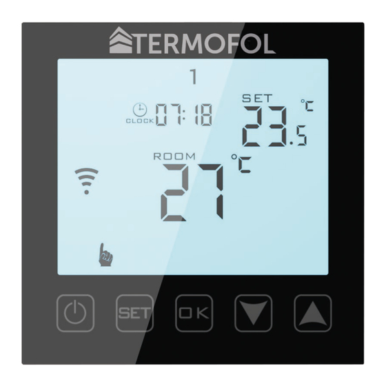
  • Seite 41: Anzeigesymbole - Spezifikation

    ANZEIGESYMBOLE – SPEZIFIKATION Symbol, das den Betrieb des Ther- AUTO keine WLAN-Verbindung mostats im automatischen Zeit- planmodus bestätigt AUTO manueller Modus temporärer manueller Modus WiFi Verbindung Urlaubsmodus Heizungsabschaltung wegen hoher Fußbodentemperatur CLOCK Cloud-Verbindungssymbol Tastensperre außen Temperatursensor EINSTELLEN DES ARBEITSPLANS Drücken Sie bei eingeschaltetem Thermoregulator die Taste für 3-5 Sekunden.
  • Seite 42 Der Bereich Nein Parametertyp Fabrikwert des Parameterwerts Kalibrierung des Lufttemperatur- –9 °C ÷ 9 °C –1 sensors Hysterese 0,5–2,5 °C 1 °C Tastensperre 0: Teilsperre 1: Vollsperre 0: Urządzenie przyjmuje 0: Das Gerät kehrt in seinen Zustand vor dem Einschal- ten zurück 1: Das Gerät bleibt nach Gerätezustandsspeicherfunktion...
  • Seite 43 Der Bereich Nein Parametertyp Fabrikwert des Parameterwerts N1: Nur interner Tempera- tursensor aktiviert N2: nur ext. Temperatur- sensor an Auswahl von Temperatursensoren N3: interner und externer – die Methode der Temperaturre- Temperatursensor einge- gelung schaltet - Beibehaltung der eingestellten Lufttempera- tur mit Temperaturrege- lung des Heizgerätes Entkalkungsfunktion (für Wasser-...
  • Seite 44 Messen Sie den Widerstand des NTC-Sensors. Die Widerstandsmessung des NTC- Fühlers führen wir mit einem universellen Messgeräte-Set zur Widerstandsmessung durch im Bereich von 20 kΩ. Die Widerstandsmessung des Bodenfühlers ist eine Kontroll- und Informationsmessung und dient, ähnlich wie die Widerstandsmes- sung der Heizungsanlage, dem Ausschluss einer Beschädigung des Anschlusskabels (z.
  • Seite 45: Auswahl Und Installation Der Anwendung

    AUSWAHL UND INSTALLATION DER ANWENDUNG Der Thermostat funktioniert nur mit 2,4-GHz-WLAN-Netzwerken. Der Thermostat wird über die TERMOFOL SMART-Anwendung gesteuert, die für Android- und IoS-Plattformen verfügbar ist. Um den Thermostat mit dem lokalen WLAN-Netzwerk zu verbinden, laden Sie die TERMO- FOL SMART-Anwendung mithilfe der folgenden QR-Codes auf Ihr Mobilgerät herunter:...
  • Seite 46 WLAN-Netzwerk zu verbinden. VERBINDEN DES THERMOSTATS IN DER APP Nachdem Sie den Thermostat vorbereitet haben, starten Sie die Anwendung TERMOFOL SMART und wählen Sie nach dem Einloggen in die Anwendung auf dem Hauptbildschirm die Funktion Gerät hinzufügen.
  • Seite 47: Anschluss Des Thermostats An Die Anwendung - Methode

    Dies bestätigt zusätzlich, dass der gesamte Verbindungsprozess erfolgreich war und wir kön- nen mit der Teilnahme der Anwendung an die Steuerung und Konfiguration des Thermostats gehen. ANSCHLUSS DES THERMOSTATS AN DIE ANWENDUNG - METHODE 2 Halten Sie bei eingeschaltetem Thermoregulator SET + OK gedrückt, bis das blinkende Symbol erscheint.
  • Seite 48 Wählen Sie „Langsames Blinken des Displays bestätigen“ und drücken Sie „We- iter“. Geben Sie im nächsten Schritt Ihren Netzwerknamen und Ihr Passwort ein. Drücken Sie „Weiter“ und „Jetzt verbinden“. Wählen Sie das WLAN-Signal „Smar- tlife-XXXX“. sollten Anwendung zurückkehren „Verbinden“ klic- ken.
  • Seite 49: Ändern Der Konfiguration Der Temperatursensoren

    ÄNDERN DER KONFIGURATION DER TEMPERATURSENSOREN Nach Auswahl der Schaltfläche erscheint der Bildschirm „Einstellung“. Es enthält eine Liste erweiterter Einstellungen und Funktionen, die in Form von horizontalen Balken angeordnet sind und durch den Namen einer bestimmten Funktion beschrieben werden, zusammen mit Informationen über den aktuellen Wert jeder Funktion, die am rechten Rand einer bestimm- ten Zeile angezeigt werden.
  • Seite 50: Programmierung Des Automatischen Arbeitsplans

    PROGRAMMIERUNG DES AUTOMATISCHEN ARBEITSPLANS Nach Auswahl der Schaltfläche erscheint der Bildschirm „Einstellung“. Wählen Sie die Ze- ile „Programmtyp“, indem Sie den Zeitplantyp 5 + 2/6 + 1/7 Tage einstellen und bestätigen Sie die Auswahl mit der Schaltfläche „Fertig“. Wählen Sie dann die Funktion „Einstellung des Wo- chenprogramms“...
  • Seite 51: Garantiekarte

    GARANTIEKARTE INSTALLATIONSORT INSTALLATEURDATEN Name der Firma Vorname und Nachname Adresse (Straße, Nr.) Code Stadt Steuer Telefon Datum Signatur des Installateurs Stempel des Installateurs www.termofol.com biuro@termofol.pl +48 (12) 376 86 00 Platz für das Typenschild...

Inhaltsverzeichnis