Seite 1
C L I I E S 3 1 0 0 - 8 T 4 F - P P o E + IES3100-8T4F-P L2+ MANAGED INDUSTRIAL SWITCH L2+ MANAGED INDUSTRIAL SWITCH SWITCH INDUSTRIEL MANAGEABLE L2+ Quick Start Guide V1.0 Quick Start Anleitung...
Seite 2
Introduction Thank you for choosing IES3100-8T4F-P L2+ Managed Industrial Switch. This guide is designed to familiarize you with the layout of the switch and describes how to deploy it in your network. IES3100-8T4F-P PoE+ IES3100-8T4F-P Accessory Console Cable x1 NOTE:...
Hardware Overview Front Panel Ports RJ45 IES3100-8T4F-P PoE+ Ports Description RJ45 10/100/1000BASE-T ports for Ethernet connection SFP port for 1G connection An RJ45 console port for serial management Front Panel LEDs RJ45 IES3100-8T4F-P PoE+...
LEDs State Description Power is being supplied to power input. Off Power is not being supplied to power input. Blinking The system is ready for operation. No supply voltage or the system is not ready for Off operation. A PoE terminal device is connected and receiving power via PoE.
Back Panel DIN Rail Mounting Clip Installation Requirements Before you begin the installation, make sure that you have the following: Workstations running Windows XP/2003/2008/Vista/7/8/10, MAC OS X or later, Linux, UNIX, or other platforms compatible with TCP/IP protocols. Workstations are installed with Ethernet NIC (Network Interface Card). Serial Port Connection (Terminal) The above Workstations come with COM Port (DB9) or USB-to-RS232 converter.
Mounting the Switch DIN-Rail Mounting Mounting the unit Releasing the unit 1. Grip the top of the DIN rail mounting clip onto the edge of the DIN rail. 2. Press the bottom of the clip onto the other side of the DIN rail. 3.
Seite 7
CAUTION: The earth connection must not be removed unless all supply connections have been disconnected. Connecting the RJ45 Ports CL I IE S3 10 0- 8T 4F Po E+ 1. Connect an Ethernet cable to the RJ45 port of a camera, outdoor AP, computer or another network device.
2. Plug the compatible SFP transceiver into the SFP port. 3. Connect a fiber optic cable to the fiber transceiver. Then connect the other end of the cable to another fiber device. Connecting the Console (CLI) Port CL I IE S3 10 0- 8T 4F Po E+ 1.
Seite 9
Name Description Positive Negative Requiring good ground connection Single DC (48-57VDC) Input 1. Insert positive/negative DC power wires into Contacts 1 and 2 for PWR1. 2. Tighten the wire-clamp screws for preventing the wires from loosening. PWR1 PWR2 Dual Redundant DC (48-57VDC) Input 1.
Seite 10
Positive (+) Pin Negative (-) Pin Pin 1 / 5 Pin 2 / 4 NOTE: The wire gauge for the terminal block should be in the range from 12 to 16 AWG. Configuring the Switch Configuring the Switch Using the Console Port Step1: Connect a computer to the console port of the switch with the console cable.
Seite 11
Configuring the Switch Using the Web-Based Interface Step 1: Connect a computer to the management port of the switch using the network cable. Step 2: Set the IP address of the computer to 192.168.1.x ("x" is any number from 2 to 254). I nter n et Pro toco l Ve r s i on 4 ( TCP / I P v 4 ) Prop er ties General Yo u c a n g e t I P s e t t i n g s a s s i g n e d a u t o m a t i c a l l y i f y o u r n e t w o r k...
Seite 12
Troubleshooting 100M/1G Port Is Not Working 1. Ensure the optical module and cable have no problem. 2. Check if the configuration at both ends of the communication device is auto or forced rate Connecting the Switch Remotely Unsuccessfully 1. Test network connectivity through ping. 2.
Product Warranty FS ensures our customers that for any damage or faulty items due to our workmanship, we will offer a free return within 30 days from the day you receive your goods. This excludes any custom-made items or tailored solutions.
Einführung Vielen Dank, dass Sie sich für den IES3100-8T4F-P L2+ Managed Industrial Switch entschieden haben. Diese Anleitung soll Sie mit dem Aufbau des Switches vertraut machen und beschreibt, wie Sie ihn in Ihrem Netzwerk einsetzen können. IES3100-8T4F-P PoE+ IES3100-8T4F-P Zubehör...
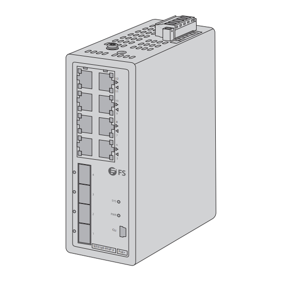
Hardware-Übersicht Ports an der Vorderseite RJ45 IES3100-8T4F-P PoE+ Port Beschreibung RJ45 10/100/1000BASE-T-Ports für Ethernet-Verbindung SFP-Port für 1G-Verbindung Ein RJ45 Console-Port für die serielle Verwaltung LEDs an der Vorderseite RJ45 IES3100-8T4F-P PoE+...
Status Beschreibung Der Netzeingang wird mit Strom versorgt. Der Netzeingang wird nicht mit Strom versorgt. Blinkt Das System ist betriebsbereit. Keine Versorgungsspannung oder das System ist nicht betriebsbereit. Ein PoE-Endgerät ist angeschlossen und wird über PoE mit Strom versorgt. Gelb: PoE Es ist kein PoE-Port verfügbar oder die Power-over-Ethernet-Funktion ist deaktiviert.
Rückseite DIN-Schienen-Montageclip Installationsvoraussetzungen Bevor Sie mit der Installation beginnen, vergewissern Sie sich, dass Sie über die folgenden Voraussetzungen verfügen: Workstations mit Windows XP/2003/2008/Vista/7/8/10, MAC OS X oder höher, Linux, UNIX oder anderen Plattformen, die mit TCP/IP-Protokollen kompatibel sind. Die Workstations sind mit einer Ethernet NIC (Network Interface Card) ausgestattet. Serieller Port-Anschluss (Terminal) Die oben genannten Workstations sind mit einem COM-Port (DB9) oder einem USB-RS232-Konverter ausgestattet.
Montage des Switches DIN-Schienen-Montage Montage der Einheit Lösen der Einheit 1. Greifen Sie den oberen Teil des Befestigungsclips der DIN-Schiene an der Kante der DIN-Schiene. 2. Drücken Sie die Unterseite des Clips auf die andere Seite der DIN-Schiene. 3. Drücken Sie die Unterseite des Clips nach außen, um ihn leicht zu entfernen. Erdung des Switches 48-57V PWR1...
Connecting the RJ45 Ports ACHTUNG: Der Erdungsanschluss darf erst dann entfernt werden, wenn alle Versorgungsanschlüsse getrennt wurden. Anschließen der RJ45-Ports CL I IE S3 10 0- 8T 4F Po E+ 1. Schließen Sie ein Ethernet-Kabel an den RJ45-Port einer Kamera, eines Outdoor-AP, eines Computers oder eines anderen Netzwerkgeräts an.
Anschließen des Console-Ports (CLI) CL I IE S3 10 0- 8T 4F Po E+ 1. Stecken Sie den RJ45-Stecker in den RJ45-Console-Port an der Vorderseite des Switches. 2. Verbinden Sie die DB9-Buchse des Console-Kabels mit dem seriellen Port des Computers. Anschließen der Stromversorgung Auf der Oberseite des Switches befindet sich eine DC-Eingangsbuchse, die aus einer Klemmleiste mit 5 Kontakten besteht.
Name Beschreibung Positiv Negativ Erfordert eine gute Verbindung Einzelner DC-Eingang (48-57VDC) 1. Stecken Sie die positiven/negativen DC-Stromversorgungsdrähte in die Kontakte 1 und 2 für PWR1. 2. Ziehen Sie die Schrauben der Drahtklemmen fest, damit sich die Drähte nicht lockern können. PWR1 PWR2 Redundanter DC-Doppeleingang (48-57VDC)
Positiv (+) Pin Negativ (-) Pin Pin 1 / 5 Pin 2 / 4 HINWEIS: Der Drahtquerschnitt für die Klemmleiste sollte im Bereich von 12 bis 16 AWG liegen. Konfigurieren des Switches Konfigurieren des Switches über den Console-Port Schritt 1: Schließen Sie einen Computer über das Console-Kabel an den Console-Port des Switches an. Schritt 2: Starten Sie die Terminalsimulationssoftware, z.
Konfigurieren des Switches mit der webbasierten Schnittstelle Schritt 1: Schließen Sie einen Computer über das Netzwerkkabel an den Management-Port des Switches an. Schritt 2: Stellen Sie die IP-Adresse des Computers auf 192.168.1.x ein (""x"" ist eine beliebige Zahl zwischen 2 und 254). I nter net Pro toco l Ver s i on 4 ( TCP / I P v 4) Prop er ties General Yo u c a n g e t I P s e t t i n g s a s s i g n e d a u t o m a t i c a l l y i f y o u r n e t w o r k...
Fehlersuche Der 100M/1G-Port funktioniert nicht 1. Vergewissern Sie sich, dass das optische Modul und das Kabel keine Probleme aufweisen. 2. Prüfen Sie, ob die Konfiguration an beiden Enden des Kommunikationsgeräts auf automatische oder erzwungene Rate eingestellt ist. Fehlgeschlagene Fernverbindung des Switches 1.
Kontakt https://www.fs.com/de/contact_us.html Produktgarantie FS garantiert seinen Kunden, dass wir bei Schäden oder fehlerhaften Artikeln, die auf unsere Verarbeitung zurückzuführen sind, eine kostenlose Rückgabe innerhalb von 30 Tagen nach Erhalt der Ware anbieten. Dies gilt nicht für Sonderanfertigungen oder maßgeschneiderte Lösungen.
Introduction Nous vous remercions d'avoir choisi le Switch Industriel Manageable L2+ IES3100-8T4F-P. Ce guide est conçu pour vous familiariser avec la configuration du switch et décrit comment procéder à son déploiement. IES3100-8T4F-P PoE+ IES3100-8T4F-P Accessories Câble Console x1 NOTE :...
Aperçu du Matériel Ports du Panneau Frontal RJ45 IES3100-8T4F-P PoE+ Ports Description RJ45 Ports 10/100/1000BASE-T pour la connexion Ethernet Ports SFP pour une connexion 1G Un port console RJ45 pour la gestion en série Indicateurs LED du Panneau Frontal RJ45...
Statut Description Allumé L'alimentation est fournie. Éteint L'alimentation n'est pas fournie. Clignote Le système est opérationnel. Absence de tension d'alimentation ou le système Éteint n'est pas opérationnel. Un dispositif terminal PoE est connecté et Allumé reçoit une alimentation via PoE. Jaune : PoE Aucun port PoE n'est disponible ou la fonction Éteint...
Panneau Arrière Clip de Montage pour Rail DIN Exigences d'Installation Avant l'installation, assurez-vous que vous disposez des éléments suivants : Postes de travail équipés de Windows XP/2003/2008/Vista/7/8/10, MAC OS X ou version ultérieure, Linux, UNIX, ou autres plateformes compatibles avec les protocoles TCP/IP. Les postes de travail sont munis d'une carte d'Interface Réseau (NIC) Ethernet.
Seite 30
Installation du Switch Installation sur Rail DIN Montage de l'unité Libération de l'unité 1. Saisissez la partie supérieure du clip de montage du rail DIN. 2. Pressez le bas du clip sur l'autre côté du rail DIN. 3. Poussez le bas du clip vers l'extérieur pour le retirer facilement. Mise à...
Seite 31
ATTENTION : La connexion de terre ne doit pas être retirée avant que toutes les connexions d'alimentation ne soient déconnectées. Connexion des Ports RJ45 CL I IE S3 10 0- 8T 4F Po E+ 1. Connectez un câble Ethernet au port RJ45 de caméras IP, téléphones IP, points d'accès (AP) ou tout autre périphérique réseau.
2. Branchez l'émetteur-récepteur SFP compatible au port SFP. 3. Connectez un câble à fibre optique à l'émetteur-récepteur à fibre. Puis connectez l'autre extrémité du câble à un autre dispositif à fibre. Connexion du Port Console CL I IE S3 10 0- 8T 4F Po E+ 1.
Seite 33
N° Nomination Description Positif Négatif Bonne connexion requise Entrée DC Unique (48-57VDC) 1. Insérez les fils d'alimentation DC positifs/négatifs dans les contacts 1 et 2 du PWR1. 2. Serrez les vis de serrage des fils pour éviter qu'ils ne se relâchent. PWR1 PWR2 Double Entrée DC Redondante (48-57VDC)
Seite 34
Broche Positive (+) Broche Négative (-) Pin 1 / 5 Pin 2 / 4 NOTE : Le calibre du fil pour le bornier doit être entre 12 et 16AWG. Configuration du Switch Configuration du Switch à l'Aide du Port Console Étape 1 : Connectez un ordinateur au port de console du switch à...
Seite 35
Configuration du Switch à l'Aide de l'Interface Web Étape 1 : Connectez un ordinateur à n'importe quel port Ethernet du switch à l'aide du câble réseau. Étape 2 : Définissez l'adresse IP de l'ordinateur sur 192.168.1.x ("x" est un nombre compris entre 2 et 254).
Seite 36
Dépannage Le Port 100M/1G ne Fonctionne pas 1. Assurez-vous que le module optique et le câble ne présentent aucun problème. 2. Vérifiez si la configuration aux deux extrémités du dispositif de communication est le débit automatique ou forcé. Connexion à Distance du Switch Echouée 1.
Garantie du Produit FS garantit à ses clients que tout article endommagé ou défectueux dû à sa fabrication pourra être retourné gratuitement dans un délai de 30 jours à compter de la date de réception de la marchandise. Ceci exclut les articles faits sur mesure ou les solutions personnalisées.
Die FS.COM GmbH erklärt hiermit, dass dieses Gerät mit der Richtlinie 2014/30/EU und 2014/35/EU . Eine Kopie der EU-Konformitätserklärung finden Sie unter www.fs.com/de/company/quality_control.html. FS.COM GmbH déclare par la présente que cet appareil est conforme à la Directive 2014/30/UE et 2014/35/UE. Une copie de la Déclaration UE de Conformité est disponible sur https://www.fs.com/fr/company/quality_control.html FS.COM LIMITED...
Seite 39
CAN ICES-003(A)/NMB-003(A) English: This device contains licence-exempt transmitter(s)/receiver(s) that comply with Innovation, Science and Economic Development Canada’s licence-exempt RSS(s). Operation is subject to the following two conditions: (1) This device may not cause interference. (2) This device must accept any interference, including interference that may cause undesired operation of the device.