Herunterladen Inhalt Inhalt Diese Seite drucken
FS IES3110-8TF Schnellstartanleitung

FS IES3110-8TF Schnellstartanleitung

L2+ managed industrieller switch
Vorschau ausblenden Andere Handbücher für IES3110-8TF:

Werbung

Verfügbare Sprachen

Verfügbare Sprachen

IES3110-8TF Switch
L2+ MANAGED INDUSTRIAL SWITCH
L2+ MANAGED INDUSTRIELLER SWITCH
SWITCH INDUSTRIEL MANAGEABLE L2+
Quick Start Guide
Quick-Start Anleitung
Guide de Démarrage Rapide
P 1
P 2
F A U L T
R IN G
R .O .
9
1 0
L in k
1 G /2 .5 G
Li n k/ A ct
A c t
1 G /2 .5 G
Li n k/ A ct
9
1 0
S F P
R E S E T
L in k
A c t
1 0 0 0
7
8
5
6
3
4
1
2
IE S 3 1 1 0 -
8 T F
V1.0

Werbung

Inhaltsverzeichnis
loading

Inhaltszusammenfassung für FS IES3110-8TF

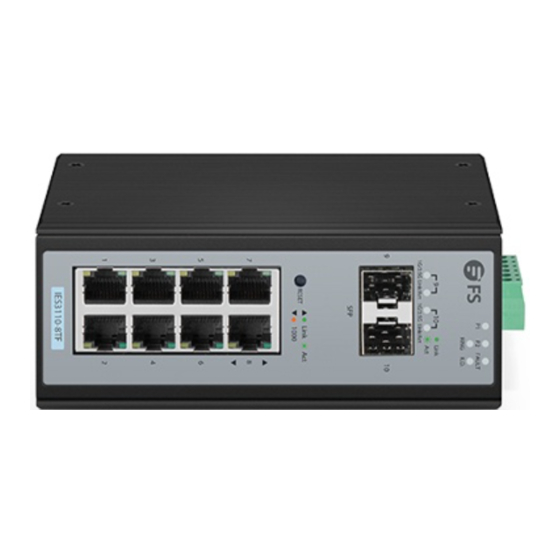
  • Seite 1 R E S E T L in k A c t 1 0 0 0 IE S 3 1 1 0 - 8 T F IES3110-8TF Switch L2+ MANAGED INDUSTRIAL SWITCH L2+ MANAGED INDUSTRIELLER SWITCH SWITCH INDUSTRIEL MANAGEABLE L2+ Quick Start Guide V1.0 Quick-Start Anleitung Guide de Démarrage Rapide...
  • Seite 2 Introduction Thank you for choosing IES3110-8TF Managed Switch. This guide is designed to familiarize you with the layout of the switch and describes how to deploy the switch in your network. FAULT RING R.O. Link 1G/2.5G Link/Act 1G/2.5G Link/Act Link...
  • Seite 3: Hardware Overview

    R.O. Link 1G/2.5G Link/Act 1G/2.5G Link/Act 2x 100/1000/2500BASE-X SFP Ports Link RESET 1000 8x 10/100/1000BASE-T Ports IES3110-8TF Ports Description RJ45 10/100/1000BASE-T ports for Ethernet connection SFP ports for 100M/1G/2.5G connection Upper Panel Grounding Point Max. fault loading: 24V,1A 2 3 4 5 6...
  • Seite 4: Rear Panel

    Rear Panel DIN-rail Mounting Kit Front Panel LEDs FAULT RING R.O. Link 1G/2.5G Link/Act 1G/2.5G Link/Act Link RESET 1000 RJ45 IES3110-8TF...
  • Seite 5: Installation Requirements

    LEDs Status Description Green Indicates the Switch has power. Green Indicates the Switch has power. SYSTEM Fault Green Indicates power failure. Ring Green Indicates that the ERPS Ring has been created successfully. R.O. Indicates that Switch has been enabled to Ring Owner. Green Indicates the link through that port is successfully Light...
  • Seite 6: Mounting The Switch

    Mounting the Switch DIN-Rail Mounting Mounting the unit Releasing the unit 1. Position the unit in front of the DIN-Rail and hook the mount bracket over the top of the rail. 2. Rotate the switch downward towards the rail to lock it into place. You will know it is secure when you hear the click.
  • Seite 7 Grounding the Switch Grounding and wire routing help limit the effects of noise due to electromagnetic interference (EMI). Run the ground connection from the ground screw to the grounding surface prior to connecting devices. Max. fault loading: 24V,1A 2 3 4 5 6 V1+ V1 V2+ V2 DC Input: 12-48V,1.25A max.
  • Seite 8 Name Description V1+, V2+ Live line/Positive V1-, V2- Null line/Negative Requiring good ground connection 2. Tighten the wire-clamp screws for preventing the wires from loosening. PWR1 PWR2 Positive (+) Pin Negative (-) Pin Pin 1 / 5 Pin 2 / 6 NOTE: The wire gauge for the terminal block should be in the range from 12 to 24 AWG.
  • Seite 9 Connecting the RJ45 Ports FA UL T RIN G R.O . Lin k 1G /2. 5G Lin k/A ct Ac t 1G /2. 5G Lin k/A ct SF P RE SE T Li nk Ac t 10 00 IE S 3 1 1 0 -8 1.
  • Seite 10: Troubleshooting

    Configuring the Switch Configuring the Switch Using the Web-based Interface Step 1: Connect the computer to any RJ45 port of the switch using the network cable. Step 2: Set the IP address of the computer to 192.168.1.x ("x" is any number from 2 to 255). Step 3: Open a web browser, enter the default IP address of the switch 192.168.1.1, and enter the default username and password, admin/admin.
  • Seite 11: Support And Other Resources

    Product Warranty FS ensures our customers that any damage or faulty items due to our workmanship, we will offer a free return within 30 days from the day you receive your goods. This excludes any custom made items or tailored solutions.
  • Seite 12 FAULT RING R.O. Link 1G/2.5G Link/Act 1G/2.5G Link/Act Link RESET 1000 IES3110-8TF IES3110-8TF Zubehör Montagehalterung x2 M3-Schraube x4 Hinweis: Beim Switch IES3100-8TF werden Staubschutzkappen mitgeliefert. Bewahren Sie die Staubschutzkappen ordnungsgemäß auf, und verwenden Sie sie zum Schutz ungenutzter optischer Ports.
  • Seite 13: Hardware-Übersicht

    RING R.O. Link 1G/2.5G Link/Act 1G/2.5G Link/Act 2x 100/1000/2500BASE-X SFP-Ports Link RESET 1000 8x 10/100/1000BASE-T- Ports IES3110-8TF Ports Beschreibung RJ45 10/100/1000BASE-T Ports für Ethernet-Verbindung SFP-Ports für 100M/1G/2,5G-Verbindung Obere Platte Erdungspunkt Max. fault loading: 24V,1A 2 3 4 5 6 V1+ V1 V2+ V2 DC Input: 12-48V,1.25A max.
  • Seite 14: Leds An Der Vorderseite

    Rückplatte Montagekit für DIN-Hutschiene LEDs an der Vorderseite FAULT RING R.O. Link 1G/2.5G Link/Act 1G/2.5G Link/Act Link RESET 1000 RJ45 IES3110-8TF...
  • Seite 15: Status Beschreibung

    LEDs Status Beschreibung Grün Switch wird mit Strom versorgt. Grün Switch wird mit Strom versorgt. SYSTEM Fehler Grün Switch wird nicht mit Strom versorgt. Grün Ring Der EPS-Ring wird erfolgreich erstellt. R.O. Grün Switch wird für den Ring Besitzer aktiviert. Die Verknüpfungen zu den Port werden erfolgreich etabliert.
  • Seite 16: Montage Des Switches

    Montage des Switches Montage für DIN-Hutschiene Gerät montieren Gerät entfernen 1. Positionieren Sie das Gerät vor der DIN-Hutschiene und haken Sie die Montagehalterung über der Oberseite der Hutschiene ein. 2. Drehen Sie den Switch nach unten in Richtung der Hutschiene, um ihn zu verriegeln. Wenn Sie ein Klicken hören, ist der Switch fest in der Hutschiene.
  • Seite 17: Erdung Des Switches

    Erdung des Switches Erdung und Kabelführung tragen dazu bei, die Auswirkungen von Rauschen aufgrund elektromagnetischer Störungen (EMI) zu begrenzen. Führen Sie die Erdungsverbindung von der Erdungsschraube zur Erdungsfläche, bevor Sie Geräte anschließen. Max. fault loading: 24V,1A 2 3 4 5 6 V1+ V1 V2+ V2 DC Input: 12-48V,1.25A max.
  • Seite 18 Name Beschreibung V1+, V2+ Live Line/Positiv V1-, V2- Null Line/Negativ Erfordert eine gute Masseanschluss 2. Ziehen Sie die Drahtklemmschrauben fest, um ein Lösen der Drähte zu verhindern. PWR1 PWR2 Positive (+) Pin Negative (-) Pin Pin 1 / 5 Pin 2 / 6 HINWEIS: Die Drahtstärke für die Klemmleiste sollte im Bereich von 12 bis 24 AWG liegen.
  • Seite 19: Anschließen Der Rj45-Ports

    Anschließen der RJ45-Ports FA UL T RIN G R.O . Lin k 1G /2. 5G Lin k/A ct Ac t 1G /2. 5G Lin k/A ct SF P RE SE T Li nk Ac t 10 00 IE S 3 1 1 0 -8 1.
  • Seite 20: Fehlerbehebung

    Konfigurieren des Switsches Konfigurieren des Switches über die webbasierte Schnittstelle Schritt 1: Schließen Sie den Computer über das Netzwerkkabel an den beliebigen RJ45-Port des Switches an. Schritt 2: Stellen Sie die IP-Adresse des Computers auf 192.168.2.x ein ("x" ist eine beliebige Zahl zwischen 2 und 255).
  • Seite 21: Support Und Andere Ressourcen

    Produktgarantie FS garantiert den Kunden, dass wir bei Schäden oder fehlerhaften Artikeln, die auf unsere Verarbeitung zurückzuführen sind, eine kostenlose Rückgabe innerhalb von 30 Tagen nach Erhalt der Ware anbieten. Dies gilt nicht für maßgefertigte Artikel oder maßgeschneiderte Lösungen.
  • Seite 22 Introduction Merci d'avoir choisi le Switch Manageable IES3110-8TF. Ce guide est conçu pour que vous puissiez vous familiariser avec la configuration du switch et vous indiquer comment procéder à son déploiement. FAULT RING R.O. Link 1G/2.5G Link/Act 1G/2.5G Link/Act Link...
  • Seite 23: Aperçu Du Matériel

    Link 1G/2.5G Link/Act 1G/2.5G Link/Act 2 Ports SFP 100/1000/2500BASE-X Link RESET 1000 8 Ports 10/100/1000BASE-T IES3110-8TF Ports Description RJ45 Ports 10/100/1000BASE-T pour connexion Ethernet Ports SFP pour connexion 100M/1G/2.5G Panneau Supérieur Borne du Point de Mise à la Terre Max. fault loading: 24V,1A...
  • Seite 24: Panneau Arrière

    Panneau Arrière Kit de Montage de Rail DIN Indicateurs LED du Panneau Frontal FAULT RING R.O. Link 1G/2.5G Link/Act 1G/2.5G Link/Act Link RESET 1000 RJ45 IES3110-8TF...
  • Seite 25: Exigences D'installation

    Indicateur LED Statut Description Vert Indique que le Switch est sous tension. Vert Indique que le Switch est sous tension. SYSTEM Fault Vert Indique une panne de courant. Vert Ring Indique que l'Anneau ERPS a été créé avec succès. Indique que le Switch a été activé pour le Propriétaire de R.O.
  • Seite 26: Montage Mural

    Montage du Switch Montage sur Rails DIN Montage de l'unité Retrait de l'unité 1. Positionnez l'unité en face du rail DIN et accrochez le support de montage sur le haut du rail. 2. Orientez le switch en direction du rail pour le verrouiller en place. Vous saurez qu'il est bien fixé lorsque vous entendrez un clic.
  • Seite 27: Connexion De L'alimentation

    Mise à la Terre du Switch La mise à la terre et le routage des fils permettent de limiter les effets du bruit dû aux interférences électromagnétiques (EMI). Faites passer la connexion de terre à la surface de mise à la terre avant de connecter les appareils.
  • Seite 28 Désignation Description V1+, V2+ Ligne directe/Positif V1-, V2- Ligne nulle/Négatif Requiert une bonne connexion à la terre 2. Serrez les vis de serrage des fils pour éviter qu'ils ne se desserrent. PWR1 PWR2 Broche Positive (+) Broche Négative (-) Broches 1/5 Broches 2/6 NOTE: Le calibre des fils du bornier doit être entre 12 et 24AWG.
  • Seite 29 Connexion des Ports RJ45 FA UL T RIN G R.O . Lin k 1G /2. 5G Lin k/A ct Ac t 1G /2. 5G Lin k/A ct SF P RE SE T Li nk Ac t 10 00 IE S 3 1 1 0 -8 1.
  • Seite 30: Dépannage

    Configuration du Switch Configuration du Switch à l'Aide de l'Interface Web Étape 1 : Connectez l'ordinateur à n'importe quel port RJ45 du switch à l'aide du câble réseau. Étape 2 : Définissez l'adresse IP de l'ordinateur sur 192.168.1.x ("x" est un nombre quelconque compris entre 2 et 255).
  • Seite 31: Garantie Du Produit

    Garantie du Produit FS garantit à ses clients que tout article endommagé ou défectueux dû à sa fabrication pourra être retourné gratuitement dans un délai de 30 Jours à compter de la date de réception de la marchandise. Ceci exclut les articles faits sur mesure ou les solutions personnalisées.
  • Seite 32: Compliance Information

    Any changes or modifications not expressly approved by the grantee of this device could void the user's authority to operate the equipment. Responsible party (only for FCC matter) FS.COM Inc. 380 Centerpoint Blvd, New Castle, DE 19720, United States https://www.fs.com...
  • Seite 33 FS.COM GmbH hereby declares that this device is in compliance with the Directive 2014/30/EU. A copy of the EU Declaration of Conformity is available at www.fs.com/company/quality_control.html Die FS.COM GmbH erklärt hiermit, dass dieses Gerät mit der Richtlinie 2014/30/EU konform ist. Eine Kopie der EU-Konformitätserklärung finden Sie unter...

Inhaltsverzeichnis