Mettler Toledo InPro 5000 Bedienungsanleitung
Co2 sensor
Vorschau ausblenden
Andere Handbücher für InPro 5000:
- Bedienungsanleitung (76 Seiten) ,
- Bedienungsanleitung (56 Seiten) ,
- Bedienungsanleitung (56 Seiten)
Inhaltsverzeichnis

Verwandte Anleitungen für Mettler Toledo InPro 5000


Inhaltszusammenfassung für Mettler Toledo InPro 5000
- Seite 1 52002465_F_IM_InPro5000i_edf_2022_09.qxp_52002465_F_IM_InPro5000_edf_2022 InPro 5000 (i) CO Sensors Instruction manual Bedienungsanleitung Instructions d’utilisation InPro 5000 (i) 52 002 465 F...
- Seite 2 52002465_F_IM_InPro5000i_edf_2022_09.qxp_52002465_F_IM_InPro5000_edf_2022 InPro 5000 (i) CO Sensor 12 mm English Page Deutsch Seite 21 Français Page InPro 5000 (i) © 09 / 2022 METTLER TOLEDO 52 002 465 F Printed in Switzerland...
- Seite 3 52002465_F_IM_InPro5000i_edf_2022_09.qxp_52002465_F_IM_InPro5000_edf_2022 InPro 5000 (i) CO Sensor 12 mm InPro 5000 (i) CO Sensors Instruction manual © 09 / 2022 METTLER TOLEDO InPro 5000 (i) Printed in Switzerland 52 002 465 F...
-
Seite 4: Inhaltsverzeichnis
Scope of delivery ..........8 Equipment features ..........9 Preparation............10 Start-up ............10 Calibration............11 4.2.1 Connecting the InPro 5000 (i) to cable....11 4.2.2 Connecting the VP cable to the transmitter ....12 4.2.3 Calibation of pH electrode........12 Mounting the membrane body ......13 Mounting the sensor ..........14 Sterilization............14... -
Seite 5: Introduction
Introduction Thank you for buying the InPro™ 5000 (i) sensor from METTLER TOLEDO. The construction of the InPro 5000 (i) sensor employs leading edge technology and complies with safety regulations currently in force. Notwithstanding this, improper use could lead to hazards for the user or a third-party, and / or adverse effects on the plant or other equipment. -
Seite 6: Important Notes
Intended use InPro 5000 (i) sensors are intended solely for in line measurement of dissolved CO (carbon diox- ide), as described in this instruction manual. -
Seite 7: Safety Instructions
52002465_F_IM_InPro5000i_edf_2022_09.qxp_52002465_F_IM_InPro5000_edf_2022 InPro 5000 (i) CO Sensor 12 mm Safety instructions – The InPro 5000 (i) sensors should be installed, operated, maintained only by personnel familiar with the sensor and who are qualified for such work. – A defective sensor must neither be install ed nor put into service. -
Seite 8: Product Description
InPro 5000 (i) CO Sensor 12 mm Product description General information The sensor InPro 5000 (i) with integrated temperature probe is used for dissolved carbon dioxide meas ure - ment. The sensor has been designed for accurate and precise measurement at low to medium carbon dioxide partial pressure. -
Seite 9: Equipment Features
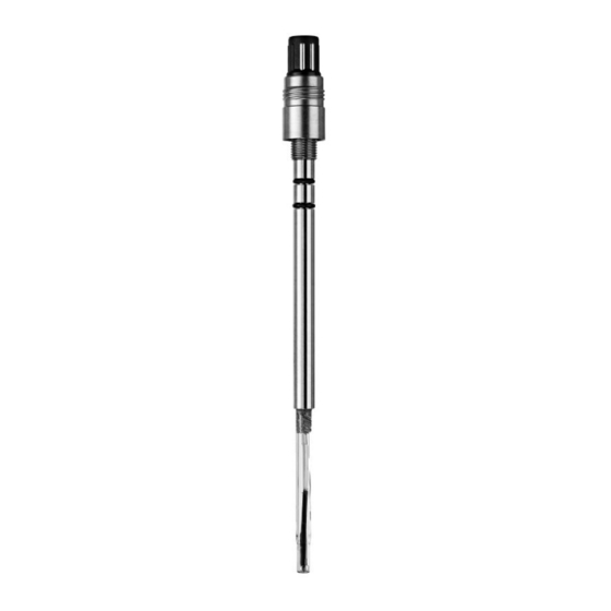
Pg 13.5 threaded sleeve Washer PTFE O-ring (10.77 x 2.62 mm, silicone FDA) Retainer nut Cap sleeve Membrane body Interior body (pH electrode) Wetting cap © 09 / 2022 METTLER TOLEDO InPro 5000 (i) Printed in Switzerland 52 002 465 F... -
Seite 10: Preparation
The interior body (pH electrode) is ready for cali- bration. – On unpacking, check the pH electrode for mechanical damage. Report any damage imme- diately to your METTLER TOLEDO supplier. – Remove the watering cap, cap sleeve, membrane body and briefly rinse the sensor with de-ionized water. -
Seite 11: Calibration
InPro 5000 (i) CO Sensor 12 mm Calibration Purpose of calibration: Each CO sensor and Interior body (pH electrode) has its individual slope and zero point. 4.2.1 Connecting the InPro 5000 (i) to cable VP cable AK9 cable Plug Plug Notch Notch... -
Seite 12: Connecting The Vp Cable To The Transmitter
Important settings : On the transmitter, select Pt1000 as temperature sensor for the analog InPro 5000. ISM digital InPro 5000 i does not require a temperature set- ting. Important: Please do not leave the sensor in the calibra- tion buffer for longer than 1 hour. -
Seite 13: Mounting The Membrane Body
– Carefully slip the cap sleeve over the fitted membrane body, holding the sensor in a vertical position and screw it tight. The cap sleeve must be clean and tight. © 09 / 2022 METTLER TOLEDO InPro 5000 (i) Printed in Switzerland 52 002 465 F... -
Seite 14: Mounting The Sensor
(InFit761-... or InTrac797) for correct sensor installation. The InPro 5000 (i) sensor can be mounted directly on a top plate of a small bioreactor or in a pipe with an inside Pg 13.5 thread and securely tightened via the Pg 13.5 threaded sleeve. -
Seite 15: Operation
Sensor 12 mm Operation Calibration of the CO sensor The InPro 5000 (i) sensor can be calibrated with CO gas or a CO gas mixture. Example: If a CO partial pressure of 150 mbar is expected, you can use a gas with 15 % CO... -
Seite 16: Maintenance
(see section 4.3). After each calibration of the pH electrode (section 4.2) new CO electrolyte should be filled in the membrane body. InPro 5000 (i) © 09 / 2022 METTLER TOLEDO 52 002 465 F Printed in Switzerland... -
Seite 17: Maintenance Of The Interior Body
Asset Suite software. The calibration history gives valuable information re- garding the quality of the calibration and the ageing of the interior body. © 09 / 2022 METTLER TOLEDO InPro 5000 (i) Printed in Switzerland 52 002 465 F... -
Seite 18: Storage
Detection limit 10 hPa CO Response time 90 % of final value < 120 sec (at 25 °C [77 °F] from air to CO InPro 5000 (i) © 09 / 2022 METTLER TOLEDO 52 002 465 F Printed in Switzerland... -
Seite 19: Ordering Information
52002465_F_IM_InPro5000i_edf_2022_09.qxp_52002465_F_IM_InPro5000_edf_2022 InPro 5000 (i) CO Sensor 12 mm Ordering information Sensors Designation: InPro 5000 (i) / 12 / a (a = immersion length in mm) Designation Order No. InPro5000 i/12/120 30 013 606 InPro5000 i/12/220 30 019 005 InPro5000 i/12/320... -
Seite 20: Transmitter
52 121 350 M700 CO 5700 i (analog only) 52 121 267 M800 Process 2-Ch 52 121 813 M800 Process 4-Ch 52 121 853 InPro 5000 (i) © 09 / 2022 METTLER TOLEDO 52 002 465 F Printed in Switzerland... - Seite 21 52002465_F_IM_InPro5000i_edf_2022_09.qxp_52002465_F_IM_InPro5000_edf_2022 InPro 5000 (i) CO Sensor 12 mm InPro 5000 (i) CO -Sensoren Bedienungsanleitung © 09 / 2022 METTLER TOLEDO InPro 5000 (i) Printed in Switzerland 52 002 465 F...
- Seite 22 -Messung ........26 Lieferumfang.............26 Produktübersicht ..........27 Inbetriebnahme..........28 Start-up ............28 Kalibrierung ............29 4.2.1 InPro 5000 (i) Sensor an ein Kabel anschliessen..29 4.2.2 Anschluss des VP-Kabels an den Transmitter..30 4.2.3 Kalibrierung des Innenkörpers (pH-Elektrode) ..30 Membrankörper montieren........31 Installation des Sensors ........32 Sterilisierung .............32 Betrieb ............33...
-
Seite 23: Einleitung
Wir danken Ihnen, dass Sie einen CO -Sensor InPro™ 5000 (i) von METTLER TOLEDO erworben ha- ben. Die Sensoren InPro 5000 (i) sind nach dem heutigen Stand der Technik und den zur Zeit anerkannten sicherheitstechnischen Regeln gebaut. Dennoch kön- nen bei unsachgemässer Anwendung Gefahren für den Anwender oder Dritte und / oder Beeinträchtigungen der... -
Seite 24: Wichtige Hinweise
Sensor 12 mm Wichtige Hinweise Hinweise zur Bedienungsanleitung Die vorliegende Bedienungsanleitung enthält alle An- gaben, um den Sensor InPro 5000 (i) sicher, sachge- recht und bestimmungsgemäss einzusetzen. Die Bedienungsanleitung richtet sich an das mit der Bedienung und der Instandhaltung der Sensoren betraute Personal. -
Seite 25: Sicherheitshinweise
– Der Betrieb unter Beachtung der vorgeschriebenen Umwelt und Betriebsbedingungen und den zuläs- sigen Einbaulagen. Sicherheitshinweise – Die Sensoren InPro 5000 (i) dürfen nur von Perso- nen installiert, bedient und gewartet werden, die mit diesen Produkten vertraut und für solche Arbeit qualifiziert sind. -
Seite 26: Produktbeschreibung
Imbus-Schraube am Sensorschaft gesi- chert wird. Prinzip der CO -Messung Der Sensor InPro 5000 (i) arbeitet nach einem poten- tiometrischen Prinzip (Severinghaus) und ist mit einer gasdurchlässigen Membran ausgestattet, welche über eine pH-Elektrode mit einer flachen Glasmembran ge- spannt ist. -
Seite 27: Produktübersicht
InPro 5000 i ISM-Steckkopf Imbus-Schraube Pg 13.5 Gewindehülse Gleitscheibe PTFE O-Ring (10.77 x 2.62 mm, Silikon FDA) Kontermutter Überwurfhülse Membrankörper Innenkörper (pH Elektrode) Wässerungskappe © 09 / 2022 METTLER TOLEDO InPro 5000 (i) Printed in Switzerland 52 002 465 F... -
Seite 28: Inbetriebnahme
äusseren Stahlschaft montiert ist. Der VP- Steckkopf darf sich nicht drehen lassen. Sonst muss die kleine Imbus-Schraube unterhalb des Steckkopfs stärker angezogen werden. InPro 5000 (i) © 09 / 2022 METTLER TOLEDO 52 002 465 F Printed in Switzerland... -
Seite 29: Kalibrierung
InPro 5000 (i) CO Sensor 12 mm Kalibrierung Zweck der Kalibrierung: Jeder CO -Sensor und jeder Innenkörper (pH-Elektrode) besitzt eine individuelle Steigung und Nullpunkt. 4.2.1 InPro 5000 (i) Sensor an ein Kabel anschliessen VP-Kabel AK9-Kabel Kabelbuchse Kabelbuchse VP-Steckkopf ISM-Steckkopf InPro 5000 InPro 5000 i Der Sensor wird über ein VP- oder AK9-Kabel an den... -
Seite 30: Anschluss Des Vp-Kabels An Den Transmitter
Wichtige Einstellung: Transmitter auf Pt 1000 Tem- peraturfühler konfigurieren für den analogen InPro 5000. Der digitale ISM Sensor InPro 5000 i benötigt keine Temperatureinstellung. Wichtig: Den Sensor keinesfalls länger als 1 Stunde im Kalibrierpuffer lassen. Zu lange Verweildauer kann dazu führen, dass der Sensor im Prozess stark driftet. -
Seite 31: Membrankörper Montieren
– Überwurfhülse sorgfältig über den Membrankörper schieben, währenddem der Sensor senkrecht ge- halten wird. Überwurfhülse handfest anschrauben. Die Überwurfhülse muss sauber und dicht sein. © 09 / 2022 METTLER TOLEDO InPro 5000 (i) Printed in Switzerland 52 002 465 F... -
Seite 32: Installation Des Sensors
Der Einbau des Sensors in eine Armatur wie InFit 761-... oder InTrac 797 ist in den jeweiligen Anleitungen genau beschrieben. Der InPro 5000 (i) Sensor kann auch direkt in die Deckelplatte eines kleinen Bioreaktors oder in eine Rohrleitung eingebaut werden, sofern ein Pg 13.5 Innengewinde vorhanden ist. -
Seite 33: Betrieb
52002465_F_IM_InPro5000i_edf_2022_09.qxp_52002465_F_IM_InPro5000_edf_2022 InPro 5000 (i) CO Sensor 12 mm Betrieb Kalibrierung des CO -Sensors Der InPro 5000 (i) Sensor kann mit CO -Gas oder mit einer CO -Gasmischung kalibriert werden. Beispiel: Wenn in der Fermentation ein CO -Partial- druck von 150 mbar erwartet wird, kann mit Vorteil ein... -
Seite 34: Wartung
VP-Modul wählen. Zusätzlich ist es möglich, die Linearität, die korrekte Temperaturkompensation und die Qualität der Eingangsstufe (Eingangswiderstand, Eingangsstrom) des CO -Transmitters zu überprüfen. InPro 5000 (i) © 09 / 2022 METTLER TOLEDO 52 002 465 F Printed in Switzerland... -
Seite 35: Auswechseln Des Co
Betriebs steigt die Belastung für den Sensor. Die über die Zeit aufgetretene Sensorbelastung geteilt durch die bereits vergangene Zeit bildet die Basis der Berechnung der noch verbleibenden Nutzungsdauer. © 09 / 2022 METTLER TOLEDO InPro 5000 (i) Printed in Switzerland 52 002 465 F... -
Seite 36: Lagerung
Zertifikat be- zieht. Alle mediumberührten Teile (Sensorschaft, Überwurf- mutter, Membrankörper) sind poliert mit einer Rauhig- keit kleiner 0,4 μm, entsprechend N5 (ISO 1320:1992). InPro 5000 (i) © 09 / 2022 METTLER TOLEDO 52 002 465 F Printed in Switzerland... -
Seite 37: Spezifikationen
10 hPa CO Ansprechzeit < 120 Sek. zum 90 % Endwert (bei 25 °C von Luft zu CO Bestellinformationen Sensor Typenbezeichnung: InPro 5000 (i) / 12 / a (a = Eintauchtiefe in mm) Typenbezeichnung Bestell-Nr. InPro5000 i/12/120 30 013 606 InPro5000 i/12/220... -
Seite 38: Ersatzteile
Überwurfhülse, P-Typ 1.4404 52 200 038 Überwurfhülse, N-Typ 1.4435 52 201 153 Überwurfhülse, P-Typ 1.4435 52 201 154 Innenkörper InPro 5000 i/12/120 Kit 30 019 049 Innenkörper InPro 5000 i/12/220 Kit 30 019 170 Innenkörper InPro 5000 i/12/320 Kit 30 019 175 Innenkörper InPro 5000 i/12/420 Kit... - Seite 39 52002465_F_IM_InPro5000i_edf_2022_09.qxp_52002465_F_IM_InPro5000_edf_2022 InPro 5000 (i) CO Sensor 12 mm Sondes CO InPro 5000 (i) Instructions d’utilisation © 09 / 2022 METTLER TOLEDO InPro 5000 (i) Printed in Switzerland 52 002 465 F...
- Seite 40 Aperçu du produit ..........45 Mise en service..........46 Préparatifs ............46 Etalonnage ............47 4.2.1 Connexion du capteur InPro 5000 au câble VP..47 4.2.2 Connexion du câble VP au transmetteur ....48 4.2.3 Etalonnage du corps interne (électrode de pH)..48 Montage du corps de membrane......49 Installation du capteur........49...
-
Seite 41: Introduction
Nous vous remercions d’avoir acheté un capteur CO InPro™ 5000 (i) de METTLER TOLED0. Les capteurs InPro 5000 (i) sont construits selon l’état actuel de la technique et selon les règles de sécurité technique reconnues. Un emploi inadéquat peut toute- fois mettre en danger l’opérateur ou des tiers, et / ou... -
Seite 42: Remarques Importantes
éventuel arrêt de pro- duction. Utilisation prévue Comme le décrit le présent manuel, les capteurs InPro 5000 (i) sont uniquement destinés à la mesure en ligne du dioxyde de carbone (CO ) dissous. Toute autre utilisation, ou utilisation non mentionnée dans le présent manuel, est considérée comme non... -
Seite 43: Consignes De Sécurité
Consignes de sécurité – L’installation, l’utilisation et la maintenance des capteurs InPro 5000 (i) ne doivent être confiées qu’à des personnes qui connaissent ces produits et qui sont qualifiées pour ce genre de travaux. – Ne pas installer ni mettre en service un capteur défectueux. -
Seite 44: Description Du Produit
à six pans creux. Principe de la mesure du CO Le capteur InPro 5000 (i) fonctionne sur le principe potentiométrique (Severinghaus) et est équipé d’une membrane perméable au gaz tendue par-dessus une électrode de pH à... -
Seite 45: Aperçu Du Produit
PTFE joint torique (10,77 x 2,62 mm, silicone FDA) écrou serré gaine corps de membrane corps interne (électrode de pH) capuchon humidificateur © 09 / 2022 METTLER TOLEDO InPro 5000 (i) Printed in Switzerland 52 002 465 F... -
Seite 46: Mise En Service
Le connecteur VP ne doit pas tourner. Sinon il faut resserrer la petite vis à six pans creux en-dessous du connecteur. InPro 5000 (i) © 09 / 2022 METTLER TOLEDO 52 002 465 F Printed in Switzerland... -
Seite 47: Etalonnage
Sensor 12 mm Etalonnage But de l’étalonnage : chaque capteur CO et chaque corps interne (électrode de pH) a sa pente et son zéro propres. 4.2.1 Connexion du capteur InPro 5000 au câble VP câble VP câble AK9 fiche fiche came... -
Seite 48: Connexion Du Câble Vp Au Transmetteur
9.21. Veuillez observer les instructions de la notice d’emploi du transmetteur. Réglage important : Pour la sonde InPro 5000 confi- gurez le transmetteur sur capteur de température Pt1000. Pour la sonde InPro 5000 i une configuration de la température n’est pas nécessaire. -
Seite 49: Montage Du Corps De Membrane
Le montage du capteur sur un support tel que InFit 761-… ou InTrac 797 est décrit dans les notices correspondantes. Le capteur InPro 5000 (i) peut également être monté directement dans le couvercle d’un petit réacteur biologique ou dans une conduite pourvus d’un taraudage Pg 13,5 dans lequel est vissé... -
Seite 50: Stérilisation
Sensor 12 mm Stérilisation Le capteur installé peut être stérilisé en même temps que le réacteur. Le capteur InPro 5000 peut être stéri- lisé en place ou en autoclave. Pour garantir l’exactitude de mesure il faut, après refroidissement ou avant l’en- semencement, effectuer un étalonnage dans le procédé... -
Seite 51: Maintenance
112 (référence 59 906 431) avec module VP (référence 52 120 939). Ces accessoires permettent de vérifier le câble VP et la connexion correcte au transmetteur. Sélectionnez © 09 / 2022 METTLER TOLEDO InPro 5000 (i) Printed in Switzerland 52 002 465 F... -
Seite 52: Remplacement De L'électrolyte Co /Membrane
Facteurs contribuant à l’usure : • la température pendant la mesure • le nombre de cycles NEP • le nombre de cycles SEP • le nombre d’autoclavages InPro 5000 (i) © 09 / 2022 METTLER TOLEDO 52 002 465 F Printed in Switzerland... -
Seite 53: Conservation
(tige du capteur, écrou raccord, corps de membrane) sont polies avec une rugosité inférieure à 0,4 μm, conformément à N5 (ISO 1320 : 1992). © 09 / 2022 METTLER TOLEDO InPro 5000 (i) Printed in Switzerland 52 002 465 F... -
Seite 54: Spécifications
Câble AK9/20 m 52 300 204 ISM Kit de Vérification 30 031 035 Simulateur de pH 112 pour l’InPro 5000 59 906 431 Module VP pour l’InPro 5000 52 120 939 InPro 5000 (i) © 09 / 2022 METTLER TOLEDO... -
Seite 55: Pièces De Rechange
Douille filetée, modèle N 1.4435 52 201 153 Douille filetée, modèle P 1.4435 52 201 154 Corps interne InPro 5000 i/12/120 Kit 30 019 049 Corps interne InPro 5000 i/12/220 Kit 30 019 170 Corps interne InPro 5000 i/12/320 Kit... - Seite 56 52002465_F_IM_InPro5000i_edf_2022_09.qxp_52002465_F_IM_InPro5000_edf_2022 For addresses of METTLER TOLEDO Market Organizations please go to: www.mt.com/contacts www.mt.com/pro For more information METTLER TOLEDO Group Process Analytics 9001 14001 certified certified Local contact: www.mt.com/contacts Management System certified according to Subject to technical changes ISO 9001 / ISO 14001 ©...