
Verwandte Anleitungen für Balluff BNI CCL-502-100-Z001


Inhaltszusammenfassung für Balluff BNI CCL-502-100-Z001
- Seite 1 BNI CCL-502-100-Z001 CC-Link IO-Link Master Betriebsanleitung deutsch english User’ s guide 中文 用户指南 한국어 사용자 가이드 日本語 ユーザーガイド...
- Seite 2 www.balluff.com...
- Seite 3 BNI CCL-502-100-Z001 CC-Link IO-Link Master Bedienungsanleitung...
-
Seite 4: Inhaltsverzeichnis
5.3. IO-Link Übersicht Eingangs-/Ausgangsdaten ISDU Daten Ereignisse/ Events 5.4. Beispiel für ISDU-Daten 5.5. Beispiel für Ereignisse 5.6. Gateway-Identifikationsdaten Azyklisches Messaging 6.1. Übersicht 6.2. Meldungsstruktur 6.3. Anforderungs-/Antwortdaten Gateway-Identifikation IO-Link Kanaleinstellungen IO-Link-Kanaldaten 6.4. Beschreibung der Anforderungs-/Antwort-Datenpositionen 6.5. Fehlercodes Daten-Mapping 7.1. Profilvoreinstellungen 7.2. Portkonfiguration www.balluff.com... - Seite 5 Balluff Network Interface – CC-Link – BNI CCL-502-100-Z001 7.3. RX und RY 7.4. RX und RY Signaldetails 7.5. RWr und RWw 7.6. RWr und RWw Signaldetails Technische Daten 8.1. Abmessungen 8.2. Mechanische Daten 8.3. Betriebsbedingungen 8.4. Elektrische Daten 8.5. CC-Link Port 8.6.
-
Seite 6: Hinweise
Das Symbol zusammen mit der Aufschrift "Achtung" warnt vor einer möglichen Ge- fahrensituation, die Personen- und Sachschäden hervorrufen kann. Die Nichtbe- achtung dieser Warnhinweise kann zu Personen- oder Sachschäden führen. Beachten Sie unbedingt die beschriebenen Maßnahmen zur Vermeidung dieser Gefahr. www.balluff.com... -
Seite 7: Abkürzungen
Balluff Network Interface CC-Link Hinweise 1.5. Abkürzungen BNI Balluff Netzwerkschnittstelle CC-Link Elektromagnetische Verträglichkeit Funktionserde IO-Link Nicht verfügbar Speicherprogrammierbare Steuerung Hochfrequenz Remote input (Bitdaten) Remote output (Bitdaten) Remote register input (Wort-Daten) Remote register output (Wort-Daten) Standard-Ein-/Ausgang Aktorversorgung Sensorversorgung Bezeichnet einen Eingang... -
Seite 8: Sicherheit
Vor dem Arbeiten an dem Gerät dessen Stromversorgung abschalten. Hinweis Im Interesse einer ständigen Verbesserung des Produkts behält sich die Balluff GmbH vor, die technischen Daten des Produkts und den Inhalt dieser Anlei- tung jederzeit, ohne Ankündigung zu ändern. www.balluff.com... -
Seite 9: Erste Schritte
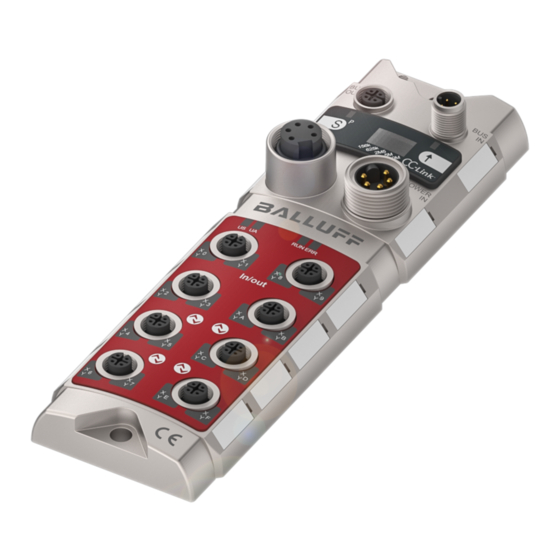
Balluff Network Interface – CC-Link – BNI CCL-502-100-Z001 Erste Schritte 3.1. Modulübersicht 1 Erdanschluss 10 Befestigungsbohrung 2 CC-Link Busausgang 11 CC-Link Buseingang 3 Display 12 Beschriftung 4 Spannungsausgang 13 Spannungsversorgung 5 Status-LEDs 14 Port 4 6 Port 0 15 Pin/Port-LEDs... -
Seite 10: Port
Erste Schritte 3.2. Port Port 0, 1, 4, 5 2, 3, 6, 7 Eingang/Ausgang (PNP) BNI CCL-502-100-Z001 Eingang/Ausgang (PNP) IO-Link 3.3. Mechanischer An- Das Modul wird mittels 2 M6-Schrauben und 2 Unterlegscheiben befestigt. schluss 3.4. Elektrischer Anschluss Spannungsversorgung (7/8”, 5 Pins, Stecker) -
Seite 11: Cc-Link Anschluss
Balluff Network Interface – CC-Link – BNI CCL-502-100-Z001 Erste Schritte 3.5. CC-Link Der CC-Link-Anschluss erfolgt über die M12-Sockel Bus-Ein- und Bus-Ausgänge (A-co- Anschluss diert). CC-Link-Bus-Eingang: (M12, A-codiert, Stecker) Anforderungen Beschreibung Schirm B-Leitung (weiß) Erde (gelb) A-Leitung (blau) CC-Link Bus-Ausgang: (M12, A-codiert, Buchse) -
Seite 12: Display
Display 4.1. Allgemeines Der BNI CCL-502-100-Z001 dient als ausgelagertes E/A- und IO-Link-Gateway-Modul zum Anschluss an ein CC-Link-Netzwerk. Über das eingebaute Display werden die Adresse, die Kommunikationsgeschwindigkeit und die CCL-Modus-Voreinstellungen direkt an den BNI CCL-502-100-Z001-Geräten eingestellt. 4.2. Werkseinstellung Stationsadresse: Kommunikationsgeschwindigkeit: 10 Mbps CC-Link Profil Nr. -
Seite 13: Menüstruktur
Balluff Network Interface – CC-Link – BNI CCL-502-100-Z001 Display 4.4. Menüstruktur Startbildschirm Versionsinfo Start-Zeitüberschreitung (3s) Langer Druckim- Adresse & Baud- Adresse puls auf Rate editieren Änderungen speichern: Kurzer Druckimp- langer Druckimpuls (<3 Sek) auf uls auf Baud-Rate Editieren Druckimpuls editieren auf ... -
Seite 14: Bearbeitungs-Modus
Adresse und Baudrate hin- und herzuschalten. Der BNI CCL-502-100-Z001 dient als ausgelagertes E/A- und IO-Link-Master-Modul zum An- schluss an ein CC-Link-Netzwerk. Über das eingebaute Display werden die Adresse, die Kommunikationsgeschwindigkeit und die CCL-Profil-Voreinstellungen direkt an den BNI CCL- 502-100-Z001-Geräten eingestellt. -
Seite 15: Kommunikations-Schnittstellen Und Modi
Balluff Network Interface – CC-Link – BNI CCL-502-100-Z001 Kommunikations-Schnittstellen und Modi 5.1. CC-Link Das BNI CCL-502-100-Z001 Modul unterstützt sowohl die CC-Link Ver1 als auch die CC-Link Übersicht Ver2 Kommunikation. Ver2 kann größere Datenmengen anhand von mehrfachen Scan-Zyk- len übertragen (erweiterte Zyklen). -
Seite 16: Cc-Link: Zyklische Und Azyklische Kommunikation
5.2. CC-Link: Im Wesentlichen werden Daten zyklisch während der CC-Link Kommunikation übertragen. zyklische und Das BNI CCL-502-100-Z001 Modul verfügt dennoch auch über das azyklische Messaging- Protokoll, das eine Art Kommunikation bei Bedarf darstellt. Dieses wird immer durch den CC- azyklische Link-Master ausgelöst und ermöglicht den Zugang zu spezifischen Funktionsdatenbereichen... -
Seite 17: Io-Link Übersicht
Kommunikations-Schnittstellen und Modi 5.3. IO-Link Übersicht Das Modul BNI CCL-502-100-Z001 verfügt über 4 IO-Link Master-Ports (die so genannten IO-Link Ports*). Wenn ein Port als IOL Port aktiviert ist, werden Pin1, Pin4 und Pin3 für die IO-Link-Kommunikation verwendet, wie im Abschnitt “Verbindungsdaten” beschrieben. Der verbleibende Pin2 ist hierbei ein noch frei konfigurierbarer SIO Pin. -
Seite 18: Beispiel Für Isdu-Daten
Bei Versendung einer ungeraden Anzahl an Bytes wird immer ein Padding-Null-Byte an das Ende des Datenstroms angehängt. Beispiel: Index 0x10 → “BALLUFF”, Länge = 7 Bytes, also wird eine Endung 0x00 angehängt und übermittelt. Dennoch wird immer die tatsächliche (gültige) Datenlänge in der Einheit Byte angegeben. -
Seite 19: Azyklisches Messaging
Balluff Network Interface – CC-Link – BNI CCL-502-100-Z001 Azyklisches Messaging 6.1. Übersicht Das azyklische Messaging wird verwendet, um an die speziellen Daten des Moduls BNI CCL- 502-100-Z001 und der angeschlossenen IO-Link-Geräte zu gelangen. Diese speziellen Funk- tionsdatenbereiche werden anhand von Zugriffsbereichen organisiert. - Seite 20 Byte 6 IO-Link-Kanal 3 Hersteller-ID2 Byte 7 Geräte-ID1 Byte 8 Geräte-ID2 Byte 9 Meldungs- Geräte-ID3 Byte 10 daten Reserviert Byte 11 (fest eingestellt auf 0) Nicht verwendet Seriennummer 1 Byte 12 Seriennummer 16 Byte 27 Nicht verwendet Byte 252 www.balluff.com...
-
Seite 21: Io-Link-Kanaldaten
Balluff Network Interface – CC-Link – BNI CCL-502-100-Z001 Azyklisches Messaging IO-Link Kanal Byte No. Pos. Datenspeicherung Datenspeicher löschen Zugriffs- Byte 0 Code 0x22 0x23 Byte 1 Länge Steue- rung Lesen/Schreiben Nur Schreiben Byte 2 (Status) Port- Reserviert Reserviert Byte 3... -
Seite 22: Beschreibung Der Anforderungs-/Antwort-Datenpositionen
0x02 = Validierung der IO-Link Hersteller-ID, IO-Link Geräte-ID und Seriennummer daten Je nach der Konfiguration der IO-Link Gerätevalidierung wird die Information des an- geschlossenen Geräts geprüft und das Ergebnis durch den Port LED Marker ‘IO- Link’ und ‘IO-Link Kanal hergestellt’ angegeben. www.balluff.com... - Seite 23 Balluff Network Interface – CC-Link – BNI CCL-502-100-Z001 Azyklisches Messaging Pos. Beschreibung Datenspei- cherung Konfiguration der Datenspeicherfunktion des IO-Link-Masters. Das Konfigurations-Byte ist folgendermaßen definiert: – – – – – Datenspeicher Upload (IO-Link Gerät → IO-Link Master) 0: deaktiviert, 1: aktiviert Datenspeicher Download (IO-Link Master →...
-
Seite 24: Fehlercodes
0x84 – Nicht verwendet. Reserve für weitere IOL Fehlercode. 0x9F CCL-502 Fehler im Zusammenhang mit dem Gateway (z.B.: CCL-502 intern Zugriff verweigert) 0xA0 – und/oder und/oder Fehler im Zusammenhang mit dem CC-Link Protokoll (z.B.: 0xFF CC-Link extern Zeitüberschreitung, CRC Fehler) www.balluff.com... - Seite 25 Balluff Network Interface – CC-Link – BNI CCL-502-100-Z001 Azyklisches Messaging Detaillierte Fehlercodeliste (in der Firmware FW3.8) Fehlercode Quelle des Fehlers Beschreibung 0x00 Kein Fehler. Letzter Befehl erfolgreich. 0x11 IOL Gerät ISDU Index nicht verfügbar 0x12 IOL Gerät ISDU Subindex nicht verfügbar 0x20-0x22 IOL Gerät...
- Seite 26 (dieser Fehlercode wird überschrieben, wenn IOL Fehlercodes erzeugt) 0xFF CC-Link, CCL-502 CRC Fehler Bei Fehlercodes mit der Quelle ’IOL Gerät’ siehe: • Dokumentation des IO-Link Geräts, das am CCL-502 Gateway angeschlossen ist • IO-Link standardisierte Fehlercode-Beschreibung, verfügbar über: http://www.io-link.com www.balluff.com...
-
Seite 27: Daten-Mapping
Balluff Network Interface – CC-Link – BNI CCL-502-100-Z001 Daten-Mapping 7.1. Profilvoreinstel- Je nach dem ausgewählten Profil werden die Anzahl an besetzten Stationen, die Version und lungen die erweiterten Zyklus Einstellungen eingestellt. Diese bestimmen die verfügbare Datenmenge für das Gerät und folglich bestimmt ein jeweiliges Profil ebenfalls die Anzahl an Daten pro IO-Link-Kanal. -
Seite 28: Rx Und Ry
RX(m+2)5 RX(m+2)5 Diagnose-Port 5 RY(m+2)5 RY(m+2)5 RX(m+2)6 RX(m+2)6 Diagnose-Port 6 RY(m+2)6 RY(m+2)6 RX(m+2)7 RX(m+2)7 Diagnose-Port 7 RY(m+2)7 RY(m+2)7 RX(m+2)8 US Unterspannung RY(m+2)8 RX(m+2)9 UA Unterspannung RY(m+2)9 Nicht verwendet RX(m+2)A RY(m+2)A RX(m+2)B RY(m+2)B RX(m+2)C RY(m+2)C Nicht verwendet RX(m+2)D RY(m+2)D RX(m+2)E RY(m+2)E RX(m+2)F RY(m+2)F www.balluff.com... - Seite 29 Balluff Network Interface – CC-Link – BNI CCL-502-100-Z001 Daten-Mapping Profil-Nr. Master Slave Profil-Nr. Slave Master P1 – P5 P1 – P5 Signalname Signalname RX(m+2)8 RX(m+3)0 IO-Link Kanal 0 hergestellt RY(m+2)8 RY(m+3)0 IO-Link-Kanal 0 aktivieren RX(m+2)9 RX(m+3)1 IO-Link Kanal 1 hergestellt...
-
Seite 30: Rx Und Ry Signaldetails
Port im IO-Link Modus. RY(m+2)B RY(m+3)3 IO-Link Kanal RY(m+2)C RY(m+3)8 Durch Einstellung des IO-Link-Kanal Ereignis-Löschbits = 1 werden alle Ereignis löschen Ereignisse des entsprechenden IO-Link-Kanals gelöscht. Wird es auf 1 ge- RY(m+2)F RY(m+3)B lassen, werden alle neuen Ereignisse automatisch gelöscht. www.balluff.com... -
Seite 31: Rwr Und Rww
Balluff Network Interface – CC-Link – BNI CCL-502-100-Z001 Daten-Mapping 7.5. RWr und Profil 0 (2 besetzte Stationen + keine erweiterten Zyklus Einstellungen) Slave Master Master Slave Adresse Beschreibung Adresse Beschreibung Eingangsprozessdaten Ausgangsprozessdaten RWr n RWw n IO-Link-Kanal 0 IO-Link-Kanal 0... - Seite 32 Eingangsprozessdaten Ausgangsprozessdaten IO-Link-Kanal 3 IO-Link-Kanal 3 RWr n+13 RWw n+13 RWr n+14 RWw n+14 RWr n+15 RWw n+15 Meldungsübertragungs-be- Meldungsübertragungsbereich RWr n+16 RWw n+16 reich RWr n+17 RWw n+17 n: Adresse, die dem Mastermodul durch die Stationsnummereinstellung zugewiesen wurde www.balluff.com...
- Seite 33 Balluff Network Interface – CC-Link – BNI CCL-502-100-Z001 Daten-Mapping Profil 4 (3 besetzte Stationen + 4 erweiterte Zyklus Einstellungen) Slave Master Master Slave Adresse Beschreibung Adresse Beschreibung RWr n RWw n Eingangsprozessdaten Ausgangsprozessdaten IO-Link-Kanal 0 IO-Link-Kanal 0 RWw n+9 RWr n+9...
-
Seite 34: Rwr Und Rww Signaldetails
Byte 1 Byte 0 RWn+1 Byte 3 Byte 2 RWn+15 Byte 31 Byte 30 Meldungsübertragungsbereich: Der Meldungsübertragungsbereich wird verwendet für die azyklische Meldungsübertragungs- funktion, wie im Kapitel 6. High Byte/Low Byte Swapping beschrieben, und dies betrifft auch ISDU Daten. www.balluff.com... -
Seite 35: Technische Daten
Balluff Network Interface – CC-Link – BNI CCL-502-100-Z001 Technische Daten 8.1. Abmessungen 8.2. Mechanische Da- Gehäusematerial Zinkdruckguss, matt vernickelt Schutzart nach IEC 60529 IP 67 (nur wenn eingesteckt oder eingedreht) Versorgungsspannung 7/8" 5-polig, Stecker und Buchse Eingangsports / Ausgangsports M12 , A-codiert (8 x Buchse) Ausmaße (B x H x T in mm) -
Seite 36: Elektrische Daten
10M / 5M / 2,5M / 625k / 156kbps Max. Kabellänge bis zu 1200m (bei 156kbps) Unterstützte Modi CC-Link Ver1 und CC-Link Ver2 Anzahl an besetzten Stationen 2 bis 4 Stationen Erweiterte Zyklus Einstellungen (Ver2) 2x, 4x, 8x Stationstyp Entfernte Gerätestation www.balluff.com... -
Seite 37: Funktionsanzeigen
Balluff Network Interface – CC-Link – BNI CCL-502-100-Z001 Technische Daten 8.6. Funktionsanzeigen Modulstatus Port LED Port LED (Pin 2) (Pin 4) Modulstatus Anzeige Beschreibung Name Grün US Stromversorgung OK Unterspannung (<18V) Modul nicht mit Strom versorgt Grün UA Stromversorgung OK Unterspannung (<18V) oder nicht mit Strom versorgt... -
Seite 38: Anhang
502 = IP 67 SIO+ IOL Modul, max. 16 Ein-/Ausgänge, max. 4 IO-Link-Anschlüsse Variante 100 = Display-Version Mechanische Version Z001 = Gehäuse aus Zinkdruckguss Material: 1. Balluff Gehäuseversion Bus Ein: 1 x M12x1 Innengewinde Bus Aus: 1 x M12x1 Innengewinde Stromanschluss: 7/8“ Außengewinde I/O Ports: 8 x M12x1 Innengewinde 9.3. - Seite 39 Balluff GmbH Schurwaldstrasse 9 73765 Neuhausen a.d.F. Deutschland Tel. +49 7158 173-0 Fax +49 7158 5010 www.balluff.com balluff@balluff.de...
- Seite 41 BNI CCL-502-100-Z001 CC-Link IO-Link Master User´s Guide...
- Seite 42 5.5. Example of Events 5.6. Gateway Identification data Acyclic messaging 6.1. Overview 6.2. Message structure 6.3. Request/response data Gateway identification IO-Link channel settings IO-Link channel data 6.4. Description of request/response data items 6.5. Error codes Data mapping 7.1. Profile Presets www.balluff.com...
- Seite 43 Balluff Network Interface – CC-Link – BNI CCL-502-100-Z001 7.2. Port Configuration 7.3. RX and RY 7.4. RX and RY signal details 7.5. RWr and RWw 7.6. RWr and RWw signal details Technical Data 8.1. Dimensions 8.2. Mechanical Data 8.3. Operating conditions 8.4.
-
Seite 44: Notes
This symbol in connection with the word "Attention" warns of a possible hazardous situation for the health of persons or for equipment damage. Disregard of these warning notes may result in injury or damage to equipment. Always observe the described measures for preventing this danger. www.balluff.com... -
Seite 45: Abbreviations
Balluff Network Interface CC-Link Notes 1.5. Abbreviations Balluff Network Interface CC-Link Electromagnetic Compatibility Functional Ground (Earth) IO-Link Not available Programmable Logic Controller Radio Frequency Remote input (bit data) Remote output (bit data) Remote register input (Word data) Remote register output (Word data) -
Seite 46: Safety
Note voltage Disconnect all power before servicing equipment. Note In the interest of product improvement, the Balluff GmbH reserves the right to change the specifications of the product and the contents of this manual at any time without notice. www.balluff.com... -
Seite 47: Getting Started
Balluff Network Interface – CC-Link – BNI CCL-502-100-Z001 Getting Started 3.1. Module Overview 1 Grounding connection 10 Mounting hole 2 CC-Link Bus Out 11 CC-Link Bus In 3 Display 12 Label 4 Power Out 13 Power In 5 Status LEDs... -
Seite 48: Port
Getting Started 3.2. Port Port 0, 1, 4, 5 2, 3, 6, 7 Input/Output (PNP) BNI CCL-502-100-Z001 Input/Output (PNP) IO-Link 3.3. Mechanical The module is attached using 2 M6 screws and 2 washers. connection 3.4. Electrical connection Power In (7/8”, 5 pin, male) -
Seite 49: Cc-Link Connection
Balluff Network Interface – CC-Link – BNI CCL-502-100-Z001 Getting Started 3.5. CC-Link The CC-Link connection is made using the M12 sockets Bus In and Bus Out (A-coded). Connection CC-Link-Bus In: (M12, A-coded, male) Requirement Description Shield B-Line (white) Ground (yellow) -
Seite 50: Display
Display 4.1. General The BNI CCL-502-100-Z001 serves as a decentralised input/output/IO-Link gateway module for connecting to a CC-Link network. With the implemented display, the address, the communication speed and the CCL mode preset are set directly on the BNI CCL-502-100- Z001 devices. -
Seite 51: Menu Structure
Balluff Network Interface – CC-Link – BNI CCL-502-100-Z001 Display 4.4. Menu structure Startup Screen Version info Startup timeout (3s) Long press on Address & Edit Save changes: BaudRate Address long press (3< sec) on Short press on Cancel edit: Edit No press on ... -
Seite 52: Edit Mode
Display 4.5. Edit mode The BNI CCL-502-100-Z001 serves as a decentralised input/output and IO-Link master module for connecting to a CC-Link network. With the implemented display, the address, the communication speed and the CCL profile preset is set directly on the BNI CCL-502-100- Z001 devices. -
Seite 53: Communication Interfaces And Modes
Balluff Network Interface – CC-Link – BNI CCL-502-100-Z001 Communication interfaces and modes 5.1. CC-Link overview The BNI CCL-502-100-Z001 module supports both CC-Link Ver1 and CC-Link Ver2 communication forms. Ver2 is capable of transmitting greater amount of data using multiple scan cycles (extended cycles). -
Seite 54: Cc-Link: Cyclic And Acyclic Communication
Figure below shows the purpose of the two different communications on CC-Link bus cyclic Standard Inputs & Outputs exchange BNI CCL-502- IO-Link Inputs & Outputs 100-Z001 Master Diagnostic & Configuration acyclic Module Info R messaging BNI CCL-502- Advanced module settings R&W 100-Z001 Master ISDU data R&W Event data R www.balluff.com... -
Seite 55: Io-Link Overview
EventMode and EventCode. Every IO-Link channel* of the BNI CCL-502-100-Z001 module has a 4 elements deep FIFO type queue to store event data. So at reading, the oldest stored event data is read out. This data can be accessed using the acyclic messaging mode of CC-Link communication. -
Seite 56: Example Of Isdu Data
In case of sending odd number of bytes, always a padding zero byte will be appended to the end of the data stream. Example: Index 0x10 → „BALLUFF”, length = 7 bytes, thus an ending 0x00 will be added and transferred. Nevertheless, always the real (valid) data length is provided, in unit byte. -
Seite 57: Acyclic Messaging
Balluff Network Interface – CC-Link – BNI CCL-502-100-Z001 Acyclic messaging 6.1. Overview Acyclic messaging is used to reach special data of the BNI CCL-502-100-Z001 module and the connected IO-Link devices. These special function data areas are organized by using so access area. -
Seite 58: Request/Response Data
IO-Link Channel 3 Vendor ID2 Byte 7 Device ID1 Byte 8 Device ID2 Byte 9 Message Device ID3 Byte 10 data Reserved Byte 11 (Fixed to 0) Unused Serial Number1 Byte 12 Serial Number16 Byte 27 Unused Byte 252 www.balluff.com... -
Seite 59: Io-Link Channel Data
Balluff Network Interface – CC-Link – BNI CCL-502-100-Z001 Acyclic messaging IO-Link channel Byte No. Item Data storage Data storage clear Access Byte 0 code 0x22 0x23 Byte 1 Length Control Read / Write Write only Byte 2 (Status) Port Reserved... -
Seite 60: Description Of Request/Response Data Items
0x02 = validation of IO-Link Vendor ID, IO-Link Device ID and serial number data Depending on the configuration of the IO-Link device validation, the connected device’s information is verified and the result indicated by the port LED ‘IO-link’ and ‘IO-Link Channel established’ flag. www.balluff.com... - Seite 61 Balluff Network Interface – CC-Link – BNI CCL-502-100-Z001 Acyclic messaging Item Description Data storage Configuration of the data storage function of the IO-Link master. The configuration byte is defined as follows: – – – – – Data storage upload (IO-Link device → IO-Link master)
-
Seite 62: Error Codes
(eg: checksum error, communication error, 5 second timeout) CCL-502 0x84 – Not used. Spare for further IOL error codes. 0x9F CCL-502 internal CCL-502 Gateway related error (eg: access denied) 0xA0 – and/or and/or 0xFF CC-Link external CC-Link protocol related error (eg: timeout, CRC error) www.balluff.com... - Seite 63 Balluff Network Interface – CC-Link – BNI CCL-502-100-Z001 Acyclic messaging Detailed error code list (in firmware FW3.8) Error code Source of error Description 0x00 No error. Last command is successful. 0x11 IOL Device ISDU Index not available 0x12 IOL Device...
- Seite 64 (this error code will be overwritten when IOL produces error code) 0xFF CC-Link, CCL-502 CRC Error For error codes which source is ’IOL Device’ please refer to: − documentation of the IO-Link Device connected to the CCL-502 Gateway − IO-Link standardized error codes description available at http://www.io-link.com www.balluff.com...
-
Seite 65: Data Mapping
Balluff Network Interface – CC-Link – BNI CCL-502-100-Z001 Data mapping 7.1. Profile Presets Depending on the selected profile, the number of occupied stations, version and extended cyclic setting are set. These determine the data amount available for the device, so a given profile determines the number of data pro IO-Link channel too. -
Seite 66: Rx And Ry
RX(m+2)5 RX(m+2)5 Diagnostic Port 5 RY(m+2)5 RY(m+2)5 RX(m+2)6 RX(m+2)6 Diagnostic Port 6 RY(m+2)6 RY(m+2)6 RX(m+2)7 RX(m+2)7 Diagnostic Port 7 RY(m+2)7 RY(m+2)7 RX(m+2)8 US undervoltage RY(m+2)8 RX(m+2)9 UA undervoltage RY(m+2)9 Unused RX(m+2)A RY(m+2)A RX(m+2)B RY(m+2)B RX(m+2)C RY(m+2)C Unused RX(m+2)D RY(m+2)D RX(m+2)E RY(m+2)E RX(m+2)F RY(m+2)F www.balluff.com... - Seite 67 Balluff Network Interface – CC-Link – BNI CCL-502-100-Z001 Data mapping Profile No. Master Slave Profile No. Slave Master P1 – P5 P1 – P5 Signal name Signal name RX(m+2)8 RX(m+3)0 IO-Link Channel 0 established RY(m+2)8 RY(m+3)0 IO-Link Channel 0 enable...
-
Seite 68: Rx And Ry Signal Details
RY(m+2)C RY(m+3)8 IO-Link Channel By setting the IO-Link channel event clear bit = 1 all events of the event clear corresponding IO-Link channel are cleared. By keeping it set to 1 RY(m+2)F RY(m+3)B all new events are automatically cleared. www.balluff.com... -
Seite 69: Rwr And Rww
Balluff Network Interface – CC-Link – BNI CCL-502-100-Z001 Data mapping 7.5. RWr and Profile 0 (2 occupied stations + no extended cyclic settings) Slave Master Master Slave Address Description Address Description Input process data Output process data RWr n RWw n... - Seite 70 IO-Link Channel 3 RWr n+13 RWw n+13 RWr n+14 RWw n+14 RWr n+15 RWw n+15 Message transmission area Message transmission area RWr n+16 RWw n+16 RWr n+17 RWw n+17 n: Address assigned to the master module by the station number setting www.balluff.com...
- Seite 71 Balluff Network Interface – CC-Link – BNI CCL-502-100-Z001 Data mapping Profile 4 (3 occupied stations + 4 extended cyclic settings) Slave Master Master Slave Address Description Address Description RWr n RWw n Input process data Output process data IO-Link Channel 0...
-
Seite 72: Rwr And Rww Signal Details
Byte 0 RWn+1 Byte 3 Byte 2 RWn+15 Byte 31 Byte 30 Message transmission area: The message transmission area is used for the acyclic message transmission function, described in section 6. High byte/low byte swapping also affects ISDU data. www.balluff.com... -
Seite 73: Technical Data
Balluff Network Interface – CC-Link – BNI CCL-502-100-Z001 Technical Data 8.1. Dimensions 8.2. Mechanical Data Housing material Die-case zinc, matte nickel plated Enclosure rating per IEC 60529 IP 67 (only when plugged-in and threaded-in) Supply voltage 7/8” 5-pin male and female... -
Seite 74: Electrical Data
10M / 5M / 2,5M / 625k / 156kbps Max. cable length up to 1200m (by 156kbps) Supported modes CC-Link Ver1 and CC-Link Ver2 Number of occupied stations 2 to 4 station Extended cycle settings (Ver2) 2x, 4x, 8x Station type Remote device station www.balluff.com... -
Seite 75: Function Indicators
Balluff Network Interface – CC-Link – BNI CCL-502-100-Z001 Technical Data 8.6. Function indicators Modul Status Port LED Port LED (Pin 2) (Pin 4) Module Status Indicator Description name Green US Power supply OK Undervoltage (<18V) Module not powered Green UA Power supply OK Undervoltage (<18V) or not powered... -
Seite 76: Appendix
Variant 100 = Display version Mechanical version Z001 = Die-cast zinc housing Material: 1. Balluff housing version Bus In: 1 x M12x1 internal thread Bus Out: 1 x M12x1 internal thread Power: 7/8“ external thread I/O Ports: 8 x M12x1 internal thread 9.3. - Seite 77 Balluff GmbH Schurwaldstrasse 9 73765 Neuhausen a.d.F. Germany Tel. +49 7158 173-0 Fax +49 7158 5010 www.balluff.com balluff@balluff.de...
- Seite 79 BNI CCL-502-100-Z001 CC-Link IO-Link 主站 用户指南...
- Seite 80 巴鲁夫网络接口 – CC-Link – BNI CCL-502-100-Z001 目录 注释 1.1. 符合性与用户安全 1.2. 本指南的结构 1.3. 印刷规则 列举 行动 语法 交叉引用 1.4. 符号 1.5. 缩写 1.6. 图片偏差 安全 2.1. 使用目的 2.2. 安装和启动 2.3. 一般安全性 注意事项 2.4. 对腐蚀性物质的 耐受性 危险电压 入门介绍 3.1. 模块概览 入门介绍...
- Seite 81 巴鲁夫网络接口 – CC-Link – BNI CCL-502-100-Z001 数据映射 7.1. 预设组的预设值 7.2. 端口配置 7.3. RX 和 RY 7.4. RX 和 RY 信号的详细说明 7.5. RWr 和 RWw 7.6. RWr 和 RWw 信号的详细说明 技术数据 8.1. 尺寸 8.2. 机械数据 8.3. 工作条件 8.4. 电气数据 8.5. CC-Link 端口...
-
Seite 82: 符合性与用户安全
巴鲁夫网络接口 – CC-Link – BNI CCL-502-100-Z001 注释 1.1. 符合性与用户安全 符合性声明 本产品根据适用欧洲标准和指令开发和制造。 1.2. 本指南的结构 本指南的组织结构方便各章节互相引用。 章节 2. 安全 ….… 1.3. 印刷规则 本指南中使用了以下编排规则。 列举以项目符号列表的形式显示。 列举 列举 1, • 列举 2 • 行动 操作说明以三角形打头。操作结果以箭头指示。 操作指示 1。 操作结果。 操作指示 2。 操作也可以用带括号的数字来指示。... - Seite 83 巴鲁夫网络接口 – CC-Link – BNI CCL-502-100-Z001 注释 巴鲁夫网络接口 1.5. 缩写 CC-Link 电磁兼容性 功能性接地 IO-Link 无 可编程逻辑控制器 射频 远程输入(位数据) 远程输出(位数据) 远程寄存器输入(字数据) 远程寄存器输出(字数据) 标准输入/输出 执行器电源 传感器电源 表示输入 表示输出 IO-Link 相关缩略词 直接参数页面 索引服务数据单元(前称为:SPDU,服务协议数据单元) ISDU 过程数据 1.6. 图片偏差 本手册中的产品图片和插图可能与实际产品不同。它们只是说明性资料。 www.balluff.com...
-
Seite 84: 使用目的
巴鲁夫网络接口 – CC-Link – BNI CCL-502-100-Z001 安全 2.1. 使用目的 BNI CCL-502-100-Z001 作为分布式输入/输出和 IO-Link 主站模块,用于连接到 CC-Link 网络。 2.2. 安装和启动 注意! 安装和启动只能由受过培训的专业人员执行。专业技术人员是指熟悉产品安装、操 作等工作且具备这些任务所要求的必要资质的人员。因未授权篡改或使用不当导致 的任何损坏将导致制造商质保失效,亦将导致无权向制造商进行责任索赔。操作人 员负责确保在具体的应用场合中遵守相应的安全和事故预防规定。 2.3. 一般安全性 调试与检查 注意事项 进行调试之前,应仔细阅读本操作手册。 不得在人员安全取决于设备功能的场合中使用本系统。 经授权的人员 只能由经培训的专业人员执行安装和调试。 既定用途 质保以及向制造商提起的责任索赔在以下情况下将失效: • 未授权篡改 • 使用不当 • 使用、安装或搬运时,未遵守本操作手册的相关说明 设备运行公司的义务... -
Seite 85: 入门介绍
巴鲁夫网络接口 – CC-Link – BNI CCL-502-100-Z001 入门介绍 3.1. 模块概览 1 接地接口 10 安装孔 2 CC-Link 总线输出 11 CC-Link 总线输入 3 数显 12 标记 4 电源输出 13 电源输入 5 状态 LED 14 端口 4 6 端口 0 15 针脚/端口 LED 7 端口 1 16 端口... -
Seite 86: 入门介绍
巴鲁夫网络接口 – CC-Link – BNI CCL-502-100-Z001 入门介绍 3.2. 端口 端口 0, 1, 4, 5 2, 3, 6, 7 输入/输出 (PNP) 输入/输出 (PNP) BNI CCL-502-100-Z001 IO-Link 此模块使用 2 个 M6 螺钉和 2 个垫圈来安装。 3.3. 机械连接 3.4. 电气连接 电源 电源输入(7/8”,5 针,公头) 针脚... -
Seite 87: Cc-Link 连接
巴鲁夫网络接口 – CC-Link – BNI CCL-502-100-Z001 入门介绍 CC-Link 连接通过 M12 总线输入和总线输出端口(A 编码)来实现。 3.5. CC-Link 连接 CC-Link 总线输入:(M12,A 编码,公头) 针 要求 说明 屏蔽端 B 线(白色) 接地(黄色) A 线(蓝色) CC-Link 总线输出:(M12,A 编码,母头) 针 要求 说明 屏蔽端 B 线(白色) 接地(黄色) A 线(蓝色) 3.6. 连接传感器/执行器... -
Seite 88: 默认设置
巴鲁夫网络接口 – CC-Link – BNI CCL-502-100-Z001 显示 BNI CCL-502-100-Z001 作为分布式输入/输出/IO-Link 网关模块,用于连接到 CC-Link 网络。 4.1. 通用 得益于所配备的数显,能够直接在 BNI CCL-502-100-Z001 设备上设置地址、通信速度和 CCL 模式预设。 4.2. 默认设置 站点地址: 通信速度: 10 Mbps 预设的 CC-Link 预设组号: P1(CCL Ver1.0;占用 3 个站点) 4.3. 显示信息 锁定状态指示符号 站点地址或预设组号 156k 625k 波特率选择光标... -
Seite 89: 菜单结构
巴鲁夫网络接口 – CC-Link – BNI CCL-502-100-Z001 显示 4.4. 菜单结构 启动屏幕 版本信息 启动超时 (3s) 长按 编辑地址 保存更改: 地址和波特率 长按(3 秒以上) 短按 取消编辑: 编辑 不按 超时 长按 (>10 秒)之后 波特率 预设组号和 长按 编辑预设 波特率 组号 长按 版本信息 按 按钮,编辑(递增)值... -
Seite 90: 编辑模式
将 S 按钮按住 3 秒 显示内容开始闪烁,指 示编辑模式 ○ 短按 S 按钮(< 3 秒),可在地址与 波特率之间切换 BNI CCL-502-100-Z001 作为分布式输入/输出和 IO-Link 主站模块,用于连接到 CC-Link 网 络。得益于所配备的数显,能够直接在 BNI CCL-502-100-Z001 设备上设置地址、通信速度 和 CCL 预设组预设。 影响 按(< 3 秒) “↑” 滚动至下一屏幕 按 “↑” 值加一(在编辑模式下) 长按 “↑” 不放... -
Seite 91: 通信接口和模式
巴鲁夫网络接口 – CC-Link – BNI CCL-502-100-Z001 通信接口和模式 BNI CCL-502-100-Z001 模块同时支持 CC-Link Ver1 和 CC-Link Ver2 通信模式。Ver2 能够 5.1. CC-Link 概览 使用多个扫描循环(扩展循环),因此数据传输量更大。 总线配置由从站(站点)地址、站点占用数和通信速度来描述,而如果是 Ver2 通信,则还由 扩展循环数来描述。所有这些都可以通过交互式数显来调节。 CC-Link Ver2 CC-Link Ver1 RX/RY: 8192 位 RX/RY: 2048 位 最大链路数量(数据量) RWw/RWr: 2048 字 RWw/RWr: 256 字... - Seite 92 巴鲁夫网络接口 – CC-Link – BNI CCL-502-100-Z001 通信接口和模式 CC-Link 预设组 版本 站点占用数 扩展循环数 Ver1 Ver1 Ver1 预设 Ver2 Ver2 Ver2 工厂默认的总线设置在上面以灰色显示,具体包括: − 站点地址: − 通信速度: 10 Mbps − 预设的 CC-Link 预设组号: P1(CCL Ver1.0;占用 3 个站点) 5.2. CC-Link: 循环 总的来说,在 CC-Link 通信期间,数据进行循环交换。BNI CCL-502-100-Z001 模块也支持非...
-
Seite 93: Io-Link 概述
巴鲁夫网络接口 – CC-Link – BNI CCL-502-100-Z001 通信接口和模式 BNI CCL-502-100-Z001 模块配有 4 个 IO-Link 主站端口(被称为 IO-Link 端口*)。当某个端 5.3. IO-Link 概述 口被启用作为 IOL 端口时,针脚 1、针脚 4 和针脚 3 将用于 IO-Link 通信,如“连接数据”一 节所述。剩余的针脚 2 依然是可自由配置的 SIO 针脚。 BNI 模块的 IO-Link 主站功能支持 IO-Link 1.1 通信标准。输入/输出数据、ISDU 数据和 IO- Link 连接事件都可在... -
Seite 94: Isdu 数据示例
22 字节(11 字) CC-Link IO-Link 主站 0x14 硬件版本 5 字节(3 字) 0x16 HW:03 固件版本 6 字节(3 字) 0x17 SW:3.8 * = ASCII 码格式的字母数字数据 注意 CC-Link 网络中的数据交换机制以字来组织。 如果发送的字节数为奇数,则数据流末尾将始终填充 0。 示例:索引 0x10 → “BALLUFF”,长度 = 7 字节,因此将添加并传输结尾字符 0x00。然而, 实际(有效)的数据长度始终以单位字节的形式提供。不考虑填充 0。在上面的示例中:数据 长度 = 7 www.balluff.com... -
Seite 95: 非循环传输
巴鲁夫网络接口 – CC-Link – BNI CCL-502-100-Z001 非循环传输 非循环传输用于访问 BNI CCL-502-100-Z001 模块和已连接的 IO-Link 设备的特殊数据。这些 6.1. 概述 特殊的功能数据区利用如下的访问区来组织。 BNI CCL-502-100-Z001 支持的访问区如下: 访问区 访问代码 模块信息 0x10 IO-Link 通道设置 0x20…0x23 IO-Link 通道数据:ISDU 和事件数据 0x30…0x31 6.2. 消息结构 在进行消息传输时,会保留 CC-Link 通信区的部分数据区,即“消息传输区”。消息块结构 如下: 读取请求 写入请求 块编号 块编号... -
Seite 96: 请求/响应数据
巴鲁夫网络接口 – CC-Link – BNI CCL-502-100-Z001 非循环传输 下表显示了不同请求/响应数据块中传输的数据类型。 6.3. 请求/响应数据 注意 字节 1 – 长度,长度单位为字节 字节 2 – 控制(状态) • 对于请求消息 (PLC → CCL-502) = 控制(读或写) • 对于响应消息 (CCL-502 → PLC) = 状态(请求结果) 网关标识 字节编号 项目 网关标识数据 字节 0 访问代码... - Seite 97 巴鲁夫网络接口 – CC-Link – BNI CCL-502-100-Z001 非循环传输 IO-Link 通道 字节编号 项目 数据存储 清除数据存储 字节 0 访问代码 0x22 0x23 字节 1 长度 控制 读/写 只写 字节 2 (状态) 保留 保留 端口号 字节 3 (固定为 0) (固定为 0) IO-Link 通道 0 IO-Link 通道 0 字节...
- Seite 98 巴鲁夫网络接口 – CC-Link – BNI CCL-502-100-Z001 非循环传输 6.4. 请求/响应数据项的 项目 说明 说明 访问代码 选择访问区 对于请求消息:(控制) 对于响应消息:(状态) 控制(状态) 0x02 = 写入 = 良好 0x00 0x03 = 读取 0x01 – 0xFF = 错误(详见 6.4) 索引 = 网关标识数据的地址(详见下一行) 索引/端口号 端口号 = IO-Link 通道号...
- Seite 99 巴鲁夫网络接口 – CC-Link – BNI CCL-502-100-Z001 非循环传输 项目 说明 数据存储 IO-Link 主站的数据存储功能的配置。 配置字节的定义如下: – – – – – 上传存储数据 (IO-Link 设备 → IO-Link 主站) 0: 已禁用,1: 已启用 下载存储数据 (IO-Link 主站 → IO-Link 设备) 0: 已禁用,1: 已启用 数据存储容量 0: 已禁用,1: 已启用...
-
Seite 100: 错误代码
巴鲁夫网络接口 – CC-Link – BNI CCL-502-100-Z001 非循环传输 在版本不高于 3.7 的固件中,非循环传输的响应(状态)字节中提供了以下错误代码 6.5. 错误代码 错误代码 说明 0x00 无错误。上个命令执行成功。 上个命令执行出错。 0xF0 在 3.8 版本的固件中,系统层面可能存在以下错误 CC-Link 网络 CCL-502 网关 IO-Link 设备 (如:IOL SmartLight) 三菱 PLC 部分功能块 IO-Link 网关相关错误 与 CC-Link 协议相关的错误和/或 设备和/或 IO-Link ISDU 命令错误... - Seite 101 巴鲁夫网络接口 – CC-Link – BNI CCL-502-100-Z001 非循环传输 错误代码详表(在 3.8 版本的固件中) 错误代码 错误源 说明 不适用 无错误。上个命令执行成功。 0x00 IOL 设备 ISDU 索引不可用 0x11 IOL 设备 ISDU 子索引不可用 0x12 IOL 设备 服务暂时不可用 0x20-0x22 IOL 设备 - 对 ISDU 写入命令的访问遭拒:索引为只读状态 0x23 - 对 ISDU 读取命令的访问遭拒:索引为只写状态...
- Seite 102 巴鲁夫网络接口 – CC-Link – BNI CCL-502-100-Z001 非循环传输 错误代码 错误源 说明 0xF8 – 0xF9 不适用 未使用。 过程数据长度超过 IO-Link 通道设置中所指定的 32 字节 0xFA CCL-502 0xFB CCL-502 ISDU 数据长度超过 232 字节 无法写入“只读”参数 0xFC CCL-502 无法读取“只写”参数 0xFD CCL-502 IOL 设备错误 0xFE CCL-502 (IOL 生成错误代码时,此错误代码将被覆盖)...
-
Seite 103: 数据映射
巴鲁夫网络接口 – CC-Link – BNI CCL-502-100-Z001 数据映射 根据所选择的预设组,设置了站点占用数、版本和扩展循环设置。这些设置决定了设备可用 7.1. 预设组的预设值 的数据量,因此特定预设组也决定了 IO-Link 通道的过程数据量。 下表所列出的每个 IO-Link 通道的过程数据大小是选定预设组的默认设置。 每个 IO-Link 通道的 IO-Link 过程数据大小 预设 扩展 IO-Link 站点占用数 输入过程 通道数 组号 循环设置 输出过程数据大小 数据大小 [字节] [字节] 7.2. 端口配置 端口 0: 端口 4: 输入(X)/输出(Y) 0,1 输入(X)/输出(Y) 8,9... - Seite 104 巴鲁夫网络接口 – CC-Link – BNI CCL-502-100-Z001 数据映射 7.3. RX 和 RY 预设组号 从站 主站 预设组号 主站 从站 信号名称 信号名称 P1 – P5 P1 – P5 输入 0,端口 0 针脚 4 输出 0,端口 0 针脚 4 RXm0 RXm0 RYm0 RYm0 输入 1,端口 0 针脚 2 输出...
- Seite 105 巴鲁夫网络接口 – CC-Link – BNI CCL-502-100-Z001 数据映射 预设组号 从站 主站 预设组号 主站 从站 P1 – P5 信号名称 P1 – P5 信号名称 已建立 IO-Link 通道 0 启用 IO-Link 通道 0 RX(m+2)8 RX(m+3)0 RY(m+2)8 RY(m+3)0 已建立 IO-Link 通道 1 启用 IO-Link 通道 1...
- Seite 106 巴鲁夫网络接口 – CC-Link – BNI CCL-502-100-Z001 数据映射 7.4. RX 和 RY 预设组号 信号的详 信号名称 说明 P1 – P5 细说明 方向: 从站 → 主站 (CCL-502 → PLC) RXm0 至 RXm0 至 输入 0-F 数字量输入信号 0-F RXmF RXmF RX(m+1)0 至 RX(m+1)0 至...
-
Seite 107: Rwr 和 Rww
巴鲁夫网络接口 – CC-Link – BNI CCL-502-100-Z001 数据映射 7.5. RWr 和 预设组 0(占用 2 个站点 + 无扩展循环设置) 从站 主站 主站 从站 地址 说明 地址 说明 输入过程数据 输出过程数据 RWr n RWw n IO-Link 通道 0 IO-Link 通道 0 输入过程数据 输出过程数据 RWr n+1 RWw n+1 IO-Link 通道... - Seite 108 巴鲁夫网络接口 – CC-Link – BNI CCL-502-100-Z001 数据映射 预设组 2(占用 4 个站点 + 无扩展循环设置) 从站 主站 主站 从站 地址 说明 地址 说明 输入过程数据 输出过程数据 RWr n RWw n RWr n+1 RWw n+1 IO-Link 通道 0 IO-Link 通道 0 RWw n+2 RWr n+2 输入过程数据...
- Seite 109 巴鲁夫网络接口 – CC-Link – BNI CCL-502-100-Z001 数据映射 预设组 4(占用 3 个站点 + 4 个扩展循环设置) 从站 主站 主站 从站 地址 说明 地址 说明 输入过程数据 输出过程数据 RWr n RWw n 至 至 IO-Link 通道 0 IO-Link 通道 0 RWw n+9 RWr n+9 输入过程数据...
-
Seite 110: Rwr 和 Rww 信号的详细说明
巴鲁夫网络接口 – CC-Link – BNI CCL-502-100-Z001 数据映射 IO-Link 模式下指定端口的过程数据。 7.6. RWr 和 RWw 信号 的详细说明 过程数据区的大小通过选择其中一个默认预设组或者通过经由消息传输功能对网关编程来设 置。一个 IO-Link 通道的输入和输出过程数据区具有相同的大小。 如果启用了高/低字节交换,则会以如下所示的格式映射 IO-Link 数据: 地址 高字节 低字节 0 字节 字节 1 2 字节 3 字节 RWn+1 至 至 至 30 字节 31 字节... -
Seite 111: 技术数据
巴鲁夫网络接口 – CC-Link – BNI CCL-502-100-Z001 技术数据 8.1. 尺寸 8.2. 机械数据 外壳材质 压铸锌,镀镍亚光表面 符合 IEC 60529 标准的外壳防护等级 IP 67(仅在插入并拧紧状态时) 供电电压 7/8" 5 针公头和母头 输入端口/输出端口 M12,A 编码(8 x 母头) 尺寸(宽 x 高 x 深)(mm) 68 x 224 x 37.9 安装方式 2 孔螺栓固定... -
Seite 112: Cc-Link 端口
巴鲁夫网络接口 – CC-Link – BNI CCL-502-100-Z001 技术数据 8.4. 电气数据 供电电压 18...30.2 V DC,根据 EN 61131-2 纹波 <1% 空载电流消耗 (US) 230 mA @ 24V 最大负载电流 (UA) 9 A(总计) SIO 输入类型 PNP,EN 61131-2,2 类 SIO 输出类型 PNP,EN 61131-2 每个 SIO 输出的负载电流(针脚 2)... -
Seite 113: 功能指示灯
巴鲁夫网络接口 – CC-Link – BNI CCL-502-100-Z001 技术数据 8.6. 功能指示灯 模块状态 端口 LED 端口 LED (针脚 2) (针脚 4) 模块状态 LED 名称 指示器 说明 绿色 US 电源良好 红色 欠压 (<18V) 熄灭 模块未通电 绿色 UA 电源良好 红色 欠压 (<18V) 或未通电 绿色 已建立总线连接... -
Seite 114: 供货清单
巴鲁夫网络接口 – CC-Link – BNI CCL-502-100-Z001 附录 9.1. 供货清单 BNI CCL 包含以下部件: • IO 模块 • 4 个 M12 盲插 • 接地带 • M4x6 螺钉 • 20 个标记 • 短导轨 9.2. 订购代码 BNI CCL-502-100-Z001 巴鲁夫网络接口 CC-Link 接口 功能 502 = IP 67 SIO + IOL 模块,最多 16 路输入/输出,最多 4 路 IO-Link 连接... - Seite 115 巴鲁夫自动化(上海)有限公司 上海市浦东新区成山路 800 号 云顶国际商业广场 A 座 8 层 热线电话:400 820 0016 传真:400 920 2622 邮箱:sales.sh@balluff.com.cn www.balluff.com...
- Seite 117 BNI CCL-502-100-Z001 CC-링크 IO-링크 마스터 사용자 가이드...
- Seite 118 Balluff 네트워크 인터페이스 – CC-링크 – BNI CCL-502-100-Z001 목차 참고 사항 1.1. 적합성 및 사용자 안전 1.2. 가이드 구조 1.3. 인쇄 규약 열거형 동작 구문 교차 참조 1.4. 기호 1.5. 약어 1.6. 편차 보기 안전 2.1. 의도된 용도 2.2. 설치 및 시동...
- Seite 119 Balluff 네트워크 인터페이스 – CC-링크 – BNI CCL-502-100-Z001 데이터 매핑 7.1. 프로필 사전설정 7.2. 포트 구성 7.3. RX 및 RY 7.4. RX 및 RY 신호 세부 정보 7.5. RWr 및 RWw 7.6. RWr 및 RWw 신호 세부 정보 기술 자료...
-
Seite 120: 참고 사항
Balluff 네트워크 인터페이스 – CC-링크 – BNI CCL-502-100-Z001 참고 사항 1.1. 적합성 및 사용자 적합성 선언 안전 이 제품은 해당 유럽 표준 및 지침에 따라 개발되고 제조되었습니다. 1.2. 가이드 구조 이 가이드는 섹션들이 서로를 기반으로 하도록 구성됩니다. 섹션 2. 안전... -
Seite 121: 편차 보기
Balluff 네트워크 인터페이스 – CC-링크 – BNI CCL-502-100-Z001 참고 사항 1.5. 약어 Balluff 네트워크 인터페이스 CC-링크 전자파 적합성 기능 접지 IO-링크 해당 없음 프로그래밍 가능 논리 제어 장치 무선 주파수 원격 입력(비트 데이터) 원격 출력(비트 데이터) 원격 레지스터 입력(단어 데이터) 원격... -
Seite 122: 의도된 용도
모듈에 고장 또는 손상이 발생한 경우에는 결함 청구를 주장할 수 없습니다. 위험한 전압 참고 장비를 사용하기 전에 모든 전원을 연결 해제하십시오. 참고 제품 개선을 위해 Balluff GmbH 는 통지 없이 언제라도 제품 사양 및 이 설명서의 내용을 변경할 권리가 있습니다. -
Seite 123: 시작하기
Balluff 네트워크 인터페이스 – CC-링크 – BNI CCL-502-100-Z001 시작하기 3.1. 모듈 개요 1 접지 연결 10 장착 구멍 2 CC-링크 버스 출력 11 CC-링크 버스 입력 3 디스플레이 12 라벨 4 전원 출력 13 전원 In 5 상태 LED 14 포트 4 6 포트... -
Seite 124: 기계적 연결
Balluff 네트워크 인터페이스 – CC-링크 – BNI CCL-502-100-Z001 시작하기 3.2. 포트 포트 0, 1, 4, 5 2, 3, 6, 7 입력/출력(PNP) 입력/출력(PNP) BNI CCL-502-100-Z001 IO-링크 3.3. 기계적 연결 모듈은 M6 나사 2개와 와셔 2개를 사용하여 부착합니다. 3.4. 전기적 연결 전원 공급 장치... -
Seite 125: Cc-링크 연결
Balluff 네트워크 인터페이스 – CC-링크 – BNI CCL-502-100-Z001 시작하기 3.5. CC-링크 연결 CC-링크 연결은 버스 입력 및 버스 출력(A-coded) M12 소켓을 사용하여 수행합니다. 링크 버스 입력 수 핀 요구사항 설명 차폐 라인 흰색 접지 황색 라인 청색 링크 버스 출력... -
Seite 126: 디스플레이
Balluff 네트워크 인터페이스 – CC-링크 – BNI CCL-502-100-Z001 디스플레이 4.1. 일반사항 BNI CCL-502-100-Z001 은 CC-링크 네트워크에 연결하기 위한 분산형 입력/출력/IO-링크 게이트웨이 모듈 역할을 합니다. 디스플레이가 구현된 경우, 주소, 통신 속도 및 CCL 모드 사전설정은 BNI CCL-502-100-Z001 장치에서 직접 설정됩니다. 4.2. 기본 설정... -
Seite 127: 메뉴 구조
Balluff 네트워크 인터페이스 – CC-링크 – BNI CCL-502-100-Z001 디스플레이 4.4. 메뉴 구조 시작 화면 버전 정보 시작 시간 제한(3 초) 길게 누르기 주소 및 전송 주소 속도 편집 변경 사항 저장: 길게 누르기 짧게 누르기 (3 초 이상) 전송 속도... -
Seite 128: 편집 모드
주소와 전송 속도 사이를 토글하려면 S 버튼 짧게 누르기(3 초) BNI CCL-502-100-Z001 은 CC-링크 네트워크에 연결하기 위한 분산형 입력/출력 및 IO-링크 마스터 모듈 역할을 합니다. 디스플레이가 구현된 경우, 주소, 통신 속도 및 CCL 프로필 사전설정은 BNI CCL-502-100-Z001 장치에서 직접 설정됩니다. -
Seite 129: 통신 인터페이스 및 모드
통신 인터페이스 및 모드 5.1. CC-링크 개요 BNI CCL-502-100-Z001 모듈은 CC-링크 Ver1 및 CC-링크 Ver2 통신 형태를 모두 지원합니다. Ver2 는 다중 스캔 사이클(확장 사이클)을 사용하여 많은 양의 데이터를 전송할 수 있습니다. 버스 구성은 슬레이브 주소, 점유 스테이션 수, 통신 속도 및 확장 사이클 수(Ver2 통신의... -
Seite 130: Cc-링크: 주기적 및 비주기적 통신
CC-링크 프로필 번호 사전설정: P1(CCL 버전 1.0; 3 개 스테이션 점유) 5.2. CC-링크: 주기적 및 기본적으로 데이터는 CC-링크 통신 중 주기적으로 교환됩니다. BNI CCL-502-100-Z001 모듈 비주기적 통신 또한 요청에 의한 통신 유형인 비주기적 메시징 프로토콜을 지원합니다. 이 프로토콜은 항상 CC-링크 마스터에 의해 시작되며 모듈의 특수 기능 데이터 영역에 대한 액세스를 제공합니다. -
Seite 131: Io-링크 개요
통신 인터페이스 및 모드 5.3. IO-링크 개요 BNI CCL-502-100-Z001 모듈은 IO-링크 마스터 포트(IO-링크 포트*라 부름) 4 개를 지원 합니다. 포트가 IOL 포트로 활성화되면 핀 1, 핀 4 및 핀 3 은 “연결 데이터” 섹션에 설명된 대로 IO-링크 통신에 사용됩니다. 나머지 핀 2 는 여전히 자유롭게 구성할 수 있는 SIO(표준... -
Seite 132: Isdu 데이터의 예시
이 채워진 바이트가 추가됩니다 예시: 인덱스 0x10 → “BALLUFF” 및 길이 = 7 바이트이므로 끝에 0x00 이 추가되어 전송 됩니다. 그럼에도 불구하고 항상 실제(유효) 데이터 길이가 단위 바이트로 제공됩니다. 채워진 0 은 카운트되지 않습니다. 위의 예시에서는 데이터 길이 = 7... -
Seite 133: 비주기적 메시징
Balluff 네트워크 인터페이스 – CC-링크 – BNI CCL-502-100-Z001 비주기적 메시징 6.1. 개요 비주기적 메시징은 BNI CCL-502-100-Z001 모듈 및 연결된 IO-링크 장치의 특수 데이터에 도달하는 데 사용됩니다. 이런 특수 기능 데이터는 액세스 영역을 사용하여 조직합니다. BNI CCL-502-100-Z001 이 지원하는 액세스 영역은 다음과 같습니다. -
Seite 134: 게이트웨이 식별
Balluff 네트워크 인터페이스 – CC-링크 – BNI CCL-502-100-Z001 비주기적 메시징 6.3. 요청/응답 데이터 다음 표는 다양한 요청/응답 데이터 블록에서 전송하는 데이터 종류를 보여줍니다. 참고 바이트 1 – 길이(길이 단위는 바이트) 바이트 2 – 제어(상태) • 요청 메시지의 경우 (PLC → CCL-502) = 제어(읽기 또는 쓰기) •... -
Seite 135: Io-링크 채널 데이터
Balluff 네트워크 인터페이스 – CC-링크 – BNI CCL-502-100-Z001 비주기적 메시징 IO-링크 채널 바이트 번호 항목 데이터 저장 공간 데이터 저장 공간 소거 액세스 바이트 0 코드 0x22 0x23 바이트 1 길이 제어 읽기/쓰기 쓰기 전용 바이트 2 (상태) 포트 예약됨... - Seite 136 Balluff 네트워크 인터페이스 – CC-링크 – BNI CCL-502-100-Z001 비주기적 메시징 6.4. 요청/응답 데이터 항목 설명 항목의 설명 액세스 코드 액세스 영역 선택 요청 메시지의 경우: (제어) 응답 메시지의 경우: (상태) 제어(상태) 0x02 = 쓰기 = 확인 0x00 0x03 = 읽기...
- Seite 137 Balluff 네트워크 인터페이스 – CC-링크 – BNI CCL-502-100-Z001 비주기적 메시징 항목 설명 데이터 저장 IO-링크 마스터의 데이터 저장 공간 기능 구성. 공간 구성 바이트는 다음과 같이 정의됩니다. – – – – – b1 데이터 저장 공간 업로드 (IO-링크 장치 → IO-링크 마스터) 0: 비활성화, 1: 활성화...
-
Seite 138: 오류 코드
Balluff 네트워크 인터페이스 – CC-링크 – BNI CCL-502-100-Z001 비주기적 메시징 6.5. 오류 코드 다음과 같은 오류 코드는 펌웨어 FW 3.7 이하에서 비주기적 메시징의 응답(상태) 바이트에 제공됩니다. 오류 코드 설명 오류 없음. 마지막 명령 성공. 0x00 마지막 명령에서 오류 발생. 0xF0 펌웨어... - Seite 139 Balluff 네트워크 인터페이스 – CC-링크 – BNI CCL-502-100-Z001 비주기적 메시징 자세한 오류 코드 목록(펌웨어 FW3.8 기준) 오류 코드 오류 발생원 설명 해당 없음 오류 없음. 마지막 명령 성공. 0x00 IOL 장치 ISDU 인덱스를 사용할 수 없음 0x11 IOL 장치 ISDU 하위 인덱스를 사용할 수 없음...
- Seite 140 Balluff 네트워크 인터페이스 – CC-링크 – BNI CCL-502-100-Z001 비주기적 메시징 오류 코드 오류 발생원 설명 해당 없음 사용하지 않음. 0xF8~0xF9 프로세스 데이터 길이가 IO-링크 채널 설정의 0xFA CCL-502 32 바이트를 초과함 ISDU 데이터 길이가 232 바이트를 초과함 0xFB CCL-502 '읽기 전용' 매개변수를 쓸 수 없음...
-
Seite 141: 프로필 사전설정
Balluff 네트워크 인터페이스 – CC-링크 – BNI CCL-502-100-Z001 데이터 매핑 7.1. 프로필 사전설정 선택된 프로필에 따라 점유 스테이션 수, 버전 및 확장 사이클 설정이 설정됩니다. 이런 설정은 장치에서 사용할 수 있는 데이터 양을 결정하므로, 선택된 프로필은 IO-링크 채널에 대한 데이터 수도 결정합니다. - Seite 142 Balluff 네트워크 인터페이스 – CC-링크 – BNI CCL-502-100-Z001 데이터 매핑 7.3. RX 및 RY 프로필 번호 슬레이브 마스터 프로필 번호 마스터 슬레이브 신호 이름 신호 이름 P1~P5 P1~P5 입력 0, 포트 0 핀 4 출력 0, 포트 0 핀 4...
- Seite 143 Balluff 네트워크 인터페이스 – CC-링크 – BNI CCL-502-100-Z001 데이터 매핑 프로필 번호 마스터 슬레이브 프로필 번호 슬레이브 마스터 신호 이름 신호 이름 P1~P5 P1~P5 IO-링크 채널 0 구축 IO-링크 채널 0 활성화 RX(m+2)8 RX(m+3)0 RY(m+2)8 RY(m+3)0 IO-링크 채널 1 구축...
- Seite 144 Balluff 네트워크 인터페이스 – CC-링크 – BNI CCL-502-100-Z001 데이터 매핑 7.4. RX 및 RY 프로필 번호 신호 세부 신호 이름 설명 P1~P5 정보 방향: 슬레이브 → 마스터(CCL-502 → PLC) 입력 0~F 디지털 입력 신호 0~F RXm0~ RXm0~RXmF RXmF 진단 입력/출력...
-
Seite 145: Rwr 및 Rww
Balluff 네트워크 인터페이스 – CC-링크 – BNI CCL-502-100-Z001 데이터 매핑 7.5. RWr 및 프로필 0 (점유 스테이션 2 개 + 확장 주기적 설정 없음) 슬레이브 마스터 마스터 슬레이브 주소 설명 주소 설명 입력 프로세스 데이터 출력 프로세스 데이터 RWr n RWw n IO-링크... - Seite 146 Balluff 네트워크 인터페이스 – CC-링크 – BNI CCL-502-100-Z001 데이터 매핑 프로필 2 (점유 스테이션 4 개 + 확장 주기적 설정 없음) 슬레이브 마스터 마스터 슬레이브 주소 설명 주소 설명 RWr n RWw n 입력 프로세스 데이터 출력 프로세스 데이터 RWr n+1 RWw n+1 IO-링크...
- Seite 147 Balluff 네트워크 인터페이스 – CC-링크 – BNI CCL-502-100-Z001 데이터 매핑 프로필 4 (점유 스테이션 3 개 + 확장 주기적 설정 4 개) 슬레이브 마스터 마스터 슬레이브 주소 설명 주소 설명 RWr n RWw n 입력 프로세스 데이터 출력 프로세스 데이터...
-
Seite 148: Rwr 및 Rww 신호 세부 정보
Balluff 네트워크 인터페이스 – CC-링크 – BNI CCL-502-100-Z001 데이터 매핑 7.6. RWr 및 RWw 신호 지정된 포트의 IO-링크 모드 프로세스 데이터 세부 정보 프로세스 데이터 영역의 크기는 기본 프로필을 선택하거나 메시지 전송 기능을 통해 게이트웨이를 프로그래밍하여 설정합니다. IO-링크 채널 하나의 입력 및 출력 프로세스 데이터... -
Seite 149: 기술 자료
Balluff 네트워크 인터페이스 – CC-링크 – BNI CCL-502-100-Z001 기술 자료 8.1. 규격 8.2. 기계적 데이터 하우징 소재 다이캐스트아연, 무광 니켈 도금 IP 67(플러그 연결 및 나사산 연결 방식인 IEC 60529 에 따른 외함 등급 경우에만) 공급 전압 7/8” 5 핀 수 및 암... -
Seite 150: 전기적 데이터
Balluff 네트워크 인터페이스 – CC-링크 – BNI CCL-502-100-Z001 기술 자료 8.4. 전기적 데이터 공급 전압 18…30.2 V DC, EN 61131-2 에 따름 리플 <1% 무부하 전류 소비(US) 230mA @ 24V 최대 부하 전류(UA) 9 A(총) SIO 입력 유형 PNP, EN 61131-2, 유형 2 SIO 출력... -
Seite 151: 기능 표시기
Balluff 네트워크 인터페이스 – CC-링크 – BNI CCL-502-100-Z001 기술 자료 8.6. 기능 표시기 모듈 상태 포트 LED 포트 LED (핀 2) (핀 4) 모듈 상태 LED 이름 지시등 설명 녹색 US 전원 공급 정상 적색 저전압(<18V) 꺼짐 모듈에 전력이 공급되지 않음... -
Seite 152: 포함된 재료
Balluff 네트워크 인터페이스 – CC-링크 – BNI CCL-502-100-Z001 부록 9.1. 포함된 재료 BNI CCL 은 다음 구성 요소로 구성됩니다. • IO-블록 • M12 블라인드 플러그 4 개 • 접지 스트랩 • M4x6 나사 • 20 개 라벨 • 간단 가이드... - Seite 153 한국 서비스 지원팀 Balluff Korea Ltd. 발루프코리아 (유) 경기도 수원시 영통구 광교로 156 광교 비즈니스센터 12 층 1210 호 Tel. +82-31-8064-1757 Fax. +82-31-8064-1759 service.kr@balluff.co.kr www.balluff.com www.balluff.com...
- Seite 155 BNI CCL-502-100-Z001 CC-Link IO-Link マスタ ユーザーガイド...
- Seite 156 バルーフネットワークインタフェース – CC-Link – BNI CCL-502-100-Z001 目次 注記 1.1. 適合性とユーザーの安全性 1.2. 本ガイドの構成 1.3. 表記規則 列挙 アクション 措辞法 相互参照 1.4. 記号 1.5. 略語 1.6. 実際の製品と本ガイドの図の相違について 安全性 2.1. 本製品の用途 2.2. 取付けおよびスタートアップ 2.3. 安全に関する一般的な注記 2.4. 攻撃性物質への耐性 危険電圧 はじめに 3.1. モジュールの概要 3.2. ポート 3.3. 機械的接続...
- Seite 157 バルーフネットワークインタフェース – CC-Link – BNI CCL-502-100-Z001 7.2. ポート設定 7.3. RX と RY 7.4. RX と RY の信号の詳細 7.5. RWr と RWw 7.6. RWr と RWw の信号の詳細 技術データ 8.1. 寸法 8.2. 機械的データ 8.3. 動作条件 8.4. 電気的データ 8.5. CC-Link ポート 8.6. 機能表示灯...
-
Seite 158: 適合性とユーザーの安全性
バルーフネットワークインタフェース – CC-Link – BNI CCL-502-100-Z001 注記 1.1. 適合性とユーザー 適合宣言 の安全性 本製品は、該当する欧州規格と指針に従って開発および製造されました。 1.2. 本ガイドの構成 本ガイドはセクションに分かれています。 セクション 2. 安全性 ….… 1.3. 表記規則 本ガイドでは、以下の表記規則を使用します。 列挙 列記は箇条書きの形式で示されています。 • エントリ 1 • エントリ 2 アクション アクションの手順は、前に三角形のマークが付きます。アクションの結果は矢印で示されて います。 ➢ アクションの手順 1。 アクションの結果。 ➢ アクションの手順 2。... - Seite 159 バルーフネットワークインタフェース – CC-Link – BNI CCL-502-100-Z001 注記 1.5. 略語 バルーフネットワークインタフェース CC-Link 電磁適合性 機能接地(アース) IO-Link 使用不可/該当なし プログラマブル論理制御装置 無線周波数 リモート入力(ビットデータ) リモート出力(ビットデータ) リモートレジスタ入力(ワードデータ) リモートレジスタ出力(ワードデータ) 標準入力/出力 アクチュエータ電源 センサ電源 入力を表す 出力を表す IO-Link に関連する頭字語 ダイレクトパラメータページ ISDU Indexed Service Data Unit(旧称:SPDU、Service Protocol Data Unit) プロセスデータ 1.6. 実際の製品と本ガ...
-
Seite 160: 安全性
バルーフネットワークインタフェース – CC-Link – BNI CCL-502-100-Z001 安全性 2.1. 本製品の用途 BNI CCL-502-100-Z001 は、CC-Link ネットワークに接続するための分散型入力/出力および CC-Link マスタモジュールとして機能します。 2.2. 取付けおよびス 注意! タートアップ 取付けとスタートアップは、研修を受けた技術スタッフのみが行ってください。熟 練技能者とは、本製品の設置と操作などの作業に精通し、そのような作業に必要な 資格を保持している人のことです。 不正改造や不適切な使用によって損傷が生じた 場合は、 保証およびメーカーに対する賠償請求権が無効になります。 オペレータは、 それぞれの使用状況において安全と事故防止の有効な規則に従う責任を負います。 2.3. 安全に関する一般 試運転と点検 的な注記 マニュアルをよく読んでから試運転を行ってください。 機器が機能しているかどうかによって人身の安全が左右される用途で本システムを使用し ないでください。 認定スタッフ 設置と試運転は訓練を受けた専門技能スタッフのみが行うことができます。 本製品の用途 次の場合、保証およびメーカーへの賠償請求権が無効になります。 • 不正改造... -
Seite 161: はじめに
バルーフネットワークインタフェース – CC-Link – BNI CCL-502-100-Z001 はじめに 3.1. モジュールの概要 1 接地接続 10 取付け穴 2 CC-Link バス出力 11 CC-Link バス入力 3 ディスプレイ 12 ラベル 4 電源出力 13 電源 IN 5 ステータス LED 14 ポート 4 6 ポート 0 15 ピン/ポート LED 7 ポート... -
Seite 162: ポート
バルーフネットワークインタフェース – CC-Link – BNI CCL-502-100-Z001 はじめに 3.2. ポート ポート 0, 1, 4, 5 2, 3, 6, 7 入力/出力(PNP) 入力/出力(PNP) BNI CCL-502-100-Z001 IO-Link 3.3. 機械的接続 このモジュールは、2 本の M6 ねじと 2 個のワッシャで固定します。 3.4. 電気的接続 電源 電源入力(7/8”、5 ピン、オス) ピン 信号 説明 GND モジュール/センサおよびアクチュ... -
Seite 163: Cc-Link の接続
バルーフネットワークインタフェース – CC-Link – BNI CCL-502-100-Z001 はじめに 3.5. CC-Link の接続 CC-Link の接続は M12 ソケットのバス入力/出力(A コード)を使って行います。 CC-Link-バス入力:(M12、A コード、オス) ピ 要件 説明 ン シールド B ライン(白) 接地(黄) A ライン(青) CC-Link-バス出力:(M12、A コード、メス) ピ 要件 説明 シールド ン B ライン(白) 接地(黄) A ライン(青) 3.6. センサ/アクチュ... -
Seite 164: ディスプレイ
バルーフネットワークインタフェース – CC-Link – BNI CCL-502-100-Z001 ディスプレイ 4.1. 全般 BNI CCL-502-100-Z001 は、 CC-Link ネットワークに接続するための分散型入力/出力/IO-Link ゲートウェイモジュールとして機能します。ディスプレイが実装されると、アドレス、通信 速度、CCL モードのプリセットが BNI CCL-502-100-Z001 デバイス上に直接設定されます。 4.2. 初期設定値 局のアドレス: 通信速度: 10 Mbps CC-Link プロファイル番号のプリセット: P1(CCL Ver1.0; 3 つの占有局) 4.3. ディスプレイ情報 ロックされた状態を示す記号 局のアドレスまたはプロファイル番号 156k 625k ボーレートを選択するためのカーソル www.balluff.com... -
Seite 165: メニュー構成
バルーフネットワークインタフェース – CC-Link – BNI CCL-502-100-Z001 ディスプレイ 4.4. メニュー構成 スタートアップ画面 のバージョン情報 スタートアップ のタイムアウト (3 秒) S を長押しする アドレスとボー アドレスの レート 編集 変更を保存する: S を長押しする S を少しの間だけ押す (3 秒以上) ボーレート 編集を取り消す: を押す の編集 S を押さない 10 秒 以上でタイムアウト S を長押しする... -
Seite 166: 編集モード
バルーフネットワークインタフェース – CC-Link – BNI CCL-502-100-Z001 ディスプレイ 4.5. 編集モード ○ S ボタンを 3 秒 押す ディスプレイが点滅し 始め、 編集モードのシグ ナルが出る ア ド レ ス と ボ ー レ ー ト を 切 り 替 ○ える場合は、 S ボ タ ン を 少 し の 間... -
Seite 167: 通信インタフェースとモード
バルーフネットワークインタフェース – CC-Link – BNI CCL-502-100-Z001 通信インタフェースとモード 5.1. CC-Link の概要 BNI CCL-502-100-Z001 モジュールでは、CC-Link Ver1 と CC-Link Ver2 の通信形式の両方 をサポートしています。Ver2 は複数のスキャンサイクル(延長サイクル)を使ってより多く のデータを送信できます。 バス設定とは、スレーブ(局)アドレス、占有局の数、通信速度、および Ver2 通信の場合 は延長サイクルの数のことです。これらはいずれも対話型ディスプレイで調整できます。 CC-Link バージョン 2 CC-Link バージョン 1 RX/RY:8192 ビット RX/RY:2048 ビット リンクの最大数(データ容量) RWw/RWr:2048 ワード RWw/RWr:256 ワード... -
Seite 168: Cc-Link:サイクリック/非サイクリック通信
バルーフネットワークインタフェース – CC-Link – BNI CCL-502-100-Z001 通信インタフェースとモード (CC-Link 占有局 延長サイクル バージョン) プロファイル (Stations (Extended CC-Link (Profile) occupied) Cycles) Version Ver1 Ver1 Ver1 プリセット Ver2 Ver2 Ver2 グレーで示されている上記の初期設定値は次の通りです。 − 局のアドレス: − 通信速度: 10 Mbps − CC-Link プロファイル番号のプリセット: P1(CCL バージョン 1.0; 3 つ... -
Seite 169: Isdu データ
バルーフネットワークインタフェース – CC-Link – BNI CCL-502-100-Z001 通信インタフェースとモード 5.3. IO-Link の概要 BNI CCL-502-100-Z001 モジュールは 4 個の IO-Link マスタポート(IO-Link ポート*)を搭 載しています。「接続データ」のセクションの説明のように、ポートを IOL ポートとして有 効にすると、ピン 1、ピン 4、ピン 3 が IO-Link 通信に使用されます。残りのピン 2 は、自由 に設定できる SIO ピンのままです。 BNI モジュールの IO-Link マスタの機能は IO-Link 1.1 通信規格をサポートしています。入力... -
Seite 170: Isdu データの例
CC-Link IO-Link マスタ 0x14 ハードウェアリビ 5 バイト(3 ワード) 0x16 HW:03 ジョン ファームウェアリビ 6 バイト(3 ワード) 0x17 SW:3.8 ジョン * = ASCII コードで符号化された英数字 注記 CC-Link ネットワークのデータ交換メカニズムはワード構成になっています。 奇数のバイトを送信する場合は、 必ず埋込みゼロバイトがデータストリームの末尾 に付加されます。 例:インデックス 0x10 →“BALLUFF”、長さ = 7 バイトで、最後に 0x00 が追加されて転 送されます。ただし、有効な実データ長は単位バイトで表示されます。埋込みゼロはカウン トされません。上記の例:データ長 = 7 www.balluff.com... -
Seite 171: 非サイクリック型メッセージング
バルーフネットワークインタフェース – CC-Link – BNI CCL-502-100-Z001 非サイクリック型メッセージング 6.1. 概要 非サイクリックメッセージングは、BNI CCL-502-100-Z001 モジュール、接続された IO-Link デバイスの特別なデータへのアクセスに使われます。これらの特別な機能データ領域は、ア クセス領域を使って構成されています。 BNI CCL-502-100-Z001 では、次のアクセス領域がサポートされています。 アクセス領域 アクセスコード モジュール情報 0x10 IO-Link チャネル設定 0x20…0x23 IO-Link チャネルデータ:ISDU データとイ 0x30…0x31 ベントデータ 6.2. メッセージの構成 メッセージングの場合、 「メッセージ送信領域」 と呼ばれる、 CC-Link 通信領域の一部のデー タ領域が予約されます。メッセージブロック構成は次の通りです。 読取り要求 書込み要求... - Seite 172 バルーフネットワークインタフェース – CC-Link – BNI CCL-502-100-Z001 非サイクリック型メッセージング 6.3. 要求/応答データ 次の表に、各種要求/応答データブロックで送信されるデータの種類を示します。 注記 バイト 1 – 長さ、長さの単位はバイト バイト 2 – 制御(ステータス) • 要求メッセージの場合 (PLC → CCL-502) = 制御(読取りまたは書 込み) • 応答メッセージの場合 (CCL-502 → PLC) = ステータス(要求の結果) ゲ ー ト ウ ェ イ の...
-
Seite 173: Io-Link チャネルデータ
バルーフネットワークインタフェース – CC-Link – BNI CCL-502-100-Z001 非サイクリック型メッセージング IO-Link チャネル バイト番号 項目 データストレージ データストレージ消去 バイト 0 アクセスコード 0x22 0x23 バイト 1 長さ 制御 読取り/書込み 書込み専用 バイト 2 (ステータス) 予約済み 予約済み ポート番号 バイト 3 (固定~0) (固定~0) IO-Link チャネル 0 IO-Link チャネル 0 バイト... - Seite 174 バルーフネットワークインタフェース – CC-Link – BNI CCL-502-100-Z001 非サイクリック型メッセージング 6.4. 要求/応答データ項 項目 説明 目の説明 アクセス アクセス領域を選択します コード 要求メッセージの場合:(制御) 応答メッセージの場合:(ステータス) 制御(ス 0x02 = 書込み 0x00 = OK テータス) 0x03 = 読取り 0x01 – 0xFF = エラー (詳細については 6.4 項を参照) インデックス インデックス = ゲートウェイ識別データのアドレス(詳細については次の行を参照)...
- Seite 175 バルーフネットワークインタフェース – CC-Link – BNI CCL-502-100-Z001 非サイクリック型メッセージング 項目 説明 データスト IO-Link マスタのデータストレージ機能の設定。 レージ 設定バイトは次のように定義されます。 – – – – – データストレージ アップロード (IO-Link デバイス → IO-Link マスタ) 0:無効化、1:有効化 データストレージ ダウンロード (IO-Link マスタ → IO-Link デバイス) 0:無効化、1:有効化 データストレージ 0:無効化、1:有効化 データスト IO-Link マスタのデータストレージ消去コマンド:...
- Seite 176 バルーフネットワークインタフェース – CC-Link – BNI CCL-502-100-Z001 非サイクリック型メッセージング 6.5. エラー ファームウェア FW 3.7 以上では、非サイクリックメッセージングの応答(ステータス)バイトで コード 次のエラーコードを確認できます。 エラーコード 説明 エラーなし。最後のコマンドは正常に実行さ 0x00 れました。 最後のコマンドでエラーが発生しました。 0xF0 ファームウェア FW 3.8 では、システム側から次のエラーを特定できます。 CC-Link ネットワーク ゲートウェイ CCL-502 IO-Link デバイス (例:IOL SmartLight) PLC Mitsubishi 機能ブロックの一部 IO-Link ゲートウェイ関連のエラー CC-Link プロトコル関連のエラーまたは...
- Seite 177 バルーフネットワークインタフェース – CC-Link – BNI CCL-502-100-Z001 非サイクリック型メッセージング 詳細なエラーコードリスト(ファームウェア FW3.8) エラーコード エラーの原因 説明 該当なし エラーなし。最後のコマンドは正常に実行されました。 0x00 IOL デバイス ISDU インデックは使用できません 0x11 IOL デバイス ISDU サブインデックは使用できません 0x12 IOL デバイス サービスは一時的に使用できません 0x20-0x22 IOL デバイス - ISDU 書込みコマンドのアクセス拒否:インデックスは読取 0x23 り専用です - ISDU 読取りコマンドのアクセス拒否:インデックスは書込 み専用です...
-
Seite 178: エラーコード
バルーフネットワークインタフェース – CC-Link – BNI CCL-502-100-Z001 非サイクリック型メッセージング エラーコード エラーの原因 説明 0xF8 – 0xF9 該当なし 未使用。 プロセスデータ長が IO-Link チャネル設定で 32 バイト 0xFA CCL-502 を超えています ISDU データ長が 232 バイトを超えています 0xFB CCL-502 0xFC CCL-502 '読取り専用'パラメータを書き込むことはできません 0xFD CCL-502 '書込み専用'パラメータを読み取ることはできません IOL デバイスのエラー 0xFE CCL-502 (IOL がエラーコードを生成した場合、このエラーコー... -
Seite 179: データマッピング
バルーフネットワークインタフェース – CC-Link – BNI CCL-502-100-Z001 データマッピング 7.1. プロファイルのプ 選択したプロファイルによっては、占有局の数、バージョン、延長サイクル設定が設定され リセット ています。これらの設定によりデバイスで使用可能なデータ容量が決まるため、所定のプロ ファイルではデータプロ IO-Link チャネルの数も決められています。 各 IO-Link チャネルの記載のプロセスデータサイズは、選択したプロファイルの初期設定値 です。 各 IO-Link チャネルの IO-Link プロセ スデータサイズ プロ IO-Link チャ 延長サイク ファイ 占有局の数 入力プロセス 出力プロセスデータ ネルの数 ル設定 ル番号 データサイズ サイズ [バイト] [バイト] 7.2. -
Seite 180: Rx と Ry
バルーフネットワークインタフェース – CC-Link – BNI CCL-502-100-Z001 データマッピング 7.3. RX と RY プロファイル番号 スレーブ マスタ プロファイル番号 マスタ スレーブ P1 – P5 信号名 P1 – P5 信号名 入力 0、ポート 0 ピン 4 出力 0、ポート 0 ピン 4 RXm0 RXm0 RYm0 RYm0 入力 1、ポート 0 ピン 2 出力... - Seite 181 バルーフネットワークインタフェース – CC-Link – BNI CCL-502-100-Z001 データマッピング プロファイル番号 プロファイル番号 スレーブ マスタ マスタ スレーブ P1 – P5 信号名 P1 – P5 信号名 IO-Link チャネル 0 確立済み IO-Link チャネル 0 有効化 RX(m+2)8 RX(m+3)0 RY(m+2)8 RY(m+3)0 IO-Link チャネル 1 確立済み IO-Link チャネル 1 有効化...
-
Seite 182: Rx と Ry の信号の詳細
バルーフネットワークインタフェース – CC-Link – BNI CCL-502-100-Z001 データマッピング 7.4. RX と RY プロファイル番号 の信号の 信号名 説明 P1 – P5 詳細 方向: スレーブ → マスタ(CCL-502 → PLC) RXm0 から RXm0 から 入力 0 – F デジタル入力信号 0 – F RXmF へ RXmF へ... -
Seite 183: Rwr と Rww
バルーフネットワークインタフェース – CC-Link – BNI CCL-502-100-Z001 データマッピング 7.5. RWr と プロファイル 0(2 局の占有局 + 延長サイクリック設定なし) スレーブ マスタ マスタ スレーブ アドレス 説明 アドレス 説明 入力プロセスデータ 出力プロセスデータ RWr n RWw n IO-Link チャネル 0 IO-Link チャネル 0 入力プロセスデータ 出力プロセスデータ RWr n+1 RWw n+1 IO-Link チャネル... - Seite 184 バルーフネットワークインタフェース – CC-Link – BNI CCL-502-100-Z001 データマッピング プロファイル 2(4 局の占有局 + 延長サイクリック設定なし) スレーブ マスタ マスタ スレーブ アドレス 説明 アドレス 説明 RWr n RWw n 入力プロセスデータ 出力プロセスデータ RWr n+1 RWw n+1 IO-Link チャネル 0 IO-Link チャネル 0 RWw n+2 RWr n+2...
- Seite 185 バルーフネットワークインタフェース – CC-Link – BNI CCL-502-100-Z001 データマッピング プロファイル 4(3 局の占有局 + 4 の延長サイクリック設定) スレーブ マスタ マスタ スレーブ アドレス 説明 アドレス 説明 RWr n RWw n 入力プロセスデータ 出力プロセスデータ 設定用 PC 設定用 PC IO-Link チャネル 0 IO-Link チャネル 0 RWw n+9 RWr n+9...
-
Seite 186: Rwr と Rww の信号の詳細
バルーフネットワークインタフェース – CC-Link – BNI CCL-502-100-Z001 データマッピング 7.6. RWr と RWw の信 指定ポートの IO-Link モードのプロセスデータ。 号の詳細 プロセスデータ領域のサイズは、デフォルトのプロファイルの 1 つを選択するか、メッセー ジ送信機能でゲートウェイをプログラムすることで設定します。1 つの IO-Link チャネルの 入力および出力プロセスデータ領域は両方とも同じサイズです。 上位バイト/下位バイトのスワップが有効な場合、IO-Link データは次に示す形式でマッピン グされます。 アドレス 上位バイト 下位バイト バイト 0 バイト 1 バイト 2 バイト 3 RWn+1 へ... -
Seite 187: 技術データ
バルーフネットワークインタフェース – CC-Link – BNI CCL-502-100-Z001 技術データ 8.1. 寸法 8.2. 機械的データ ハウジング材質 亜鉛ダイキャスト、艶消しニッケルめっき IEC 60529 に準拠した筐体の定格 IP 67 (接続済み/ねじ込み済みの場合に限る) 電源電圧 7/8” 5 ピン オスとメス 入力ポート/出力ポート M12、A コード(8x メス) 寸法 (幅 x 高さ x 奥行、mm 単位) 68 x 224 x 37.9 取付けタイプ... -
Seite 188: Cc-Link ポート
バルーフネットワークインタフェース – CC-Link – BNI CCL-502-100-Z001 技術データ 8.4. 電気的データ 電源電圧 18~30.2 V DC、EN 61131-2 に準拠 リップル <1% 無負荷時の電流引込み(US) 230 mA @ 24V 最大負荷時の電流(UA) 9 A(合計) SIO 入力タイプ PNP、EN 61131-2、タイプ 2 SIO 出力タイプ PNP、EN 61131-2 SIO 出力あたりの負荷電流(ピン 2) 最大 2 A SIO 出力あたりの負荷電流(ピン... -
Seite 189: 機能表示灯
バルーフネットワークインタフェース – CC-Link – BNI CCL-502-100-Z001 技術データ 8.6. 機能表示灯 モードのス テータス ポートの LED ポートの LED (ピン 2) (ピン 4) モジュールのステータス LED 名 表示灯 説明 緑 US 電源 OK 赤 電圧不足(<18V) オフ モジュールに電力が供給されていません 緑 UA 電源 OK 電圧が不足しているか(<18V)、電力が供給されてい 赤 ません 緑... -
Seite 190: 注文コード
バルーフネットワークインタフェース – CC-Link – BNI CCL-502-100-Z001 付録 9 . 1 . 同 梱 さ れ て い る BNI CCL は次のコンポーネントで構成されています。 • も の IO ブロック • 4x ブラインドプラグ M12 • 接地ストラップ • ねじ M4x6 • 20 ラベル • ショートガイド... - Seite 191 バルーフ株式会社〒103-0025 東京都中央区日本橋茅場町 2-9-8. 茅場町第 2 平和ビル 3 階 電話 03-5645-5880 sales.jp@balluff.jp www.balluff.com...
- Seite 193 Americas Service Center Asia Pacific Service Center Poland Greater China Balluff Sp. z o.o. Balluff Inc. Balluff Automation (Shanghai) Co., Ltd. Ul. Graniczna 21A 8125 Holton Drive No. 800 Chengshan Rd, 8F, Building A, 54-516 Wrocław Florence, KY 41042 Yunding International Commercial Plaza...