
Verwandte Anleitungen für Balluff BTL7-V50E-M-Serie


Inhaltszusammenfassung für Balluff BTL7-V50E-M-Serie
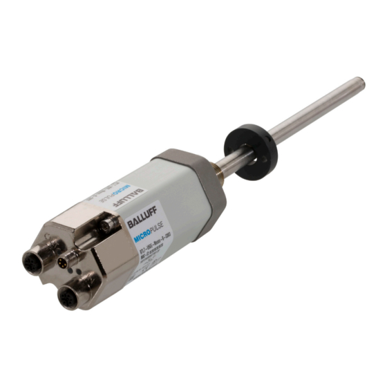
- Seite 1 All manuals and user guides at all-guides.com BTL7-V50E-M _ _ _ _ -A/B/Y/Z(8)-C003 Betriebsanleitung deutsch...
- Seite 2 All manuals and user guides at all-guides.com www.balluff.com...
-
Seite 3: Inhaltsverzeichnis
Maximale Abtastfrequenz f Zubehör Positionsgeber Befestigungsmutter Steckverbinder 7.3.1 Versorgungskabel, konfektioniert mit geradem M8-Stecker 7.3.2 Versorgungskabel, konfektioniert mit gewinkeltem M8-Stecker 7.3.3 Datenkabel, konfektioniert mit M12-Stecker 7.3.4 Datenkabel, konfektioniert mit RJ45-Stecker 7.3.5 Datenstecker gerade, frei konfektionierbar 7.3.6 Datenstecker gewinkelt, frei konfektionierbar www.balluff.com deutsch... - Seite 4 All manuals and user guides at all-guides.com BTL7-V50E-M _ _ _ _ -A/B/Y/Z(8)-C003 Micropulse Wegaufnehmer - Bauform Stab Typenschlüssel Anhang Umrechnung Längeneinheiten Typenschild deutsch...
-
Seite 5: Benutzerhinweise
– Magnetfelder EN 61000-4-8 Schärfegrad 4 Zulassungen und Kennzeichnungen Nähere Informationen zu Richtlinien, Zulas- sungen und Normen sind in der Konformitätser- UL-Zulassung klärung aufgeführt. File No. E227256 Eingetragene Marke und paten- tierte Technologie. Lizenziert durch die Beckhoff Automation GmbH, Deutschland. www.balluff.com deutsch... -
Seite 6: Sicherheit
Vermeidung von Gefahren. Anlage eingebaut. Die einwandfreie Funktion gemäß den Angaben in den technischen Daten wird nur mit original Die verwendeten Warnhinweise enthalten verschiedene BALLUFF-Zubehör zugesichert, die Verwendung anderer Signalwörter und sind nach folgendem Schema aufgebaut: Komponenten bewirkt Haftungsausschluss. SIGNALWORT Das Öffnen des Wegaufnehmers oder eine nicht bestim-... -
Seite 7: Aufbau Und Funktion
Positionsgeber: Definiert die zu messende Position auf dem Wellenleiter. Positionsgeber sind in unterschiedlichen Bauformen lieferbar und gesondert zu bestellen (siehe Zubehör auf Seite 15). Der Mindestabstand (L) zwischen den Positionsgebern muss mindestens 65 mm betragen. Bild 3-2: Abstand zwischen den Positionsgebern www.balluff.com deutsch... -
Seite 8: Funktion
All manuals and user guides at all-guides.com BTL7-V50E-M _ _ _ _ -A/B/Y/Z(8)-C003 Micropulse Wegaufnehmer - Bauform Stab Aufbau und Funktion (Fortsetzung) Funktion Im Wegaufnehmer BTL7 befindet sich der Wellenleiter, geschützt durch ein Edelstahlrohr. Entlang des Wellenlei- ters wird ein Positionsgeber bewegt. Dieser Positionsgeber ist mit dem Anlagenbauteil verbunden, dessen Position bestimmt werden soll. -
Seite 9: Led Anzeige
Tab. 3-2: LED 2 3.3.3 LED 3 / LED 4: Link/Activity LED 3/LED 4 (Grün) Zustand Verbindung Port offen Flackern Port offen Daten werden ausgetauscht Port geschlossen Nein Invertierter doppelter Blitz Port geschlossen (muss manuell geöffnet werden) Tab. 3-3: LED 3 und LED 4 www.balluff.com deutsch... -
Seite 10: Einbau Und Anschluss
All manuals and user guides at all-guides.com BTL7-V50E-M _ _ _ _ -A/B/Y/Z(8)-C003 Micropulse Wegaufnehmer - Bauform Stab Einbau und Anschluss Einbauvarianten Einbau vorbereiten Einbauvariante: Für die Aufnahme des Wegaufnehmers Nichtmagnetisierbares Material und des Positionsgebers empfehlen wir nichtmagnetisier- bares Material. nichtmagnetisierbares Material Waagerechte Montage: Bei waagerechter Montage mit Nennlängen > 500 mm empfehlen wir, den Stab am Ende anzuschrauben (nur bei Ø 10,2 mm möglich) oder abzu- stützen. -
Seite 11: Wegaufnehmer Einbauen
Möglich sind z. B. Torlon, Teflon oder Bronze. Gleitelement Distanzring Positionsgeber Bild 4-7: Fixierung Positionsgeber Ein Beispiel für den Einbau des Wegaufnehmers mit einem Stützrohr ist in Bild 4-8 auf Seite 9 dargestellt. Bild 4-5: Beispiel 1, Wegaufnehmer wird mit Gleitelement einge- baut www.balluff.com deutsch... -
Seite 12: Elektrischer Anschluss
All manuals and user guides at all-guides.com BTL7-V50E-M _ _ _ _ -A/B/Y/Z(8)-C003 Micropulse Wegaufnehmer - Bauform Stab Einbau und Anschluss (Fortsetzung) BUS IN/OUT (Daten) Positionsgeber (z. B. BTL-P-1028-15R) Kabelfarbe Signal YE gelb WH weiß OG orange TX− BU blau RX− Tab. 4-3: Pinbelegung Steckverbinder ...-C003, BUS IN/OUT Stützrohr aus nichtmagnetisierbarem Material Schirmung und Kabelverlegung Bild 4-8:... -
Seite 13: Inbetriebnahme
Hersteller die korrekten Werte im Nullpunkt und Endpunkt prüfen. Hinweise zum Betrieb – Funktion des Wegmesssystems und aller damit ver- bundenen Komponenten regelmäßig überprüfen. – Bei Funktionsstörungen das Wegmesssystem außer Betrieb nehmen. – Anlage gegen unbefugte Benutzung sichern. www.balluff.com deutsch... -
Seite 14: Technische Daten
Zustand) Für : Gebrauch in geschlossenen Räumen und bis zu einer Höhe von 2000 m über Meeresspiegel. Einzelbestimmung nach Balluff-Werknorm Für : Der Wegaufnehmer muss extern über einen energiebegrenzten Stromkreis gemäß UL 61010-1 oder eine Stromquelle begrenzter Leistung gemäß UL 60950-1 oder ein Netzteil der Schutzklasse 2 gemäß UL 1310 bzw. -
Seite 15: Zubehör
Betriebstemperatur: − 4 0 °C bis + 6 0 °C BTL-P-1013-4S BTL-P-1028-15R (Sonderzubehör für Applikationen mit Stützrohranwendung): Gewicht: ca. 68 g Gehäuse: Aluminium, eloxiert 120° BTL-P-1012-4R Ø 4.3 Bild 7-2: Sonderzubehör BTL-P-1028-15R BTL-P-1014-2R Befestigungsmutter – Befestigungsmutter M18×1.5: BTL-A-FK01-E-M18×1.5 – Befestigungsmutter 3/4“-16UNF: BTL-A-FK01-E-3/4“-16UNF Bild 7-1: Einbaumaße Positionsgeber www.balluff.com deutsch... -
Seite 16: Zubehör
All manuals and user guides at all-guides.com BTL7-V50E-M _ _ _ _ -A/B/Y/Z(8)-C003 Micropulse Wegaufnehmer - Bauform Stab Zubehör (Fortsetzung) Steckverbinder 7.3.2 Versorgungskabel, konfektioniert mit gewinkeltem M8-Stecker 7.3.1 Versorgungskabel, konfektioniert mit M8x1 geradem M8-Stecker – Steckverbinder gerade bzw. gewinkelt, umspritzt, konfektioniert – Buchse M8, 4-polig 32.2 Ø... -
Seite 17: Datenkabel, Konfektioniert Mit M12-Stecker
Bild 7-7: Steckerverbinder gerade - gerade Bestellcode BCC M414-E834-8G-668-PS54T2-020 BCC04K7 BCC M414-E834-8G-668-PS54T2-050 BCC04K8 BCC M414-E834-8G-668-PS54T2-100 BCC04K9 BCC M414-E834-8G-668-PS54T2-150 BCC04ZJ BCC M414-E834-8G-668-PS54T2-200 BCC04KA Beispiele: BCC M414-E834-8G-668-PS54T2-020 = Kabellänge 2 m BCC M414-E834-8G-668-PS54T2-050 = Kabellänge 5 m Bild 7-10: Datenkabel mit Stecker BCC M484-… www.balluff.com deutsch... - Seite 18 All manuals and user guides at all-guides.com BTL7-V50E-M _ _ _ _ -A/B/Y/Z(8)-C003 Micropulse Wegaufnehmer - Bauform Stab Typenschlüssel BTL7 - V 5 0 E - M0500 - B - C003 Wegaufnehmer Micropulse Ethernet-Schnittstelle Spannungsversorgung: 5 = 10…30 V DC Kennliniencharakteristik: 0 = konfigurierbar Ethernet-Schnittstellentyp: E = EtherCAT ®...
-
Seite 19: Anhang
1 inch = 25,4 mm inch inch 0,03937008 25,4 0,07874016 50,8 0,11811024 76,2 0,15748031 101,6 0,19685039 0,23622047 152,4 0,27559055 177,8 0,31496063 203,2 0,35433071 228,6 0,393700787 Tab. 9-1: Umrechnungstabelle mm-inch Tab. 9-2: Umrechnungstabelle inch-mm Typenschild Bestellcode Seriennummer Bild 9-1: Typenschild BTL7 www.balluff.com deutsch... - Seite 20 US Service Center CN Service Center Germany Germany China Balluff GmbH Balluff GmbH Balluff Inc. Balluff (Shanghai) trading Co., ltd. Schurwaldstrasse 9 Schurwaldstrasse 9 8125 Holton Drive Room 1006, Pujian Rd. 145. 73765 Neuhausen a.d.F. 73765 Neuhausen a.d.F. Florence, KY 41042 Shanghai, 200127, P.R.
- Seite 21 All manuals and user guides at all-guides.com BTL7-V50E-M _ _ _ _ -A/B/Y/Z(8)-C003 User’s Guide english...
- Seite 22 All manuals and user guides at all-guides.com www.balluff.com...
- Seite 23 7.3.1 Power cable, preassembled with straight M8 plug 7.3.2 Power cable, preassembled with angled M8 plug 7.3.3 Data cable, preassembled with M12 plug 7.3.4 Data cable, preassembled with RJ45 plug 7.3.5 Straight data plug, freely configurable 7.3.6 Angled data plug, freely configurable www.balluff.com english...
- Seite 24 All manuals and user guides at all-guides.com BTL7-V50E-M _ _ _ _ -A/B/Y/Z(8)-C003 Micropulse Transducer - Rod Style Type code breakdown Appendix Converting units of length Part label english...
-
Seite 25: Notes To The User
EN 61000-4-8 Severity level 4 Approvals and markings More detailed information on the guidelines, UL approval approvals, and standards is included in the File no. declaration of conformity. E227256 Registered trademark and patented technology. Licensed by Beckhoff Automation GmbH, Germany. www.balluff.com english... -
Seite 26: Safety
The warnings used here contain various signal words and specifications in the technical data is ensured only when are structured as follows: using original BALLUFF accessories. Use of any other SIGNAL WORD components will void the warranty. Hazard type and source... -
Seite 27: Construction And Function
Magnet: Defines the position to be measured on the waveguide. Magnets are available in various models and must be ordered separately (see Accessories on page 15). The distance (L) between the magnets must be at least 65 mm. Fig. 3-2: Distance between the magnets www.balluff.com english... -
Seite 28: Function
All manuals and user guides at all-guides.com BTL7-V50E-M _ _ _ _ -A/B/Y/Z(8)-C003 Micropulse Transducer - Rod Style Construction and function (continued) Function The BTL7 transducer contains the waveguide which is protected by an outer stainless steel tube (rod). A magnet is moved along the waveguide. This magnet is connected to the system part whose position is to be determined. -
Seite 29: Led Display
Tab. 3-2: LED 2 3.3.3 LED 3 / LED 4: Link/Activity LED 3/LED 4 (green) Status Connection Port open Flickering Port open Data is being exchanged Port closed Inverted double flash Port closed (must be opened manually) Tab. 3-3: LED 3 and LED 4 www.balluff.com english... -
Seite 30: Installation And Connection
All manuals and user guides at all-guides.com BTL7-V50E-M _ _ _ _ -A/B/Y/Z(8)-C003 Micropulse Transducer - Rod Style Installation and connection Installation guidelines Preparing for installation Installation note: We recommend using non- Non-magnetizable material magnetizable material to mount the transducer and magnet. Non-magnetizable material Horizontal assembly: If installing horizontally with nominal lengths > 500 mm, we recommend tightening the rod at the end (only possible with Ø 10.2 mm) or... -
Seite 31: Installing The Transducer
Slide element Magnet Spacer ring Fig. 4-7: Fixing of magnet An example of how to install the transducer with a supporting rod is shown in Fig. 4-8 on page 9. Fig. 4-5: Example 1, transducer installed with slide element www.balluff.com english... -
Seite 32: Electrical Connection
All manuals and user guides at all-guides.com BTL7-V50E-M _ _ _ _ -A/B/Y/Z(8)-C003 Micropulse Transducer - Rod Style Installation and connection (continued) BUS IN/OUT (data) Magnet (e.g. BTL-P-1028-15R) Cable color Signal YE yellow WH white OG orange TX− BU blue RX− Tab. 4-3: Pin assignment of ...-C003 connector, BUS IN/OUT Supporting rod made of non-magnetizable material Shielding and cable routing... -
Seite 33: Startup
Operating notes – Check the function of the transducer and all associated components on a regular basis. – Take the position measuring system out of operation whenever there is a malfunction. – Secure the system against unauthorized use. www.balluff.com english... -
Seite 34: Technical Data
: Use in enclosed spaces and up to a height of 2000 m above sea level. Individual specifications as per Balluff factory standard : The transducer must be externally connected via a limited- energy circuit as defined in UL 61010-1, a low-power source as defined in UL 60950-1, or a class 2 power supply as defined in UL 1310 or... -
Seite 35: Accessories
Weight: Approx. 68 g Housing: Anodized aluminum 120° BTL-P-1012-4R Ø 4.3 BTL-P-1014-2R Fig. 7-2: BTL-P-1028-15R special accessories Mounting nut – M18×1.5 mounting nut: BTL-A-FK01-E-M18×1.5 – 3/4”-16UNF mounting nut: BTL-A-FK01-E-3/4”-16UNF Fig. 7-1: Magnet installation dimensions www.balluff.com english... -
Seite 36: Connector
All manuals and user guides at all-guides.com BTL7-V50E-M _ _ _ _ -A/B/Y/Z(8)-C003 Micropulse Transducer - Rod Style Accessories (continued) Connector 7.3.2 Power cable, preassembled with angled M8 plug 7.3.1 Power cable, preassembled with straight M8 M8x1 plug – Straight or angled connector, molded, preassembled –... -
Seite 37: Data Cable, Preassembled With M12 Plug
BCC M414-E834-8G-668-PS54T2-020 BCC04K7 BCC M414-E834-8G-668-PS54T2-050 BCC04K8 BCC M414-E834-8G-668-PS54T2-100 BCC04K9 BCC M414-E834-8G-668-PS54T2-150 BCC04ZJ BCC M414-E834-8G-668-PS54T2-200 BCC04KA Examples: BCC M414-E834-8G-668-PS54T2-020 = cable length of 2 m Fig. 7-10: Data cable with BCC M484-… plug BCC M414-E834-8G-668-PS54T2-050 = cable length of 5 m www.balluff.com english... - Seite 38 All manuals and user guides at all-guides.com BTL7-V50E-M _ _ _ _ -A/B/Y/Z(8)-C003 Micropulse Transducer - Rod Style Type code breakdown BTL7 - V 5 0 E - M0500 - B - C003 Micropulse transducer Ethernet interface Supply voltage: 5 = 10 to 30 V DC Output gradient: 0 = Configurable Ethernet interface type:...
-
Seite 39: Converting Units Of Length
0.15748031 101.6 0.19685039 0.23622047 152.4 0.27559055 177.8 0.31496063 203.2 0.35433071 228.6 0.393700787 Tab. 9-1: Conversion table mm to inches Tab. 9-2: Conversion table inches to mm Part label Ordering code Type Serial number Fig. 9-1: BTL7 part label www.balluff.com english... - Seite 40 US Service Center CN Service Center Germany Germany China Balluff GmbH Balluff GmbH Balluff Inc. Balluff (Shanghai) trading Co., ltd. Schurwaldstrasse 9 Schurwaldstrasse 9 8125 Holton Drive Room 1006, Pujian Rd. 145. 73765 Neuhausen a.d.F. 73765 Neuhausen a.d.F. Florence, KY 41042 Shanghai, 200127, P.R.
- Seite 41 All manuals and user guides at all-guides.com BTL7-V50E-M _ _ _ _ -A/B/Y/Z(8)-C003 Manual de instrucciones español...
- Seite 42 All manuals and user guides at all-guides.com www.balluff.com...
- Seite 43 7.3.2 Cable de alimentación, confeccionado con conector M8 acodado 16 7.3.3 Cable de datos, confeccionado con conector M12 7.3.4 Cable de datos, confeccionado con conector RJ45 7.3.5 Conector de datos recto, libremente confeccionable 7.3.6 Conector de datos acodado, libremente confeccionable www.balluff.com español...
- Seite 44 All manuals and user guides at all-guides.com BTL7-V50E-M _ _ _ _ -A/B/Y/Z(8)-C003 Transductor de desplazamiento Micropulse - forma constructiva de varilla Código de modelo Anexo Conversión de unidades de longitud Placa de características español...
-
Seite 45: Indicaciones Para El Usuario
– Campos magnéticos Homologación UL EN 61000-4-8 Grado de File No. severidad 4 E227256 En la declaración de conformidad figura más información sobre las directivas, homologaciones y normas. Marca registrada y tecnología patentada. Con licencia de Beckhoff Automation GmbH, Alemania. www.balluff.com español... -
Seite 46: Seguridad
óptimo según las indicaciones que figuran en los datos Las advertencias utilizadas contienen diferentes palabras técnicos solo se garantiza con accesorios originales de de señalización y se estructuran según el siguiente BALLUFF; el uso de otros componentes provoca la esquema: exoneración de responsabilidad. PALABRA DE SEÑALIZACIÓN... -
Seite 47: Estructura Y Funcionamiento
(véase Accesorios en la página 15). La distancia mínima (L) entre los sensores de posición debe ser de 65 mm como mínimo. Fig. 3-2: Distancia entre los sensores de posición www.balluff.com español... -
Seite 48: Funcionamiento
All manuals and user guides at all-guides.com BTL7-V50E-M _ _ _ _ -A/B/Y/Z(8)-C003 Transductor de desplazamiento Micropulse - forma constructiva de varilla Estructura y funcionamiento (continuación) Funcionamiento En el transductor de desplazamiento BTL7 se encuentra el guíaondas, protegido mediante un tubo de acero inoxidable. -
Seite 49: Indicador Led
LED 3 / LED 4: Link/Activity LED 3/LED 4 (verde) Estado Conexión Puerto abierto Sí Centelleo Puerto abierto Sí Se produce intercambio de datos. Puerto cerrado Destello doble invertido Puerto cerrado (se debe abrir Sí manualmente) Tab. 3-3: LED 3 y LED 4 www.balluff.com español... -
Seite 50: Montaje Y Conexión
All manuals and user guides at all-guides.com BTL7-V50E-M _ _ _ _ -A/B/Y/Z(8)-C003 Transductor de desplazamiento Micropulse - forma constructiva de varilla Montaje y conexión Variantes de montaje Preparación del montaje Variante de montaje: para alojar el transductor de Material no imantable desplazamiento y el sensor de posición, recomendamos un material no imantable. -
Seite 51: Montaje Del Transductor De Desplazamiento
Fijación del sensor de posición En la figura 4-8 de la página 9 se representa un ejemplo de montaje del transductor de desplazamiento con un tubo de apoyo. Fig. 4-5: Ejemplo 1, el transductor de desplazamiento se monta con un elemento de deslizamiento www.balluff.com español... -
Seite 52: Conexión Eléctrica
All manuals and user guides at all-guides.com BTL7-V50E-M _ _ _ _ -A/B/Y/Z(8)-C003 Transductor de desplazamiento Micropulse - forma constructiva de varilla Montaje y conexión (continuación) BUS IN/OUT (datos) Sensor de posición (p. ej. BTL-P-1028-15R) Color del Señal cable YE amarillo WH blanco OG naranja TX−... -
Seite 53: Puesta En Servicio Del Sistema
Compruebe periódicamente el funcionamiento del sistema de medición de desplazamiento y todos los componentes relacionados. – Si se producen fallos de funcionamiento, ponga fuera de servicio el sistema de medición de desplazamiento. – Asegure la instalación contra cualquier uso no autorizado. www.balluff.com español... -
Seite 54: Datos Técnicos
2000 Hz Para : uso en espacios cerrados y hasta una altura de 2000 m sobre el nivel del mar. Grado de protección según Disposición individual según la norma de fábrica de Balluff IEC 60529 Conector C003 (atornillado) IP 67 Para : el transductor de desplazamiento se debe conectar externamente mediante un circuito eléctrico con limitación de energía de... -
Seite 55: Accesorios
Carcasa: Aluminio, anodizado BTL-P-1012-4R 120° Ø 4.3 BTL-P-1014-2R Fig. 7-2: Accesorios especiales BTL-P-1028-15R Tuerca de fijación – Tuerca de fijación M18×1.5: BTL-A-FK01-E-M18×1.5 – Tuerca de fijación 3/4"-16UNF: BTL-A-FK01-E-3/4"-16UNF Fig. 7-1: Medidas de montaje de los sensores de posición www.balluff.com español... -
Seite 56: Conectores
All manuals and user guides at all-guides.com BTL7-V50E-M _ _ _ _ -A/B/Y/Z(8)-C003 Transductor de desplazamiento Micropulse - forma constructiva de varilla Accesorios (continuación) Conectores 7.3.2 Cable de alimentación, confeccionado con conector M8 acodado 7.3.1 Cable de alimentación, confeccionado con M8x1 conector M8 recto –... -
Seite 57: Cable De Datos, Confeccionado Con Conector M12
BCC M414-E834-8G-668-PS54T2-020 BCC04K7 BCC M414-E834-8G-668-PS54T2-050 BCC04K8 BCC M414-E834-8G-668-PS54T2-100 BCC04K9 BCC M414-E834-8G-668-PS54T2-150 BCC04ZJ BCC M414-E834-8G-668-PS54T2-200 BCC04KA Ejemplos: BCC M414-E834-8G-668-PS54T2-020 = longitud de cable 2 m Fig. 7-10: Cable de datos con conector BCC M484-… BCC M414-E834-8G-668-PS54T2-050 = longitud de cable 5 m www.balluff.com español... -
Seite 58: Código De Modelo
All manuals and user guides at all-guides.com BTL7-V50E-M _ _ _ _ -A/B/Y/Z(8)-C003 Transductor de desplazamiento Micropulse - forma constructiva de varilla Código de modelo BTL7 - V 5 0 E - M0500 - B - C003 Transductor de desplazamiento Micropulse Interface Ethernet Alimentación de tensión: 5 = 10…30 V DC Características de la curva:... -
Seite 59: Conversión De Unidades De Longitud
0,23622047 152,4 0,27559055 177,8 0,31496063 203,2 0,35433071 228,6 0,393700787 Tab. 9-1: Tabla de conversión mm-pulgadas Tab. 9-2: Tabla de conversión pulgadas-mm Placa de características Código de pedido Tipo Número de serie Fig. 9-1: Placa de características del BTL7 www.balluff.com español... - Seite 60 US Service Center CN Service Center Germany Germany China Balluff GmbH Balluff GmbH Balluff Inc. Balluff (Shanghai) trading Co., ltd. Schurwaldstrasse 9 Schurwaldstrasse 9 8125 Holton Drive Room 1006, Pujian Rd. 145. 73765 Neuhausen a.d.F. 73765 Neuhausen a.d.F. Florence, KY 41042 Shanghai, 200127, P.R.
- Seite 61 All manuals and user guides at all-guides.com BTL7-V50E-M _ _ _ _ -A/B/Y/Z(8)-C003 Notice d’utilisation français...
- Seite 62 All manuals and user guides at all-guides.com www.balluff.com...
- Seite 63 7.3.1 Câble d’alimentation, confectionné avec connecteur M8 droit 7.3.2 Câble d’alimentation, confectionné avec connecteur M8 coudé 7.3.3 Câble de données, confectionné avec connecteur M12 7.3.4 Câble de données, confectionné avec connecteur RJ45 7.3.5 Connecteur de données droit, à assembler 7.3.6 Connecteur de données coudé, à assembler www.balluff.com français...
- Seite 64 All manuals and user guides at all-guides.com BTL7-V50E-M _ _ _ _ -A/B/Y/Z(8)-C003 Capteur de déplacement Micropulse - Forme à tige Code de type Annexe Conversion unités de longueur Plaque signalétique français...
-
Seite 65: Guide D'utilisation
Homologation UL – Champs magnétiques Dossier N° EN 61000-4-8 Degré de E227256 sévérité 4 Pour plus d’informations sur les directives, homologations et certifications, se reporter à la déclaration de conformité. Marque déposée et technologie brevetée. Licence certifiée par Beckhoff Automation GmbH, Allemagne. www.balluff.com français... -
Seite 66: Sécurité
MOT-CLE accessoires d’origine de BALLUFF, l’utilisation d’autres composants entraîne la nullité de la garantie. Type et source de danger Tout démontage du capteur de déplacement ou toute Conséquences en cas de non-respect du danger... -
Seite 67: Structure Et Fonction
Les capteurs de position peuvent être fournis sous différentes formes et doivent par conséquent être commandés séparément (voir Accessoires page 15). La distance minimale (L) entre les capteurs de position doit être de 65 mm. Fig. 3-2 : Distance entre les capteurs de position www.balluff.com français... -
Seite 68: Fonction
All manuals and user guides at all-guides.com BTL7-V50E-M _ _ _ _ -A/B/Y/Z(8)-C003 Capteur de déplacement Micropulse - Forme à tige Structure et fonction (suite) Fonction Le capteur de déplacement BTL7 abrite le guide d’ondes, qui est protégé par un tube en acier inoxydable. Un capteur de position se déplace le long du guide d’ondes. -
Seite 69: Affichage À Led
LED 3 / LED 4 : link / activity LED 3 / LED 4 (verte) Etat Connexion Allumée Port ouvert Vacillement Port ouvert Echange de données en cours Eteinte Port fermé Double flash inversé Port fermé (doit être ouvert manuellement) Tab. 3-3 : LED 3 et LED 4 www.balluff.com français... -
Seite 70: Montage Et Raccordement
All manuals and user guides at all-guides.com BTL7-V50E-M _ _ _ _ -A/B/Y/Z(8)-C003 Capteur de déplacement Micropulse - Forme à tige Montage et raccordement Variantes de montage Préparation du montage Variante de montage : pour la fixation des capteurs de Matériau non magnétisable déplacement et de position, nous recommandons l’utilisation de matériaux non magnétisables. -
Seite 71: Montage Du Capteur De Déplacement
Capteur de position Fig. 4-7 : Fixation du capteur de position Un exemple de montage du capteur de déplacement avec support est représenté sur la figure 4-8, page 9. Fig. 4-5 : Exemple 1, capteur de déplacement monté avec élément coulissant www.balluff.com français... -
Seite 72: Raccordement Électrique
All manuals and user guides at all-guides.com BTL7-V50E-M _ _ _ _ -A/B/Y/Z(8)-C003 Capteur de déplacement Micropulse - Forme à tige Montage et raccordement (suite) BUS IN / OUT (données) Capteur de position (p. ex. BTL-P-1028-15R) Broche Couleur de Signal câble YE jaune WH blanc OG orange TX−... -
Seite 73: Mise En Service Du Système
Conseils d’utilisation – Contrôler régulièrement les fonctions du système de mesure de déplacement et de tous ses composants. – En cas de dysfonctionnement, mettre le système hors service. – Protéger l’installation de toute utilisation non autorisée. www.balluff.com français... -
Seite 74: Caractéristiques Techniques
Pour : utilisation à l’intérieur et jusqu’à une altitude max. de 2000 m au-dessus du niveau de la mer. Détermination individuelle selon la norme d’usine Balluff. Pour : le capteur de déplacement doit être raccordé en externe par un circuit à énergie limitée, ainsi que défini dans la norme UL 61010-1, ou par une source basse tension UL 60950-1 ou encore par une alimentation... -
Seite 75: Accessoires
Aluminium anodisé 120° BTL-P-1012-4R Ø 4.3 Fig. 7-2 : Accessoire spécial BTL-P-1028-15R BTL-P-1014-2R Ecrous de fixation – Ecrou de fixation M18×1.5 : BTL-A-FK01-E-M18×1.5 – Ecrou de fixation 3/4"-16UNF : BTL-A-FK01-E-3/4"-16UNF Fig. 7-1 : Cotes de montage des capteurs de position www.balluff.com français... -
Seite 76: Connecteurs
All manuals and user guides at all-guides.com BTL7-V50E-M _ _ _ _ -A/B/Y/Z(8)-C003 Capteur de déplacement Micropulse - Forme à tige Accessoires (suite) Connecteurs 7.3.2 Câble d’alimentation, confectionné avec connecteur M8 coudé 7.3.1 Câble d’alimentation, confectionné avec M8x1 connecteur M8 droit – Connecteur droit ou coudé, extrudé, confectionné –... -
Seite 77: Câble De Données, Confectionné Avec Connecteur M12
BCC M414-E834-8G-668-PS54T2-020 BCC04K7 BCC M414-E834-8G-668-PS54T2-050 BCC04K8 BCC M414-E834-8G-668-PS54T2-100 BCC04K9 BCC M414-E834-8G-668-PS54T2-150 BCC04ZJ BCC M414-E834-8G-668-PS54T2-200 BCC04KA Exemples : BCC M414-E834-8G-668-PS54T2-020 = longueur de Fig. 7-10 : Câble de données avec connecteur BCC M484-… câble 2 m BCC M414-E834-8G-668-PS54T2-050 = longueur de câble 5 m www.balluff.com français... - Seite 78 All manuals and user guides at all-guides.com BTL7-V50E-M _ _ _ _ -A/B/Y/Z(8)-C003 Capteur de déplacement Micropulse - Forme à tige Code de type BTL7 - V 5 0 E - M0500 - B - C003 Capteur de déplacement Micropulse Interface Ethernet Alimentation électrique : 5 = 10 …...
-
Seite 79: Conversion Unités De Longueur
0,11811024 76,2 0,15748031 101,6 0,19685039 0,23622047 152,4 0,27559055 177,8 0,31496063 203,2 0,35433071 228,6 0,393700787 Tab. 9-1 : Conversion mm/pouce Tab. 9-2 : Conversion pouce/mm Plaque signalétique Symbolisation commerciale Type Numéro de série Fig. 9-1 : Plaque signalétique BTL7 www.balluff.com français... - Seite 80 US Service Center CN Service Center Germany Germany China Balluff GmbH Balluff GmbH Balluff Inc. Balluff (Shanghai) trading Co., ltd. Schurwaldstrasse 9 Schurwaldstrasse 9 8125 Holton Drive Room 1006, Pujian Rd. 145. 73765 Neuhausen a.d.F. 73765 Neuhausen a.d.F. Florence, KY 41042 Shanghai, 200127, P.R.
- Seite 81 All manuals and user guides at all-guides.com BTL7-V50E-M _ _ _ _ -A/B/Y/Z(8)-C003 Manuale d’uso italiano...
- Seite 82 All manuals and user guides at all-guides.com www.balluff.com...
- Seite 83 M8 diritto 7.3.2 Cavo di alimentazione, confezionato con connettore M8 ad angolo 7.3.3 Cavo dati, confezionato con connettore M12 7.3.4 Cavo dati, confezionato con connettore RJ45 7.3.5 Connettore dati diritto, confezionabile liberamente 7.3.6 Connettore dati ad angolo, confezionabile liberamente www.balluff.com italiano...
- Seite 84 All manuals and user guides at all-guides.com BTL7-V50E-M _ _ _ _ -A/B/Y/Z(8)-C003 Trasduttore di posizione Micropulse - versione a barra Legenda codici di identificazione Appendice Conversione delle unità di lunghezza Targhetta di identificazione italiano...
-
Seite 85: Avvertenze Per L'utente
Campi magnetici File No. EN 61000-4-8 Grado di E227256 definizione 4 Ulteriori informazioni in merito a direttive, autorizzazioni e norme sono indicate nella dichiarazione di conformità. Marchio registrato e tecnologia brevettata. Concesso in licenza da Beckhoff Automation GmbH, Germania. www.balluff.com italiano... -
Seite 86: Sicurezza
è garantito soltanto con accessori originali schema seguente: BALLUFF, l’uso di altri componenti comporta l’esclusione PAROLA DI SEGNALAZIONE della responsabilità. Natura e fonte del pericolo L’apertura o l’uso improprio del trasduttore di posizione... -
Seite 87: Struttura E Funzione
I datori di posizione sono disponibili in varie tipologie costruttive e devono essere ordinati separatamente (vedere Accessori da pagina 15). La distanza minima (L) tra i datori di posizione deve corrispondere ad almeno 65 mm. Fig. 3-2: Distanza tra i datori di posizione www.balluff.com italiano... -
Seite 88: Funzionamento
All manuals and user guides at all-guides.com BTL7-V50E-M _ _ _ _ -A/B/Y/Z(8)-C003 Trasduttore di posizione Micropulse - versione a barra Struttura e funzione (continua) Funzionamento Nel trasduttore di posizione BTL7 si trova la guida d’onda, protetta da un tubo in acciaio inox. Lungo la guida d’onda viene spostato un datore di posizione. -
Seite 89: Display Led
LED 3 / LED 4: Link/Activity LED 3/LED 4 (verde) Stato Connessione Acceso Porta aperta Sì Flicker Porta aperta Sì Scambio di dati in corso Spento Porta chiusa Lampeggio doppio invertito Porta chiusa Sì (deve essere aperta manualmente) Tab. 3-3: LED 3 e LED 4 www.balluff.com italiano... -
Seite 90: Montaggio E Collegamento
All manuals and user guides at all-guides.com BTL7-V50E-M _ _ _ _ -A/B/Y/Z(8)-C003 Trasduttore di posizione Micropulse - versione a barra Montaggio e collegamento Varianti di montaggio Preparazione del montaggio Variante di montaggio: per l’installazione del trasduttore Materiale non magnetizzabile e del datore di posizione si consiglia l’impiego di materiale non magnetizzabile. -
Seite 91: Montaggio Del Trasduttore Di Posizione
Fissaggio del datore di posizione Un esempio per il montaggio del trasduttore di posizione con un tubo di supporto è rappresentato nella figura 4-8 a pagina 9. Fig. 4-5: Esempio 1, il trasduttore di posizione viene montato con un elemento scorrevole www.balluff.com italiano... -
Seite 92: Collegamento Elettrico
All manuals and user guides at all-guides.com BTL7-V50E-M _ _ _ _ -A/B/Y/Z(8)-C003 Trasduttore di posizione Micropulse - versione a barra Montaggio e collegamento (continua) BUS IN/OUT (dati) Datore di posizione (p. es. BTL-P-1028-15R) Colore cavo Segnale YE giallo WH bianco OG arancione TX− BU blu RX−... -
Seite 93: Messa In Funzione Del Sistema
Controllare periodicamente il funzionamento del sistema di misura della corsa e di tutti i componenti ad esso collegati. – In caso di anomalie di funzionamento disattivare il sistema di misura della corsa. – Proteggere l’impianto da un uso non autorizzato. www.balluff.com italiano... -
Seite 94: Dati Tecnici
Connettore C003 (avvitato) IP 67 mare. Rilevazione singola secondo la norma interna Balluff : Il trasduttore di posizione deve essere collegato esternamente mediante un circuito elettrico ad energia limitata in base alla norma UL 61010-1 oppure mediante una fonte di energia a potenza limitata in base alla norma UL 60950-1 oppure un alimentatore della classe di protezione 2 in base alla norma UL 1310 o UL 1585. -
Seite 95: Accessori
Peso: ca. 68 g Supporto: alluminio anodizzato 120° BTL-P-1012-4R Ø 4.3 BTL-P-1014-2R Fig. 7-2: Accessori speciali BTL-P-1028-15R Dado di fissaggio – Dado di fissaggio M18×1.5: BTL-A-FK01-E-M18×1.5 – Dado di fissaggio 3/4“-16UNF: BTL-A-FK01-E-3/4“-16UNF Fig. 7-1: Dimensioni montaggio datore di posizione www.balluff.com italiano... -
Seite 96: Connettori
All manuals and user guides at all-guides.com BTL7-V50E-M _ _ _ _ -A/B/Y/Z(8)-C003 Trasduttore di posizione Micropulse - versione a barra Accessori (continua) Connettori 7.3.2 Cavo di alimentazione, confezionato con connettore M8 ad angolo 7.3.1 Cavo di alimentazione, confezionato con M8x1 connettore M8 diritto –... -
Seite 97: Cavo Dati, Confezionato Con Connettore M12
BCC M484-0000-2D-000-51X475-000 BCC03Y0 d’ordine BCC M414-E834-8G-668-PS54T2-020 BCC04K7 BCC M414-E834-8G-668-PS54T2-050 BCC04K8 BCC M414-E834-8G-668-PS54T2-100 BCC04K9 BCC M414-E834-8G-668-PS54T2-150 BCC04ZJ BCC M414-E834-8G-668-PS54T2-200 BCC04KA Esempi: BCC M414-E834-8G-668-PS54T2-020 = lunghezza cavo 2 m BCC M414-E834-8G-668-PS54T2-050 = lunghezza cavo 5 m Fig. 7-10: Cavo dati con connettore BCC M484-… www.balluff.com italiano... -
Seite 98: Legenda Codici Di Identificazione
All manuals and user guides at all-guides.com BTL7-V50E-M _ _ _ _ -A/B/Y/Z(8)-C003 Trasduttore di posizione Micropulse - versione a barra Legenda codici di identificazione BTL7 - V 5 0 E - M0500 - B - C003 Trasduttore di posizione Micropulse Interfaccia Ethernet Tensione di alimentazione: 5 = 10…30 V DC Curva caratteristica:... -
Seite 99: Conversione Delle Unità Di Lunghezza
101,6 0,19685039 0,23622047 152,4 0,27559055 177,8 0,31496063 203,2 0,35433071 228,6 0,393700787 Tab. 9-1: Tabella di conversione mm-pollici Tab. 9-2: Tabella di conversione pollici-mm Targhetta di identificazione Codice d’ordine Tipo Numero di serie Fig. 9-1: Targhetta di identificazione BTL7 www.balluff.com italiano... - Seite 100 US Service Center CN Service Center Germany Germany China Balluff GmbH Balluff GmbH Balluff Inc. Balluff (Shanghai) trading Co., ltd. Schurwaldstrasse 9 Schurwaldstrasse 9 8125 Holton Drive Room 1006, Pujian Rd. 145. 73765 Neuhausen a.d.F. 73765 Neuhausen a.d.F. Florence, KY 41042 Shanghai, 200127, P.R.