Balluff Light Array BLA 50A-001-S115 Betriebsanleitung
Inhaltsverzeichnis
Verfügbare Sprachen
Verfügbare Sprachen
Quicklinks
Inhaltsverzeichnis

Verwandte Anleitungen für Balluff Light Array BLA 50A-001-S115


Inhaltszusammenfassung für Balluff Light Array BLA 50A-001-S115
- Seite 1 BLA 50A-001-S115 Balluff Light Array Betriebsanleitung deutsch...
- Seite 2 Copyright © Balluff GmbH, Neuhausen a.d.F., Deutschland, 2016. Alle Rechte vorbehalten. Insbesondere: Recht der Vervielfäl- tigung, Veränderung, Verbreitung und Übersetzung in andere Sprachen. Kommerzielle Vervielfältigungen, Reproduktionen, Veränderungen und Verbreitungen jeglicher Form bedürfen der vorherigen schriftlichen Zustimmung durch die Balluff GmbH. Liefermöglichkeiten und technische Änderungen vorbehalten.
-
Seite 3: Inhaltsverzeichnis
BLA 50A-001-S115 Balluff Light Array Benutzerhinweise Über diese Anleitung Aufbau der Anleitung Verwendete Symbole und Konventionen Lieferumfang Zulassungen und Kennzeichnungen Sicherheit Funktionsüberblick Bestimmungsgemäße Verwendung Sicherheitshinweise Bedeutung der Warnhinweise Entsorgung Montage Befestigung Elektrische Anschlüsse Montagetoleranzen Ausrichtung 3.4.1 Ausrichtung ohne Hilfsmittel 3.4.2 Ausrichtung mittels elektronischer Ausrichthilfe 3.4.3 Signalnormierung... -
Seite 4: Benutzerhinweise
Dieses Handbuch beinhaltet Bedienanweisungen und Mit dem CE-Zeichen bestätigen wir, dass technische Dokumentation für den Sender und den Emp- die Geräte den Anforderungen der EG– fänger des Balluff Light Array BLA. Richtlinien 2004/108/EWG (EMC) und Alle Angaben in diesem Bedienungshandbuch, insbeson- des EMV-Gesetzes entsprechen. -
Seite 5: Sicherheit
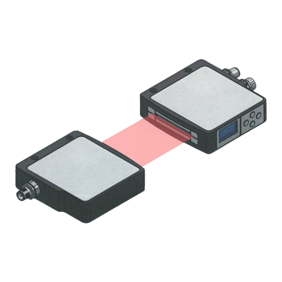
BLA 50A-001-S115 Balluff Light Array Sicherheit – Nicht in explosionsgefährdeten Bereichen verwenden! Funktionsüberblick Gefahr der Zündung! – Die Geräte sind während des Anschlusses, der Inbe- – Paralleles LASER-Lichtband mit einer aktiven Breite triebnahme und des Betriebs vor Feuchtigkeit und von 50 mm Verunreinigung zu schützen. -
Seite 6: Montage
BLA 50A-001-S115 Balluff Light Array Montage Ader- Funktion Bemerkung Befestigung farben Montagehinweise weiss Digitalaus- – Montieren Sie die Geräte fest an einer stabilen, vibrati- gang 1 onsfreien Halterung. braun 15…30 V – Richten Sie die Geräte so aus, dass die Bedienele- grün... -
Seite 7: Ausrichtung
BLA 50A-001-S115 Balluff Light Array Montage (Fortsetzung) Bild 3-4: Lichtband zu weit rechts Bild 3-5: Lichtband zu tief 3.4.2 Ausrichtung mittels elektronischer Drehwinkel Ausrichthilfe Die korrekte Ausrichtung kann auch elektronisch überprüft werden. Dazu wählen Sie im Hauptmenü Device settings → Live (siehe Kap. -
Seite 8: Bedienung Und Auswahl Der Messmodi
BLA 50A-001-S115 Balluff Light Array Bedienung und Auswahl der Messmodi Beschriftung Funktion Einfühung In die übergeordnete Menüebene Nach dem Einschalten ist das Gerät funktionsbereit und zurück springen zeigt die aktuellen Messwerte und die gewählten Mess- modi an. ∧ In der Liste aufwärts blättern;... -
Seite 9: Menüstruktur
BLA 50A-001-S115 Balluff Light Array Bedienung und Auswahl der Messmodi (Fortsetzung) Menüstruktur Konfiguration der Analogausgänge Wenn im Display die Messwert-Anzeige sichtbar ist, Beide Analogausgänge können unabhängig voneinander erreicht man durch Drücken der OK (Enter)-Taste das konfiguriert werden. Die Einstellmöglichkeiten sind für Hauptmenü. -
Seite 10: Eine Kante
BLA 50A-001-S115 Balluff Light Array Bedienung und Auswahl der Messmodi (Fortsetzung) Es stehen folgende Modi zur Verfügung: Mode Kürzel Beschreibung Left Obj. Für Bahnkantensteuerung. Objekt wird von links (L) in den aktiven Bereich eingebracht. Es wird der Abstand der vorderen / führenden Kante vom linken Messfeldrand ausgegeben. -
Seite 11: Konfiguration Der Objekterkennung Oder -Zählung (Digitalausgänge)
BLA 50A-001-S115 Balluff Light Array Bedienung und Auswahl der Messmodi (Fortsetzung) 4.4.2 Objekt-Modus Bild 4-7: Objekt-Modus Für den Objektmodus (Object mode) können die gleichen Messmodi wie bei den Analogausgängen gewählt werden. Auswählbare Modi für die Objekteerkennung und -unter- scheidung sind: Left Obj. -
Seite 12: Zählende Modi
BLA 50A-001-S115 Balluff Light Array Bedienung und Auswahl der Messmodi (Fortsetzung) Nummer des aktuell im Licht- Die eingelernten Objekte gelten nur für erken- weg befindlichen Objekts nende Modi, nicht für zählende Modi. Einge- lernte Objekte bleiben aber gespeichert, wenn man auf einen zählenden Modus (Count Obj. -
Seite 13: Messfeld Einschränken (Blanking)
BLA 50A-001-S115 Balluff Light Array Bedienung und Auswahl der Messmodi (Fortsetzung) Messfeld einschränken (Blanking) Damit kann die Größe des Messfeldes manuell einge- schränkt werden. Dadurch können störende Objekte ausgeblendet werden. Für den rechten und linken Rand kann jeweils ein Bereich in 0,1-mm-Schritten festgelegt Bild 4-10: Messwertanzeige: Einstellungsbeispiel Count Objects (CO) -
Seite 14: Normierung Und Livebild
BLA 50A-001-S115 Balluff Light Array Normierung und Livebild (typ. unter 15 ms). Der Kehrwert der Abtastperiode ent- Livebild (Monitor) spricht der Schaltfrequenz. Mit der Livebild-Funktion kann das aktuelle CCD-Signal angezeigt werden. Bild 5-3: Statusinfo-Anzeige Bild 5-1: Livebild mit zwei Objekten im Lichtband A1/A2 Calibrate U/I Mit dieser Funktion können die beiden Analogausgänge so... -
Seite 15: Technische Daten
BLA 50A-001-S115 Balluff Light Array Technische Daten Abmessungen Abmessungen BLA Empfänger Bild 6-1: Abmessungen BLA Sender LED Anzeigen 1 LED grün: Betriebsan- Mechanische Daten zeige; Werkstoff Gehäuse Aluminium eloxiert 1 LED orange: Objekt- anzeige Werkstoff aktive Fläche Sender: Antireflex-be- schichtetes Glas Abtastperiode 1,3 ms…100 ms... -
Seite 16: Umgebungsbedingungen
–25…+70 °C Verpolungssicher Kurzschlussfest Pflege und Wartung Das Balluff Light Array benötigt, abgesehen von der Reini- gung der die Optik schützenden vorderseitigen Oberflächen, nur minimale Wartung. Sender- und Empfängerfenster sind frei von Verschmut- zung (Staub, Fingerabdrücken ect.) zu halten. Falls eine Reinigung nötig ist, so können die Fenster mit einem...