Balluff BTL7-A Serie Betriebsanleitung
Magnetostriktives positionsmesssystem; bauform stab
Vorschau ausblenden
Andere Handbücher für BTL7-A Serie:
- Betriebsanleitung (154 Seiten) ,
- Kurzanleitung (17 Seiten) ,
- Betriebsanleitung (27 Seiten)
Inhaltsverzeichnis
Werbung
Verfügbare Sprachen
Verfügbare Sprachen
Quicklinks
Werbung
Inhaltsverzeichnis

Verwandte Anleitungen für Balluff BTL7-A Serie


Inhaltszusammenfassung für Balluff BTL7-A Serie
- Seite 1 BTL7-A/C/E/G_ _ _-M_ _ _ _-A(8)-SA211-S32/S115/S135/KA_ _/FA_ _ BTL7-A/C/E/G_ _ _-M_ _ _ _-A(8)-SA311-S32/S115/S135/KA_ _/FA_ _ Betriebsanleitung deutsch english User’s guide français Notice d’utilisation italiano Manuale d’uso español Manual de instrucciones...
- Seite 2 www.balluff.com...
- Seite 3 BTL7-A/C/E/G _ _ _ -M _ _ _ _ -A(8)-SA211-S32/S115/S135/KA_ _/FA_ _ BTL7-A/C/E/G _ _ _ -M _ _ _ _ -A(8)-SA311-S32/S115/S135/KA_ _/FA_ _ Betriebsanleitung deutsch...
- Seite 4 www.balluff.com...
-
Seite 5: Inhaltsverzeichnis
4.4.2 Steckverbinder S115 4.4.3 Steckverbinder S135 Schirmung und Kabelverlegung Inbetriebnahme System in Betrieb nehmen Hinweise zum Betrieb Einstellverfahren Einstellvorrichtung Programmiereingänge (nicht bei BTL7-…-S135) Übersicht der Einstellverfahren 6.3.1 Teach-in 6.3.2 Justieren 6.3.3 Online-Setting 6.3.4 Reset Auswahl des Einstellverfahrens Hinweise zum Einstellvorgang www.balluff.com deutsch... - Seite 6 BTL7-A/C/E/G _ _ _ -M _ _ _ _ -A(8)-SA211/SA311-S32/S115/S135/KA_ _/FA_ _ Magnetostriktives Positionsmesssystem – Bauform Stab Einstellen durch Teach-in Einstellen durch Justieren Einstellen durch Online-Setting Rücksetzen aller Werte (Reset) Technische Daten 11.1 Genauigkeit 11.2 Umgebungsbedingungen 11.3 Spannungsversorgung (extern) 11.4 Ausgang 11.5 Eingang 11.6 Maße, Gewichte Zubehör...
-
Seite 7: Benutzerhinweise
Konformitätserklärung aufgeführt. Lieferumfang – – Einstellvorrichtung – Kurzanleitung Die Positionsgeber sind in unterschiedlichen Bauformen lieferbar und deshalb gesondert zu bestellen. Zulassungen und Kennzeichnungen Nicht bei BTL7-…-FA_ _ US-Patent 5 923 164 Das US-Patent wurde in Verbindung mit diesem Produkt erteilt. www.balluff.com deutsch... -
Seite 8: Sicherheit
Industriebereich vorgesehen. Die einwandfreie Funktion Die verwendeten Warnhinweise enthalten verschiedene gemäß den Angaben in den technischen Daten wird nur Signalwörter und sind nach folgendem Schema aufgebaut: mit original Balluff Zubehör zugesichert, die Verwendung anderer Komponenten bewirkt Haftungsausschluss. SIGNALWORT Art und Quelle der Gefahr Das Öffnen des BTL oder eine nichtbestimmungsgemäße... -
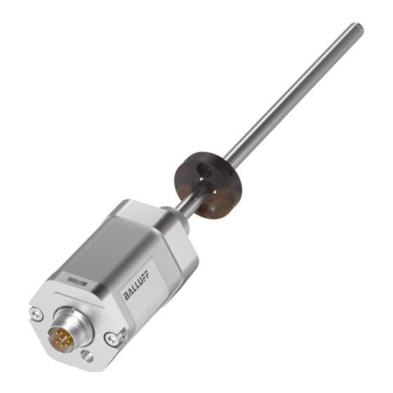
Seite 9: Aufbau Und Funktion
Befestigungsgewinde zu montieren: – BTL7-…-A: M18×1.5 Dämpfungszone: Messtechnisch nicht nutzbarer Bereich Das BTL mit Ø 10,2 mm besitzt am Stabende ein zusätzli- am Stabende, der überfahren werden darf. ches Gewinde zum Abstützen bei großen Nennlängen. Einstellvorrichtung: Zusatzeinrichtung zum Einstellen des BTL. www.balluff.com deutsch... -
Seite 10: Funktion
BTL7-A/C/E/G _ _ _ -M _ _ _ _ -A(8)-SA211/SA311-S32/S115/S135/KA_ _/FA_ _ Magnetostriktives Positionsmesssystem – Bauform Stab Aufbau und Funktion (Fortsetzung) Funktion LED-Anzeige Im BTL befindet sich der Wellenleiter, geschützt durch ein LED 1 LED 2 Edelstahlrohr. Entlang des Wellenleiters wird ein Positions- geber bewegt. -
Seite 11: Einbau Und Anschluss
Positionsgeber zur Verfügung (siehe Zubehör auf Seite 24). Positionsgeber Distanzring aus nichtmagnetisierbarem Material min. Ø D2 = Mindestdurchmesser der Bohrung (siehe Tab. 4-1) Bild 4-2: Einbauvarianten in magnetisierbares Material Stabdurchmesser Bohrungsdurchmesser D2 10,2 mm mindestens 13 mm 8 mm mindestens 11 mm Tab. 4-1: Bohrungsdurchmesser bei Einbau in einen Hydraulikzylinder www.balluff.com deutsch... -
Seite 12: Btl Einbauen
BTL7-A/C/E/G _ _ _ -M _ _ _ _ -A(8)-SA211/SA311-S32/S115/S135/KA_ _/FA_ _ Magnetostriktives Positionsmesssystem – Bauform Stab Einbau und Anschluss (Fortsetzung) Das Gleitelement kann aufgeschraubt oder aufgeklebt BTL einbauen werden. ► Schraube gegen Lösen oder Verlieren sichern. ACHTUNG ► Geeigneten Klebstoff auswählen. Funktionsbeeinträchtigung Gleitfläche Durchflussspalt... -
Seite 13: Elektrischer Anschluss
20…0 mA 4…20 mA 20…4 mA Lb (Programmiereingang) BTL7-_1_ _-… BTL7-_5_ _-… 20…28 V 10…30 V Nicht belegte Adern können steuerungsseitig mit GND verbunden werden, aber nicht mit dem Schirm. Bezugspotenzial für Betriebs spannung und EMV-GND. Tab. 4-3: Anschlussbelegung BTL7…-S115 www.balluff.com deutsch... -
Seite 14: Steckverbinder S135
BTL7-A/C/E/G _ _ _ -M _ _ _ _ -A(8)-SA211/SA311-S32/S115/S135/KA_ _/FA_ _ Magnetostriktives Positionsmesssystem – Bauform Stab Einbau und Anschluss (Fortsetzung) 4.4.3 Steckverbinder S135 S135 -A_10 -G_10 -C_00 -C_70 -E_00 -E_70 0…10 V –10…10 V 0…20 mA 20…0 mA 4…20 mA 20…4 mA 0 V (Pin 1) Bild 4-10: Pinbelegung S135 (Draufsicht auf 10…0 V... -
Seite 15: Inbetriebnahme
Reparatur durch den Hersteller die korrekten Werte im Nullpunkt und Endpunkt prüfen. Hinweise zum Betrieb – Funktion des BTL und aller damit verbundenen Kom- ponenten regelmäßig überprüfen. – Bei Funktionsstörungen das BTL außer Betrieb neh- men. – Anlage gegen unbefugte Benutzung sichern. www.balluff.com deutsch... -
Seite 16: Einstellverfahren
BTL7-A/C/E/G _ _ _ -M _ _ _ _ -A(8)-SA211/SA311-S32/S115/S135/KA_ _/FA_ _ Magnetostriktives Positionsmesssystem – Bauform Stab Einstellverfahren Einstellvorrichtung Übersicht der Einstellverfahren Die Einstellvorrichtung ist eine Zusatzeinrichtung zum 6.3.1 Teach-in Einstellen des BTL. ► Vor Beginn der Einstellung: Einstellvorrichtung auf die Der werkseitig eingestellte Null- und Endpunkt wird durch Anschlussseite des BTL aufsetzen. -
Seite 17: Justieren
End- Null- End- einstellen. punkt punkt punkt punkt Taster inaktiv Neuer Endwert Taster aktiv vorher Online- Online- Setting Setting nachher Endpunkt Nullpunkt Endpunkt Bild 6-6: Auswahl des Einstellverfahrens Bild 6-5: Neue Endposition justieren (Änderung der Steigung der Kennlinie) www.balluff.com deutsch... -
Seite 18: Hinweise Zum Einstellvorgang
BTL7-A/C/E/G _ _ _ -M _ _ _ _ -A(8)-SA211/SA311-S32/S115/S135/KA_ _/FA_ _ Magnetostriktives Positionsmesssystem – Bauform Stab Einstellverfahren (Fortsetzung) Hinweise zum Einstellvorgang Voraussetzungen – Einstellvorrichtung ist aufgesetzt oder Programmierein- gänge sind angeschlossen. – BTL ist mit der Anlagensteuerung verbunden. – Spannungs- oder Stromwerte des BTL können gelesen werden (mittels Multimeter oder Anlagensteuerung). -
Seite 19: Einstellen Durch Teach-In
< 1 s ⇒ Taster sind deaktiviert. 10.00 V 20.00 mA ⇒ Aktueller Positionswert wird angezeigt. Legende LED: LED leuchtet nicht LED grün blinkend LED grün leuchtend LED rot leuchtend LED 1 und LED 2 grün-grün alternierend blinkend www.balluff.com deutsch... -
Seite 20: Einstellen Durch Justieren
BTL7-A/C/E/G _ _ _ -M _ _ _ _ -A(8)-SA211/SA311-S32/S115/S135/KA_ _/FA_ _ Magnetostriktives Positionsmesssystem – Bauform Stab Einstellen durch Justieren ACHTUNG Funktionsbeeinträchtigung LED-Anzeige Angezeigte Werte (Beispiel) Das Justieren während des Betriebs der Anlage kann zu Fehlfunktionen führen. LED1 LED2 bei 0…10 V bei 4…20 mA ►... - Seite 21 1 µA erhöht bzw. verringert. Wird ein Taster länger als 1 s gedrückt gehalten, LED grün leuchtend LED 1 und LED 2 rot-grün alternierend blinkend erhöht sich die Schrittweite. LED grün blinkend LED 1 und LED 2 rot-rot alternierend blinkend www.balluff.com deutsch...
-
Seite 22: Einstellen Durch Online-Setting
BTL7-A/C/E/G _ _ _ -M _ _ _ _ -A(8)-SA211/SA311-S32/S115/S135/KA_ _/FA_ _ Magnetostriktives Positionsmesssystem – Bauform Stab Einstellen durch Online-Setting Beim Online-Setting wird die Anlage nicht außer Betrieb ACHTUNG genommen. Anfangs- und Endwert werden online einge- stellt. Funktionsbeeinträchtigung Maximaler Einstellbereich je Einstellvorgang: Die Änderung des BTL-Ausgangssignals kann bei einer Anfangswert: ±25 % vom aktuellen Hub betriebsbereiten Anlage zu Personen- und Sachschäden... -
Seite 23: Rücksetzen Aller Werte (Reset)
⇒ Alle Werte sind zurückgesetzt. ► Taster loslassen. ⇒ Aktueller Positionswert wird angezeigt. 8.43 V 15.67 mA ⇒ Taster sind verriegelt. Legende LED: LED leuchtet nicht LED grün leuchtend LED grün blinkend LED 1 und LED 2 im Gleichtakt grün-rot blinkend www.balluff.com deutsch... -
Seite 24: Technische Daten
Für UL: Gebrauch in geschlossenen Räumen und bis zu einer Höhe von bei Ø 8 mm ≤ 250 bar 2000 m über Meeresspiegel. bei Ø 10,2 mm ≤ 600 bar Einzelbestimmung nach Balluff Werknorm Schockbelastung 150 g/6 ms Resonanzfrequenzen ausgenommen Dauerschock 50 g/2 ms Für UL: Das BTL muss extern über einen energiebegrenzten Stromkreis nach EN 60068-2-27... -
Seite 25: Maße, Gewichte
Kabelmaterial cULus 20549 80 °C, 300 V, internal wiring Kabeltemperatur –40…+90 °C Kabeldurchmesser max. 7 mm zulässiger Biegeradius feste Verlegung ≥ 35 mm bewegt ≥ 105 mm BTL7-…-FA_ _ Kabelmaterial PTFE keine UL-Zulassung verfügbar Kabeltemperatur –55…+200 °C Kabeldurchmesser max. 7 mm zulässiger Biegeradius feste Verlegung ≥ 35 mm bewegt kein zulässiger Biegeradius www.balluff.com deutsch... -
Seite 26: Zubehör
BTL7-A/C/E/G _ _ _ -M _ _ _ _ -A(8)-SA211/SA311-S32/S115/S135/KA_ _/FA_ _ Magnetostriktives Positionsmesssystem – Bauform Stab Zubehör Zubehör ist nicht im Lieferumfang enthalten und deshalb BTL-P-1013-4R, BTL-P-1013-4S, BTL-P-1012-4R, getrennt zu bestellen. BTL-P-1014-2R: Gewicht: < 15 g 12.1 Positionsgeber Gehäuse: Aluminium BTL-P-1013-4R Im Lieferumfang der Positionsgeber BTL-P-1013-4R, BTL-P-1013-4S, BTL-P-1012-4R enthalten:... -
Seite 27: Steckverbinder S32
Steckverbinder gewinkelt, M16 nach IEC 130-9, 8-polig ~ 54 48.5 Bild 12-5: Steckverbinder S32 (konfektioniert) Ø 20 Farbe Bild 12-3: Steckverbinder BKS-S 33M-00 YE Gelb GY Grau PK Rosa RD Rot GN Grün BU Blau BN Braun WH Weiß Tab. 12-1: Pinbelegung S32 (konfektioniert) www.balluff.com deutsch... -
Seite 28: Steckverbinder S115, Konfektioniert
BTL7-A/C/E/G _ _ _ -M _ _ _ _ -A(8)-SA211/SA311-S32/S115/S135/KA_ _/FA_ _ Magnetostriktives Positionsmesssystem – Bauform Stab Zubehör (Fortsetzung) 12.4 Steckverbinder S115, konfektioniert 12.5 Steckverbinder S135, frei konfektionierbar BKS-S115-PU-_ _ BKS-S135M-00 Steckverbinder gerade, angespritzt, M12, 8-polig Bestellcode: BCC00Z6 Unterschiedliche Kabellängen bestellbar, z. B. Steckverbinder gerade, frei konfektionierbar BKS-S115-PU-05 (Bestellcode BCC00YF): Kabel- M16 nach IEC 130-9, 6-polig... -
Seite 29: Stecksystem, 8-Polig
Stecksystem am Beispiel Einbau des BTL in einen Hydrau- likzylinder Baureihe ZA10 Material Vierkantflansch: Messing vernickelt BTL7-…-KA00,2-ZA10, PUR-Kabel 0,2 m BTL7-…-KA00,3-ZA10, PUR-Kabel 0,3 m Baureihe ZA15 Material Vierkantflansch: Edelstahl BTL7-…-KA00,2-ZA15, PUR-Kabel 0,2 m BTL7-…-KA00,3-ZA15, PUR-Kabel 0,3 m +0.10 13.3 -0.00 Ø 3.2 Bild 12-13: Vierkantflansch www.balluff.com deutsch... -
Seite 30: Typenschlüssel
BTL7-A/C/E/G _ _ _ -M _ _ _ _ -A(8)-SA211/SA311-S32/S115/S135/KA_ _/FA_ _ Magnetostriktives Positionsmesssystem – Bauform Stab Typenschlüssel BTL7 - A110 - M0500 - A - SA211 - S32 Schnittstelle: A = Analogschnittstelle, Spannungsausgang 0…10 V G = Analogschnittstelle, Spannungsausgang –10…+10 V C = Analogschnittstelle, Stromausgang 0…20 mA E = Analogschnittstelle, Stromausgang 4…20 mA Betriebsspannung:... -
Seite 31: Anhang
Typenschild 1 mm = 0.0393700787 inch inch 0.03937008 0.07874016 0.11811024 0.15748031 0.19685039 0.23622047 0.27559055 0.31496063 0.35433071 0.393700787 Tab. 14-1: Umrechnungstabelle mm-inch Bestellcode Seriennummer 1 inch = 25,4 mm Bild 14-1: Typenschild BTL7 (Beispiel) inch 25,4 50,8 76,2 101,6 152,4 177,8 203,2 228,6 Tab. 14-2: Umrechnungstabelle inch-mm www.balluff.com deutsch... - Seite 33 BTL7-A/C/E/G _ _ _ -M _ _ _ _ -A(8)-SA211-S32/S115/S135/KA_ _/FA_ _ BTL7-A/C/E/G _ _ _ -M _ _ _ _ -A(8)-SA311-S32/S115/S135/KA_ _/FA_ _ User’s Guide english...
- Seite 34 www.balluff.com...
- Seite 35 Shielding and cable routing Startup Starting up the system Operating notes Calibration procedure Calibration device Programming inputs (not for BTL7-…-S135) Calibration procedure overview 6.3.1 Teach-in 6.3.2 Adjusting 6.3.3 Online setting 6.3.4 Reset Selecting the calibration procedure Calibration procedure notes www.balluff.com english...
- Seite 36 BTL7-A/C/E/G _ _ _ -M _ _ _ _ -A(8)-SA211/SA311-S32/S115/S135/KA_ _/FA_ _ Magnetostrictive Linear Position Sensor – Rod Style Calibration using teach-in Calibration using adjustment Calibration using online setting Resetting all values (reset) Technical data 11.1 Accuracy 11.2 Ambient conditions 11.3 Supply voltage (external) 11.4 Output 11.5 Input...
-
Seite 37: Notes To The User
– Calibration device – Condensed guide The magnets are available in various models and must be ordered separately. Approvals and markings Not for BTL7-…-FA_ _ US Patent 5 923 164 The US patent was awarded in connection with this product. www.balluff.com english... -
Seite 38: Safety
The warnings used here contain various signal words and Flawless function in accordance with the specifications in are structured as follows: the technical data is ensured only when using original Balluff accessories. Use of any other components will void SIGNAL WORD the warranty. Hazard type and source... -
Seite 39: Construction And Function
Damping zone: Area at the end of the rod that cannot be used for measurements, but which may be passed over. Calibration device: Additional device for calibrating the BTL. www.balluff.com english... -
Seite 40: Function
BTL7-A/C/E/G _ _ _ -M _ _ _ _ -A(8)-SA211/SA311-S32/S115/S135/KA_ _/FA_ _ Magnetostrictive Linear Position Sensor – Rod Style Construction and function (continued) Function LED display The BTL contains the waveguide which is protected by an LED 1 LED 2 outer stainless steel tube (rod). A magnet is moved along the waveguide. -
Seite 41: Installation And Connection
Min. Ø D2 = Minimum diameter of the hole (see Tab. 4-1) Figure 4-2: Installation in magnetizable material Rod diameter Bore diameter D2 10.2 mm At least 13 mm 8 mm At least 11 mm Tab. 4-1: Bore diameter if installed in a hydraulic cylinder www.balluff.com english... -
Seite 42: Installing The Btl
BTL7-A/C/E/G _ _ _ -M _ _ _ _ -A(8)-SA211/SA311-S32/S115/S135/KA_ _/FA_ _ Magnetostrictive Linear Position Sensor – Rod Style Installation and connection (continued) The slide element can be screwed on or bonded. Installing the BTL ► Secure the screws so they cannot be loosened or lost. ►... -
Seite 43: Electrical Connection
BTL7-_1_ _-… BTL7-_5_ _-… 20 to 28 V 10 to 30 V Unassigned leads can be connected to the GND on the controller side but not to the shield. Reference potential for supply voltage and EMC-GND. Tab. 4-3: Connection assignment BTL7...-S115 www.balluff.com english... -
Seite 44: Connector S135
BTL7-A/C/E/G _ _ _ -M _ _ _ _ -A(8)-SA211/SA311-S32/S115/S135/KA_ _/FA_ _ Magnetostrictive Linear Position Sensor – Rod Style Installation and connection (continued) 4.4.3 Connector S135 S135 -A_10 -G_10 -C_00 -C_70 -E_00 -E_70 0…10 V –10…10 V 0…20 mA 20…0 mA 4…20 mA 20…4 mA 0 V (pin 1) Figure 4-10: Pin assignment of S135 (view from... -
Seite 45: Startup
BTL or after repair by the manufacturer. Operating notes – Regularly check function of the BTL and all associated components. – Take the BTL out of operation whenever there is a malfunction. – Secure the system against unauthorized use. www.balluff.com english... -
Seite 46: Calibration Procedure
BTL7-A/C/E/G _ _ _ -M _ _ _ _ -A(8)-SA211/SA311-S32/S115/S135/KA_ _/FA_ _ Magnetostrictive Linear Position Sensor – Rod Style Calibration procedure Calibration device Calibration procedure overview The calibration device is an additional device for calibrating 6.3.1 Teach-in the BTL. ► Before calibrating: Place the calibration device on the The factory-set zero point and end point are replaced by a connection side of the BTL. -
Seite 47: Teach-In
Buttons inactive New end value Before Buttons active After Online Online setting setting End point End point Zero point Figure 6-5: Adjusting new end position (changing the output gradient) Figure 6-6: Selecting the calibration procedure www.balluff.com english... -
Seite 48: Calibration Procedure Notes
BTL7-A/C/E/G _ _ _ -M _ _ _ _ -A(8)-SA211/SA311-S32/S115/S135/KA_ _/FA_ _ Magnetostrictive Linear Position Sensor – Rod Style Calibration procedure (continued) Calibration procedure notes Prerequisites – The calibration device is in place or the programming inputs are connected. – The BTL is connected to the system controller. -
Seite 49: Calibration Using Teach-In
‚ (< 1 s). < 1 s ⇒ Buttons are deactivated. 10.00 V 20.00 mA ⇒ Current position value is displayed. LED legend: LED not on LED flashing green LED green LED 1 and LED 2 flashing green-green LED red in alternation www.balluff.com english... -
Seite 50: Calibration Using Adjustment
BTL7-A/C/E/G _ _ _ -M _ _ _ _ -A(8)-SA211/SA311-S32/S115/S135/KA_ _/FA_ _ Magnetostrictive Linear Position Sensor – Rod Style Calibration using adjustment NOTICE Interference in function LED display Displayed values (example) Adjustment while the system is running may result in malfunctions. - Seite 51 1 mV or 1 µA. If a button is held down longer than 1 s, LED green LED 1 and LED 2 flashing red-green in alternation the step interval is increased. LED flashing green LED 1 and LED 2 flashing red-red in alternation www.balluff.com english...
-
Seite 52: Calibration Using Online Setting
BTL7-A/C/E/G _ _ _ -M _ _ _ _ -A(8)-SA211/SA311-S32/S115/S135/KA_ _/FA_ _ Magnetostrictive Linear Position Sensor – Rod Style Calibration using online setting In online setting the system is not shut down. The start and NOTICE end values are set online. Maximum setting range for each calibration Interference in function procedure:... -
Seite 53: Resetting All Values (Reset)
⇒ All values are reset. ► Release buttons. ⇒ Current position value is displayed. 8.43 V 15.67 mA ⇒ Buttons are locked. LED legend: LED not on LED green LED flashing green LED 1 and LED 2 flashing green-red simultaneously www.balluff.com english... -
Seite 54: Technical Data
For UL: Use in enclosed spaces and up to a height of 2000 m above For Ø 10.2 mm ≤ 600 bar sea level. Shock rating 150 g/6 ms Individual specifications as per Balluff factory standard Continuous shock 150 g/2 ms Resonant frequencies excluded per EN 60068-2-27 3), 4) For UL: The BTL must be externally connected via a limited-energy circuit Vibration 20 g, 10…2000 Hz... -
Seite 55: Dimensions, Weights
Cable diameter Max. 7 mm Permissible bending radius Fixed routing ≥ 35 mm Moved ≥ 105 mm BTL7-…-FA_ _ Cable material PTFE No UL approval available Cable temperature –55…+200°C Cable diameter Max. 7 mm Permissible bending radius Fixed routing ≥ 35 mm Moved No permissible bending radius www.balluff.com english... -
Seite 56: Accessories
BTL7-A/C/E/G _ _ _ -M _ _ _ _ -A(8)-SA211/SA311-S32/S115/S135/KA_ _/FA_ _ Magnetostrictive Linear Position Sensor – Rod Style Accessories Accessories are not included in the scope of delivery and BTL-P-1013-4R, BTL-P-1013-4S, BTL-P-1012-4R, must be ordered separately. BTL-P-1014-2R: Weight: < 15 g 12.1 Magnets Housing:... -
Seite 57: Connector Type S32
~ 54 48.5 Figure 12-5: Connector type S32 (preassembled) Ø 20 Color Figure 12-3: Connector BKS S 33M-00 YE yellow GY gray PK pink RD red GN green BU blue BN brown WH white Tab. 12-1: S32 (preassembled) pin assignment www.balluff.com english... -
Seite 58: Connector Type S115, Preassembled
BTL7-A/C/E/G _ _ _ -M _ _ _ _ -A(8)-SA211/SA311-S32/S115/S135/KA_ _/FA_ _ Magnetostrictive Linear Position Sensor – Rod Style Accessories (continued) 12.4 Connector type S115, preassembled 12.5 Connector type S135, freely configurable BKS-S115-PU-_ _ BKS-S135M-00 Straight connector, molded-on cable, M12, 8-pin Order code: BCC00Z6 Various cable lengths can be ordered, e.g. -
Seite 59: Plug-In System, 8-Pin
Square flange material: nickel-plated brass BTL7-…-KA00.2-ZA10, PUR cable 0.2 m BTL7-…-KA00.3-ZA10, PUR cable 0.3 m Series ZA15 Square flange material: stainless steel BTL7-…-KA00.2-ZA15, PUR cable 0.2 m BTL7-…-KA00.3-ZA15, PUR cable 0.3 m +0.10 13.3 -0.00 Ø 3.2 Figure 12-12: Square flange www.balluff.com english... -
Seite 60: Type Code
BTL7-A/C/E/G _ _ _ -M _ _ _ _ -A(8)-SA211/SA311-S32/S115/S135/KA_ _/FA_ _ Magnetostrictive Linear Position Sensor – Rod Style Type code BTL7 - A110 - M0500 - A - SA211 - S32 Interface: A = Analog interface, voltage output 0…10 V G = Analog interface, voltage output –10…+10 V C = Analog interface, current output 0…20 mA E = Analog interface, current output 4…20 mA... -
Seite 61: Appendix
0.31496063 0.35433071 0.393700787 Tab. 14-1: Conversion table mm to inches Order code Type Serial number 1 inch = 25.4 mm Figure 14-1: BTL7 part label (example) inch 25.4 50.8 76.2 101.6 152.4 177.8 203.2 228.6 Tab. 14-2: Conversion table inches to mm www.balluff.com english... - Seite 63 BTL7-A/C/E/G _ _ _ -M _ _ _ _ -A(8)-SA211-S32/S115/S135/KA_ _/FA_ _ BTL7-A/C/E/G _ _ _ -M _ _ _ _ -A(8)-SA311-S32/S115/S135/KA_ _/FA_ _ Notice d’utilisation français...
- Seite 64 www.balluff.com...
- Seite 65 Dispositif de réglage Entrées de programmation (sauf pour BTL7-…-S135) Aperçu des procédures de réglage 6.3.1 Apprentissage 6.3.2 Ajustage 6.3.3 Réglage en ligne (« Online ») 6.3.4 Réinitialisation (« Reset ») Sélection de la procédure de réglage Remarques concernant la procédure de réglage www.balluff.com français...
- Seite 66 BTL7-A/C/E/G _ _ _ -M _ _ _ _ -A(8)-SA211/SA311-S32/S115/S135/KA_ _/FA_ _ Système de mesure de position magnétostrictif – Forme à tige Réglage par apprentissage Réglage par ajustage Réglage en ligne (« Online ») Réinitialisation de l’ensemble des valeurs (« Reset ») Caractéristiques techniques 11.1 Précision 11.2 Conditions ambiantes 11.3 Alimentation électrique (externe)
-
Seite 67: Guide D'utilisation
Les capteurs de position peuvent être fournis sous différentes formes et doivent par conséquent être commandés séparément. Homologations et certifications Sauf pour BTL7-…-FA_ _ Brevet US 5 923 164 Le brevet américain a été attribué en relation avec ce produit. www.balluff.com français... -
Seite 68: Sécurité
MOT-CLE les accessoires d’origine de Balluff, l’utilisation d’autres Type et source de danger composants entraîne la nullité de la garantie. Conséquences en cas de non-respect du danger Tout démontage du BTL ainsi que toute utilisation non... -
Seite 69: Structure Et Fonction
Zone d’amortissement : plage non utilisable à des fins les longueurs nominales importantes. de mesure, située à l’extrémité de la tige, où le capteur peut toutefois pénétrer. Dispositif de réglage : équipement complémentaire destiné au réglage du BTL. www.balluff.com français... -
Seite 70: Fonction
BTL7-A/C/E/G _ _ _ -M _ _ _ _ -A(8)-SA211/SA311-S32/S115/S135/KA_ _/FA_ _ Système de mesure de position magnétostrictif – Forme à tige Structure et fonction (suite) Fonction Affichage à LED Le BTL abrite le guide d’ondes, qui est protégé par un LED 1 LED 2 tube en acier inoxydable. -
Seite 71: Montage Et Raccordement
Min. Ø D2 = diamètre minimal du perçage (voir Tab. 4-1) Figure 4-2 : Variante de montage pour matériau magnétisable Diamètre de tige Diamètre de perçage D2 10,2 mm Minimum 13 mm 8 mm Minimum 11 mm Tab. 4-1 : Diamètre de perçage en cas de montage dans un vérin hydraulique www.balluff.com français... -
Seite 72: Montage Du Btl
BTL7-A/C/E/G _ _ _ -M _ _ _ _ -A(8)-SA211/SA311-S32/S115/S135/KA_ _/FA_ _ Système de mesure de position magnétostrictif – Forme à tige Montage et raccordement (suite) L’élément coulissant peut être vissé ou collé. Montage du BTL ► Sécuriser les vis contre le desserrage ou la perte. ►... -
Seite 73: Raccordement Électrique
BTL7-_1_ _-… BTL7-_5_ _-… 20…28 V 10…30 V Les conducteurs non utilisés peuvent être reliés côté commande à la masse GND, mais pas au blindage. Potentiel de référence pour tension d’alimentation et GND CEM. Tab. 4-3 : Affectation des broches BTL7...-S115 www.balluff.com français... -
Seite 74: Connecteur S135
BTL7-A/C/E/G _ _ _ -M _ _ _ _ -A(8)-SA211/SA311-S32/S115/S135/KA_ _/FA_ _ Système de mesure de position magnétostrictif – Forme à tige Montage et raccordement (suite) 4.4.3 Connecteur S135 Broche -A_10 -G_10 -C_00 -C_70 -E_00 -E_70 S135 0…10 V -10…10 V 0…20 mA 20…0 mA 4…20 mA 20…4 mA... -
Seite 75: Mise En Service Du Système
BTL ou réparation par le fabricant. Conseils d’utilisation – Contrôler régulièrement le fonctionnement du BTL et de tous les composants associés. – En cas de dysfonctionnement, mettre le BTL hors service. – Protéger l’installation de toute utilisation non autorisée. www.balluff.com français... -
Seite 76: Procédure De Réglage
BTL7-A/C/E/G _ _ _ -M _ _ _ _ -A(8)-SA211/SA311-S32/S115/S135/KA_ _/FA_ _ Système de mesure de position magnétostrictif – Forme à tige Procédure de réglage Dispositif de réglage Aperçu des procédures de réglage Le dispositif de réglage est un équipement complémentaire 6.3.1 Apprentissage destiné... -
Seite 77: Apprentissage
Avant Réglage Réglage Fin de plage Point zéro Après Figure 6-6 : Sélection de la procédure de réglage Fin de plage Figure 6-5 : Ajustage d’une nouvelle position finale (modification du gradient de la courbe) www.balluff.com français... -
Seite 78: Remarques Concernant La Procédure De Réglage
BTL7-A/C/E/G _ _ _ -M _ _ _ _ -A(8)-SA211/SA311-S32/S115/S135/KA_ _/FA_ _ Système de mesure de position magnétostrictif – Forme à tige Procédure de réglage (suite) Remarques concernant la procédure de réglage Conditions préalables – Le dispositif de réglage est monté ou les entrées de programmation sont raccordées. -
Seite 79: Réglage Par Apprentissage
⇒ Les boutons sont désactivés. 10.00 V 20.00 mA ⇒ La valeur de position actuelle est affichée. Légende LED : LED éteinte LED clignotant en vert LED allumée en vert LED allumée en rouge LED 1 et LED 2 clignotant alternativement en vert-vert www.balluff.com français... -
Seite 80: Réglage Par Ajustage
BTL7-A/C/E/G _ _ _ -M _ _ _ _ -A(8)-SA211/SA311-S32/S115/S135/KA_ _/FA_ _ Système de mesure de position magnétostrictif – Forme à tige Réglage par ajustage ATTENTION Limitations de fonctionnement Affichage Valeurs affichées L’ajustage pendant le fonctionnement de l’installation à LED (exemple) peut donner lieu à... - Seite 81 1 mV ou 1 µA. Si un bouton est maintenu enfoncé pendant plus LED allumée en vert LED 1 et LED 2 clignotant alternativement en vert-rouge d’1 s, l’incrément augmente. LED clignotant en vert LED 1 et LED 2 clignotant alternativement en rouge-rouge www.balluff.com français...
-
Seite 82: Réglage En Ligne (« Online »)
BTL7-A/C/E/G _ _ _ -M _ _ _ _ -A(8)-SA211/SA311-S32/S115/S135/KA_ _/FA_ _ Système de mesure de position magnétostrictif – Forme à tige Réglage en ligne (« Online ») Lors du réglage en ligne, l’installation n’est pas mise hors ATTENTION service. La valeur initiale et la valeur finale sont réglées en ligne (en cours de fonctionnement). -
Seite 83: Réinitialisation De L'ensemble Des Valeurs (« Reset »)
► Relâcher les boutons. ⇒ La valeur de position actuelle est affichée. 8.43 V 15.67 mA ⇒ Les boutons sont verrouillés. Légende LED : LED éteinte LED allumée en vert LED clignotant en vert LED 1 et LED 2 clignotant de façon synchronisée en vert-rouge www.balluff.com français... -
Seite 84: Caractéristiques Techniques
Pour UL : utilisation à l’intérieur et jusqu’à une altitude max. de 2000 m au-dessus du niveau de la mer. Résistance aux chocs 150 g/6 ms Chocs permanents 150 g/2 ms Détermination individuelle selon la norme d’usine Balluff selon EN 60068-2-27 3), 4) Exception faite des fréquences de résonance Vibration 20 g, 10…2000 Hz Pour UL : le BTL doit être raccordé... -
Seite 85: Dimensions, Poids
Rayon de courbure autorisé pose fixe ≥ 35 mm pose mobile ≥ 105 mm BTL7-…-FA_ _ Matériau du câble PTFE Aucune homologation UL disponible Température de câble –55…+200 °C Diamètre de câble Max. 7 mm Rayon de courbure autorisé pose fixe ≥ 35 mm pose mobile Aucun rayon de courbure autorisé www.balluff.com français... -
Seite 86: Accessoires
BTL7-A/C/E/G _ _ _ -M _ _ _ _ -A(8)-SA211/SA311-S32/S115/S135/KA_ _/FA_ _ Système de mesure de position magnétostrictif – Forme à tige Accessoires Les accessoires ne sont pas compris dans le matériel livré BTL-P-1013-4R, BTL-P-1013-4S, BTL-P-1012-4R, et doivent être commandés séparément. BTL-P-1014-2R : Poids : < 15 g... -
Seite 87: Connecteur S32
Figure 12-5 : Connecteur S32 ( Figure 12-3 : Connecteur BKS-S 33M-00 Broche Couleur YE jaune GY gris PK rose RD rouge GN vert BU bleu BN marron WH blanc confectionné) Tab. 12-1 : Affectation des broches du S32 ( www.balluff.com français... -
Seite 88: Connecteur S115, Confectionné
BTL7-A/C/E/G _ _ _ -M _ _ _ _ -A(8)-SA211/SA311-S32/S115/S135/KA_ _/FA_ _ Système de mesure de position magnétostrictif – Forme à tige Accessoires (suite) 12.4 Connecteur S115, confectionné 12.5 Connecteur S135, à assembler BKS-S115-PU-_ _ BKS-S135M-00 Connecteur droit, moulé, M12, 8 pôles Symbolisation commerciale: BCC00Z6 Différentes longueurs de câble disponibles, p. ex. -
Seite 89: Système De Connecteurs À 8 Pôles
Matériau de la bride carrée : laiton nickelé BTL7-…-KA00,2-ZA10, câble PUR 0,2 m BTL7-…-KA00,3-ZA10, câble PUR 0,3 m Série ZA15 Matériau de la bride carrée : acier inoxydable BTL7-…-KA00,2-ZA15, câble PUR 0,2 m BTL7-…-KA00,3-ZA15, câble PUR 0,3 m +0.10 13.3 -0.00 Ø 3.2 Figure 12-12 : Bride carrée www.balluff.com français... -
Seite 90: Code De Type
BTL7-A/C/E/G _ _ _ -M _ _ _ _ -A(8)-SA211/SA311-S32/S115/S135/KA_ _/FA_ _ Système de mesure de position magnétostrictif – Forme à tige Code de type BTL7 - A110 - M0500 - A - SA211 - S32 Interface : A = interface analogique, sortie de tension 0...10 V G = interface analogique, sortie de tension –10...+10 V C = interface analogique, sortie de courant 0...20 mA E = interface analogique, sortie de courant 4...20 mA... -
Seite 91: Annexe
0.23622047 0.27559055 0.31496063 0.35433071 0.393700787 Tab. 14-1 : Conversion mm/pouce Symbolisation commerciale Type Numéro de série 1 pouce = 25,4 mm Figure 14-1 : Plaque signalétique BTL7 (exemple) pouce 25,4 50,8 76,2 101,6 152,4 177,8 203,2 228,6 Tab. 14-2 : Conversion pouce/mm www.balluff.com français... - Seite 93 BTL7-A/C/E/G _ _ _ -M _ _ _ _ -A(8)-SA211-S32/S115/S135/KA_ _/FA_ _ BTL7-A/C/E/G _ _ _ -M _ _ _ _ -A(8)-SA311-S32/S115/S135/KA_ _/FA_ _ Manuale d’uso Italiano...
- Seite 94 www.balluff.com...
- Seite 95 Avvertenze per il funzionamento Procedura di regolazione Dispositivo di regolazione Ingressi di programmazione (non presenti in BTL7-…-S135) Prospetto delle procedure di regolazione 6.3.1 Teach-in 6.3.2 Calibrazione 6.3.3 Online-Setting 6.3.4 Reset Selezione della procedura di regolazione Avvertenze sulla procedura di regolazione www.balluff.com italiano...
- Seite 96 BTL7-A/C/E/G _ _ _ -M _ _ _ _ -A(8)-SA211/SA311-S32/S115/S135/KA_ _/FA_ _ Sensore di posizionamento lineare magnetostrittivo – versione a barra Regolazione tramite Teach-in Regolazione tramite calibrazione Regolazione tramite Online-Setting Ripristino di tutti i valori (Reset) Dati tecnici 11.1 Precisione 11.2 Condizioni ambientali 11.3 Tensione di alimentazione (esterna) 11.4 Uscita...
-
Seite 97: Avvertenze Per L'utente
I datori di posizione sono disponibili in varie tipologie costruttive e quindi devono essere ordinati separatamente. Autorizzazioni e contrassegni Non per BTL7-…-FA_ _ Brevetto statunitense 5 923 164 Il brevetto statunitense è stato rilasciato in relazione a questo prodotto. www.balluff.com italiano... -
Seite 98: Sicurezza
è destinato all’impiego in ambiente industriale. parole di segnalazione e sono realizzate secondo lo Il funzionamento corretto secondo le indicazioni dei dati schema seguente: tecnici è garantito soltanto con accessori originali Balluff, l’uso di altri componenti comporta l’esclusione della PAROLA DI SEGNALAZIONE responsabilità. -
Seite 99: Struttura E Funzione
Zona di smorzamento: campo alla fine della barra non lunghezze nominali. utilizzabile a fini metrologici e che può essere oltrepassato. Dispositivo di regolazione: dispositivo supplementare per la regolazione del BTL. www.balluff.com italiano... -
Seite 100: Funzionamento
BTL7-A/C/E/G _ _ _ -M _ _ _ _ -A(8)-SA211/SA311-S32/S115/S135/KA_ _/FA_ _ Sensore di posizionamento lineare magnetostrittivo – versione a barra Struttura e funzione (continua) Funzionamento Display LED Nel BTL si trova la guida d’onda, protetta da un tubo in LED 1 LED 2 acciaio inox. -
Seite 101: Montaggio E Collegamento
(vedere Tab. 4-1) Figure 4-2: Varianti di montaggio in materiale magnetizzabile Diametro barra Diametro del foro D2 10,2 mm almeno 13 mm 8 mm almeno 11 mm Tab. 4-1: Diametro del foro nel montaggio in un cilindro idraulico www.balluff.com italiano... -
Seite 102: Montaggio Btl
BTL7-A/C/E/G _ _ _ -M _ _ _ _ -A(8)-SA211/SA311-S32/S115/S135/KA_ _/FA_ _ Sensore di posizionamento lineare magnetostrittivo – versione a barra Montaggio e collegamento (continua) L’elemento scorrevole può essere avvitato o incollato. Montaggio BTL ► Assicurarsi che le viti non si allentino o vadano perse. ►... -
Seite 103: Collegamento Elettrico
Lb (ingresso di programmazione) BTL7-_1_ _-… BTL7-_5_ _-… 20…28 V 10…30 V I fili non utilizzati possono essere collegati con GND lato unità di controllo, ma non con la schermatura. Potenziale di riferimento per tensione di alimentazione e CEM-GND. Tab. 4-3: Piedinatura BTL7…-S115 www.balluff.com italiano... -
Seite 104: Connettore S135
BTL7-A/C/E/G _ _ _ -M _ _ _ _ -A(8)-SA211/SA311-S32/S115/S135/KA_ _/FA_ _ Sensore di posizionamento lineare magnetostrittivo – versione a barra Montaggio e collegamento (continua) 4.4.3 Connettore S135 -A_10 -G_10 -C_00 -C_70 -E_00 -E_70 S135 0…10 V –10…10 V 0…20 mA 20…0 mA 4…20 mA 20…4 mA 0 V (Pin 1) -
Seite 105: Messa In Funzione Del Sistema
Avvertenze per il funzionamento – Controllare periodicamente il funzionamento del BTL e di tutti i componenti ad esso collegati. – In caso di anomalie di funzionamento disattivare il BTL.. – Proteggere l’impianto da un uso non autorizzato. www.balluff.com italiano... -
Seite 106: Procedura Di Regolazione
BTL7-A/C/E/G _ _ _ -M _ _ _ _ -A(8)-SA211/SA311-S32/S115/S135/KA_ _/FA_ _ Sensore di posizionamento lineare magnetostrittivo – versione a barra Procedura di regolazione Dispositivo di regolazione Prospetto delle procedure di regolazione Il dispositivo di regolazione è un dispositivo supplementare 6.3.1 Teach-in per la regolazione del BTL. -
Seite 107: Teach-In
Tasto inattivo Nuovo valore finale Tasto attivo precedente Online- Online- successivo Setting Setting Punto finale Punto zero Punto finale Figure 6-6: Selezione della procedura di regolazione Figure 6-5: Calibrazione della nuova posizione finale (variazione della pendenza della curva caratteristica) www.balluff.com italiano... -
Seite 108: Avvertenze Sulla Procedura Di Regolazione
BTL7-A/C/E/G _ _ _ -M _ _ _ _ -A(8)-SA211/SA311-S32/S115/S135/KA_ _/FA_ _ Sensore di posizionamento lineare magnetostrittivo – versione a barra Procedura di regolazione (continua) Avvertenze sulla procedura di regolazione Presupposti – Il dispositivo di regolazione è applicato, oppure gli ingressi di programmazione sono collegati. -
Seite 109: Regolazione Tramite Teach-In
⇒ I tasti vengono disattivati. 10.00 V 20.00 mA ⇒ Verrà visualizzato il valore di posizione corrente. Legenda LED: LED spento LED verde lampeggiante LED verde, luce fissa LED rosso, luce fissa LED 1 e LED 2 verde-verde, lampeggianti alternativamente www.balluff.com italiano... -
Seite 110: Regolazione Tramite Calibrazione
BTL7-A/C/E/G _ _ _ -M _ _ _ _ -A(8)-SA211/SA311-S32/S115/S135/KA_ _/FA_ _ Sensore di posizionamento lineare magnetostrittivo – versione a barra Regolazione tramite calibrazione ATTENZIONE Anomalie funzionali Display LED Valori indicati (esempio) Effettuando la procedura di calibrazione durante il funzionamento dell’impianto, potrebbero verificarsi malfunzionamenti. - Seite 111 1 mV oppure 1 µA. Mantenendo premuto un tasto per oltre 1 s, LED verde, luce fissa LED 1 e LED 2 rosso-verde, lampeggianti alternativamente aumenta l’incremento del passo. LED verde lampeggiante LED 1 e LED 2 rosso-rosso, lampeggianti alternativamente www.balluff.com italiano...
-
Seite 112: Regolazione Tramite Online-Setting
BTL7-A/C/E/G _ _ _ -M _ _ _ _ -A(8)-SA211/SA311-S32/S115/S135/KA_ _/FA_ _ Sensore di posizionamento lineare magnetostrittivo – versione a barra Regolazione tramite Online-Setting Con la funzione Online-Setting, l’impianto non viene messo ATTENZIONE fuori servizio. Il valore iniziale e finale vengono impostati online. -
Seite 113: Ripristino Di Tutti I Valori (Reset)
► Rilasciare il tasto. ⇒ Verrà visualizzato il valore di posizione corrente. 8.43 V 15.67 mA ⇒ I tasti sono bloccati. Legenda LED: LED spento LED verde, luce fissa LED verde lampeggiante LED 1 e LED 2 verde-rosso, lampeggianti in sincronia www.balluff.com italiano... -
Seite 114: Dati Tecnici
Per UL: Uso in spazi chiusi e fino a un’altezza di 2000 m sul livello in cilindri idraulici) del mare. con Ø 8 mm ≤ 250 bar Rilevazione singola secondo la norma interna Balluff con Ø 10,2 mm ≤ 600 bar Frequenze di risonanza escluse Carico da urti 150 g/6 ms... -
Seite 115: Dimensioni, Pesi
7 mm Raggio di curvatura consentito Posa fissa ≥ 35 mm Mobile ≥ 105 mm BTL7-…-FA_ _ Materiale cavo PTFE Nessuna omologazione UL disponibile Temperatura cavo –55…+200 °C Diametro del cavo max. 7 mm Raggio di curvatura consentito Posa fissa ≥ 35 mm Mobile Nessun raggio di curvatura consentito www.balluff.com italiano... -
Seite 116: Accessori
BTL7-A/C/E/G _ _ _ -M _ _ _ _ -A(8)-SA211/SA311-S32/S115/S135/KA_ _/FA_ _ Sensore di posizionamento lineare magnetostrittivo – versione a barra Accessori Gli accessori non sono compresi nella fornitura e quindi BTL-P-1013-4R, BTL-P-1013-4S, BTL-P-1012-4R, devono essere ordinati separatamente. BTL-P-1014-2R: Peso: < 15 g 12.1 Datore di posizione... -
Seite 117: Connettore S32
M16 secondo IEC 130-9, a 8 poli ~ 54 48.5 Figure 12-5: Connettore S32 (confezionato) Colore YE giallo Ø 20 GY grigio Figure 12-3: Connettore BKS-S 33M-00 PK rosa RD rosso GN verde BU blu BN marrone WH bianco Tab. 12-1: Piedinatura Pin S32 (confezionato) www.balluff.com italiano... -
Seite 118: Connettore S115, Confezionato
BTL7-A/C/E/G _ _ _ -M _ _ _ _ -A(8)-SA211/SA311-S32/S115/S135/KA_ _/FA_ _ Sensore di posizionamento lineare magnetostrittivo – versione a barra Accessori (continua) 12.4 Connettore S115, confezionato 12.5 Connettore S135, confezionabile liberamente BKS-S115-PU-_ _ BKS-S135M-00 Connettore diritto, incorporato, M12, a 8 poli Codice d’ordine: BCC00Z6 È... -
Seite 119: Sistema Ad Innesto, A 8 Poli
Materiale flangia quadra: ottone nichelato BTL7-…-KA00,2-ZA10, cavo PUR 0,2 m BTL7-…-KA00,3-ZA10, cavo PUR 0,3 m Serie ZA15 Materiale flangia quadra: acciaio inox BTL7-…-KA00,2-ZA15, cavo PUR 0,2 m BTL7-…-KA00,3-ZA15, cavo PUR 0,3 m +0.10 13.3 -0.00 Ø 3.2 Figure 12-12: Flangia quadra www.balluff.com italiano... -
Seite 120: Legenda Codici Di Identificazione
BTL7-A/C/E/G _ _ _ -M _ _ _ _ -A(8)-SA211/SA311-S32/S115/S135/KA_ _/FA_ _ Sensore di posizionamento lineare magnetostrittivo – versione a barra Legenda codici di identificazione BTL7 - A110 - M0500 - A - SA211 - S32 Interfaccia: A = interfaccia analogica, uscita di tensione 0…10 V G = interfaccia analogica, uscita di tensione –10…+10 V C = interfaccia analogica, uscita di corrente 0...20 mA E = interfaccia analogica, uscita di corrente 4...20 mA... -
Seite 121: Appendice
0.27559055 0.31496063 0.35433071 0.393700787 Tab. 14-1: Tabella di conversione mm-pollici Codice d’ordine Tipo Numero di serie 1 pollice = 25,4 mm Figure 14-1: Targhetta identificativa BTL7 (esempio) pollici 25,4 50,8 76,2 101,6 152,4 177,8 203,2 228,6 Tab. 14-2: Tabella di conversione pollici-mm www.balluff.com italiano... - Seite 123 BTL7-A/C/E/G _ _ _ -M _ _ _ _ -A(8)-SA211-S32/S115/S135/KA_ _/FA_ _ BTL7-A/C/E/G _ _ _ -M _ _ _ _ -A(8)-SA311-S32/S115/S135/KA_ _/FA_ _ Manual de instrucciones español...
- Seite 124 www.balluff.com...
- Seite 125 Procedimiento de ajuste Dispositivo de ajuste Entradas de programación (no para BTL7-…-S135) Vista general de los procedimientos de ajuste 6.3.1 Aprendizaje 6.3.2 Ajuste 6.3.3 Configuración online 6.3.4 Reset Selección del procedimiento de ajuste Indicaciones acerca del proceso de ajuste www.balluff.com español...
- Seite 126 BTL7-A/C/E/G _ _ _ -M _ _ _ _ -A(8)-SA211/SA311-S32/S115/S135/KA_ _/FA_ _ Sistema magnetostrictivo de medición de posición – forma constructiva de varilla Ajuste mediante aprendizaje Ajuste con el dispositivo de ajuste Ajuste mediante configuración online Reposición de todos los valores (reset) Datos técnicos 11.1 Precisión 11.2 Condiciones ambientales...
-
Seite 127: Indicaciones Para El Usuario
Los sensores de posición están disponibles en diferentes formas constructivas y, por tanto, se deben solicitar por separado. Homologaciones e identificaciones No para BTL7-...-FA_ _ Patente estadounidense 5 923 164 La patente estadounidense se ha concedido en relación con este producto. www.balluff.com español... -
Seite 128: Seguridad
óptimo según las indicaciones que figuran en los datos de señalización y se estructuran según el siguiente técnicos solo se garantiza con accesorios originales de esquema: Balluff; el uso de otros componentes provoca la exoneración de responsabilidad. PALABRA DE SEÑALIZACIÓN Tipo y fuente de peligro No se permite la apertura del BTL o un uso indebido. -
Seite 129: Estructura Y Funcionamiento
Zona de amortiguación: zona no aprovechable desde el grandes longitudes nominales. punto de vista técnico de medición situada en el extremo de la varilla y que se puede sobrepasar. Dispositivo de ajuste: dispositivo adicional para ajustar el BTL. www.balluff.com español... -
Seite 130: Función
BTL7-A/C/E/G _ _ _ -M _ _ _ _ -A(8)-SA211/SA311-S32/S115/S135/KA_ _/FA_ _ Sistema magnetostrictivo de medición de posición – forma constructiva de varilla Estructura y funcionamiento (continuación) Función Indicador LED En el BTL se encuentra el guiaondas, protegido mediante LED 1 LED 2 un tubo de acero inoxidable. -
Seite 131: Montaje Y Conexión
Ø D2 mín. = diámetro mínimo del orificio (véase Tab. 4-1) Figure 4-2: Variantes de montaje en material imantable Diámetro de la varilla Diámetro del orificio D2 10,2 mm mínimo 13 mm 8 mm mínimo 11 mm Tab. 4-1: Diámetro del orificio en el montaje en un cilindro hidráulico www.balluff.com español... -
Seite 132: Montar El Btl
BTL7-A/C/E/G _ _ _ -M _ _ _ _ -A(8)-SA211/SA311-S32/S115/S135/KA_ _/FA_ _ Sistema magnetostrictivo de medición de posición – forma constructiva de varilla Montaje y conexión (continuación) El elemento de deslizamiento se puede atornillar o pegar. Montar el BTL ► Asegure el tornillo para que no se suelte o pierda. ►... -
Seite 133: Conexión Eléctrica
BTL7-_5_ _-… 20…28 V 10…30 V Los conductores no utilizados se pueden conectar en el lado del control con GND, pero no con el blindaje. Potencial de referencia para la tensión de alimentación y CEM-GND. Tab. 4-3: Asignación de conexiones BTL7...-S115 www.balluff.com español... -
Seite 134: Conector S135
BTL7-A/C/E/G _ _ _ -M _ _ _ _ -A(8)-SA211/SA311-S32/S115/S135/KA_ _/FA_ _ Sistema magnetostrictivo de medición de posición – forma constructiva de varilla Montaje y conexión (continuación) 4.4.3 Conector S135 S135 -A_10 -G_10 -C_00 -C_70 -E_00 -E_70 0…10 V –10…10 V 0…20 mA 20…0 mA 4…20 mA 20…4 mA... -
Seite 135: Puesta En Servicio
Indicaciones sobre el servicio – Compruebe periódicamente el funcionamiento del BTL y todos los componentes relacionados. – Si se producen fallos de funcionamiento, ponga fuera de servicio el BTL. – Asegure la instalación contra cualquier uso no autorizado. www.balluff.com español... -
Seite 136: Procedimiento De Ajuste
BTL7-A/C/E/G _ _ _ -M _ _ _ _ -A(8)-SA211/SA311-S32/S115/S135/KA_ _/FA_ _ Sistema magnetostrictivo de medición de posición – forma constructiva de varilla Procedimiento de ajuste Dispositivo de ajuste Vista general de los procedimientos de ajuste El dispositivo de ajuste es un dispositivo adicional para 6.3.1 Aprendizaje ajustar el BTL. -
Seite 137: Ajuste
Pulsador activo Configu- Configu- antes ración ración online online Punto final Punto cero después Figure 6-6: Selección del procedimiento de ajuste Punto final Figure 6-5: Ajuste de la nueva posición final (modificación de la pendiente de la curva característica) www.balluff.com español... -
Seite 138: Indicaciones Acerca Del Proceso De Ajuste
BTL7-A/C/E/G _ _ _ -M _ _ _ _ -A(8)-SA211/SA311-S32/S115/S135/KA_ _/FA_ _ Sistema magnetostrictivo de medición de posición – forma constructiva de varilla Procedimiento de ajuste (continuación) Indicaciones acerca del proceso de ajuste Requisitos – El dispositivo de ajuste está colocado o las entradas de programación están conectadas. -
Seite 139: Ajuste Mediante Aprendizaje
⇒ Los pulsadores están desactivados. 10.00 V 20.00 mA ⇒ Se muestra el valor de posición actual. Leyenda LED: El LED no se enciende LED verde intermitente LED verde encendido LED rojo encendido LED 1 y LED 2 intermitentes alternadamente en verde-verde www.balluff.com español... -
Seite 140: Ajuste Con El Dispositivo De Ajuste
BTL7-A/C/E/G _ _ _ -M _ _ _ _ -A(8)-SA211/SA311-S32/S115/S135/KA_ _/FA_ _ Sistema magnetostrictivo de medición de posición – forma constructiva de varilla Ajuste con el dispositivo de ajuste ATENCIÓN Merma del funcionamiento Indicador LED Valores indicados (ejemplo) El ajuste durante el funcionamiento de la instalación puede provocar funciones erróneas. - Seite 141 1 mV o 1 µA. Si un pulsador se acciona durante más de 1 s, el LED verde encendido LED 1 y LED 2 intermitentes alternadamente en rojo-verde incremento o la reducción es mayor. LED verde intermitente LED 1 y LED 2 intermitentes alternadamente en rojo-rojo www.balluff.com español...
-
Seite 142: Ajuste Mediante Configuración Online
BTL7-A/C/E/G _ _ _ -M _ _ _ _ -A(8)-SA211/SA311-S32/S115/S135/KA_ _/FA_ _ Sistema magnetostrictivo de medición de posición – forma constructiva de varilla Ajuste mediante configuración online Al realizar la configuración online, la instalación no se pone ATENCIÓN fuera de servicio. El valor inicial y el final se ajustan online. Rango de ajuste máximo por proceso de ajuste: Merma del funcionamiento Valor inicial:... -
Seite 143: Reposición De Todos Los Valores (Reset)
⇒ Se muestra el valor de posición actual. 8.43 V 15.67 mA ⇒ Los pulsadores están bloqueados. Leyenda LED: El LED no se enciende LED verde encendido LED verde intermitente LED 1 y LED 2 intermitentes en verde-rojo con la misma cadencia www.balluff.com español... -
Seite 144: Datos Técnicos
Para UL: uso en espacios cerrados y hasta una altura de 2000 m sobre el Con Ø 8 mm ≤ 250 bar nivel del mar. Con Ø 10,2 mm ≤ 600 bar Disposición individual según la norma de fábrica de Balluff Carga de choque 150 g/6 ms Frecuencias de resonancias excluidas Choque continuo 150 g/2 ms Para UL: el BTL se debe conectar externamente mediante un circuito según EN 60068-2-27... -
Seite 145: Medidas, Pesos
Radio de flexión admisible Tendido fijo ≥ 35 mm Móvil ≥ 105 mm BTL7-…-FA_ _ Material de cable PTFE Ninguna homologación UL disponible Temperatura del cable –55…+200 °C Diámetro del cable Máx. 7 mm Radio de flexión admisible Tendido fijo ≥ 35 mm Móvil Ningún radio de flexión admisible www.balluff.com español... -
Seite 146: Accesorios
BTL7-A/C/E/G _ _ _ -M _ _ _ _ -A(8)-SA211/SA311-S32/S115/S135/KA_ _/FA_ _ Sistema magnetostrictivo de medición de posición – forma constructiva de varilla Accesorios Los accesorios no se incluyen en el suministro y, por BTL-P-1013-4R, BTL-P-1013-4S, BTL-P-1012-4R, tanto, se deben solicitar por separado. BTL-P-1014-2R: Peso: < 15 g... -
Seite 147: Conector S32
~ 54 48.5 Figure 12-5: Conector S32 (confeccionado) Ø 20 Color Figure 12-3: Conector BKS-S 33M-00 YE amarillo GY gris PK rosa RD rojo GN verde BU azul BN marrón WH blanco Tab. 12-1: Asignación de pines S32 (confeccionado) www.balluff.com español... -
Seite 148: Conector S115, Confeccionado
BTL7-A/C/E/G _ _ _ -M _ _ _ _ -A(8)-SA211/SA311-S32/S115/S135/KA_ _/FA_ _ Sistema magnetostrictivo de medición de posición – forma constructiva de varilla Accesorios (continuación) 12.4 Conector S115, confeccionado 12.5 Conector S135, libremente confeccionable BKS-S115-PU-_ _ BKS-S135M-00 Conector recto, sobremoldeado, M12, 8 polos Código de pedido: BCC00Z6 Posibilidad de pedir longitudes de cable distintas, p. ej. -
Seite 149: Sistema Enchufable, 8 Polos
BTL7-…-KA00,2-ZA10, cable PUR 0,2 m BTL7-…-KA00,3-ZA10, cable PUR 0,3 m Serie ZA15 Material de la brida cuadrada: acero inoxidable BTL7-…-KA00,2-ZA15, cable PUR 0,2 m BTL7-…-KA00,3-ZA15, cable PUR 0,3 m +0.10 13.3 -0.00 Ø 3.2 Figure 12-12: Brida cuadrada www.balluff.com español... -
Seite 150: Código De Modelo
BTL7-A/C/E/G _ _ _ -M _ _ _ _ -A(8)-SA211/SA311-S32/S115/S135/KA_ _/FA_ _ Sistema magnetostrictivo de medición de posición – forma constructiva de varilla Código de modelo BTL7 - A110 - M0500 - A - SA211 - S32 Interfaz: A = interfaz analógica, salida de tensión 0...10 V G = interfaz analógica, salida de tensión –10…+10 V C = interfaz analógica, salida de corriente 0…20 mA E = interfaz analógica, salida de corriente 4...20 mA... -
Seite 151: Anexo
0.393700787 Tab. 14-1: Tabla de conversión mm-pulgadas Código de pedido Tipo Número de serie 1 pulgada = 25,4 mm Figure 14-1: Placa de características del BTL7 (ejemplo) pulgadas 25,4 50,8 76,2 101,6 152,4 177,8 203,2 228,6 Tab. 14-2: Tabla de conversión pulgadas-mm www.balluff.com español... - Seite 152 US Service Center CN Service Center Germany Germany China Balluff GmbH Balluff GmbH Balluff Inc. Balluff (Shanghai) trading Co., ltd. Schurwaldstrasse 9 Schurwaldstrasse 9 8125 Holton Drive Room 1006, Pujian Rd. 145. 73765 Neuhausen a.d.F. 73765 Neuhausen a.d.F. Florence, KY 41042 Shanghai, 200127, P.R.