
Verwandte Anleitungen für Delta DC Wallbox-Ladegerat


Inhaltszusammenfassung für Delta DC Wallbox-Ladegerat
- Seite 1 DC Wallbox Charger Installation and Operation Manual Version: 1.2.0 Issue date: 2020/03...
-
Seite 2: Inhaltsverzeichnis
ABLE OF ONTENTS Introduction ..........1 Features . -
Seite 3: Typographical Conventions
Conventions General Conventions The following conventions are used in this manual: Note: Indicates additional information that is relevant to the current process or procedure. WARNING! Warning information appears before the text it references to emphasize that the content may prevent damage to the device or equipment. CAUTION! AUTIONS APPEAR BEFORE THE TEXT IT REFERENCES CAUTIONS APPEAR IN CAPITAL LETTERS TO... - Seite 4 Delta Electronics, Inc. (“Delta”). The Manual can only be applied to operation or use of the product. Any dis- position, duplication, dissemination, reproduction, modification, translation, extraction or any other usage to the Manual is prohibited without obtaining Delta’s prior written permission.
-
Seite 5: Introduction
Introduction Introduction The DC Wallbox charger is the top choice for powering battery electric vehicles (BEV) and plug-in elec- tric vehicles (PHEV) today. It is designed for quick charging in both public and private locations, such as retail and commercial parking spaces, fleet charging stations, highway service areas, workplaces, resi- dences, etc. -
Seite 6: Applications
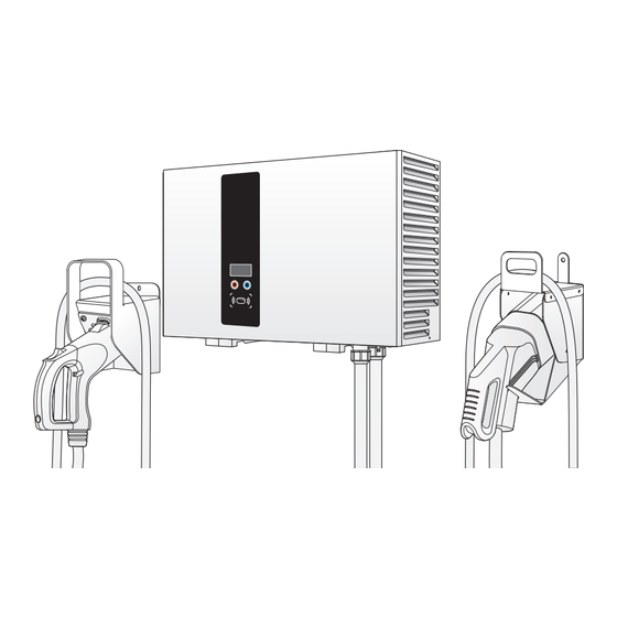
Introduction Applications Public and private parking areas Community parking areas Parking areas of hotels, supermarkets and shopping malls Workplace parking areas Charging stations Highway rest areas Key switch 3G antenna Emergency CCS2 button Charging plug and cable CHAdeMO Charging plug... -
Seite 7: Important Safety And Wiring Instructions
Important Safety and Wiring Instructions Important Safety and Wiring Instructions Installation Site Selection DC Wallbox can be installed in both indoor and outdoor environments. It is necessary to consider the installation conditions and protection at the site: Follow local electrical regulation and installation standards ... -
Seite 8: Service Wiring
Important Safety and Wiring Instructions Service Wiring Ground Connection Always connect the Neutral at the service to Earth Ground. If ground is not provided by the electrical service, a grounding stake must be installed nearby. The grounding stake must be connected to the ground bar in the main breaker panel, and the Neutral must be connected to Ground at that point. - Seite 9 200V - 230V Three-Phase WARNING! The following diagram illustrates the DC Wallbox connection to L1, L2, and L3 in a Delta- connection power grid feed. The earth ground must be connected to neutral at a single point, typically at the breaker panel. WARNING! An earth connection is essential before connecting supply.
-
Seite 10: Before Installation
Before Installation Before Installation Safety Requirements Be sure to preview the standard operating procedures (SOP) and ensure local building and elec- trical codes are reviewed before installing the DC Wallbox charger. The DC Wallbox charger should be installed by a qualified technician according to the instruction ... -
Seite 11: Recommended Tools
Before Installation Recommended Tools The following tools are recommended for the DC Wallbox charger installation: (1x) Voltmeter or digital multi-meter (1x) Water level (1x) Hammer (1x) Concrete drilling machine (1x) Wire cutters/strippers ® (1x) Torx Tamper-Resistant T15 and T25 screwdriver ... -
Seite 12: Installing The Dc Wallbox Charger
Installing the DC Wallbox Charger Installing the DC Wallbox Charger Preparation 1. Release the screws on the crate (two sides) with a No. 8 socket wrench. 2. Open top lid of plywood crate. 3. Take out mounting template and cut off the cable ties to move the charging plug. Installation and Operation Manual... -
Seite 13: Wall Mounting
Installing the DC Wallbox Charger 4. Remove top foam, open plastic bag and take out the unit. Note: Carefully place the unit and the charging plug on the ground or a flat surface at this stage. Wall Mounting 1. Use template and leveler tool to mark out the mounting position. 4 0 0 m 2 3 0 m m 2. - Seite 14 Installing the DC Wallbox Charger WARNING! To ensure adequate ventilation and maintenance space, leave a minimum of 45 cm (18 inches) on both sides of the charger. 3. Place unit onto bracket. Align the back chassis of unit with the corresponding slot on the bracket. Slowly slide down the unit until it sits firmly on the bracket.
-
Seite 15: Making The Connection
Making the Connection Making the Connection WARNING! Only use a Torx® Tamper-Resistant T15 screwdriver to secure or remove the screws. Use of any other tool may damage screws and panel. Power Wiring 1. Open front cover for wiring. a. Release two screws on top. b. - Seite 16 Making the Connection CAUTION! FED WIRING MAY CAUSE THE RISK OF WATER LEAKAGE O NOT CHOOSE THIS WIRING CONNECTION IN OUTDOOR LOCATIONS 3. Fasten cable gland to secure wires. Note: To insure protection from the elements, make sure to use certified IP55 (or above) cable glands.
- Seite 17 Making the Connection Connect the ground wire of RNB14-6 into the earth terminal marked with ground symbol ) using 1 x M6.0 screw with 20 kg-cm Torque force. Wiring the 200Vac - 230Vac L1 L2 L3 Use conduit hub and conduit size M50 according to EN 61386-24. ...
-
Seite 18: Ethernet Connection
Making the Connection 7. Put front cover back and fasten screws securely. Ethernet Connection It is recommended to connect Ethernet cables through the underside access ports. It is necessary to open front cover. 1. Remove the water proof cap from the Ethernet access port. 2. - Seite 19 Making the Connection 3G Connection 1. Remove right filter cover. a. Release the screws on the top. b. Release the screws on the bottom and pull out the latch. c. Open and remove the filter cover. WARNING! ® Only use a Torx Tamper-Resistant T25 screwdriver to secure or remove the screws of unit.
- Seite 20 Making the Connection 3. Insert micro SIM card onto 3G board. Fasten the protection cover back. 4. Return right filter cover. a. Hang filter cover onto the unit. b. Pull down the pin and place back filter cover. c. Fasten screws on bottom. d.
- Seite 21 Making the Connection e. Close the latch at the bottom. The latch has a hole of 3.3mm in diameter to put a padlock into it to avoid tampering. Set Charging Plug 1. Mount charging plug hanger onto the wall. 2. Place charging cable and plug on the hanger properly. IEC DC (CCS2) CHAdeMO - only for dual output model 3.
-
Seite 22: Operation
Operation Operation 1. Choose the preferred language. 2. Choose a compatible plug (CCS or CHAdeMO). CHAdeMO CCS2 CARD 3. Connect the plug to the EV. 4. Swipe the authorized RFID card to start charging. The authorized RFID can be use directly without any activation or setting. - Seite 23 Operation 5. Once charging commences, status information is displayed on the screen. The following illustra- tions demonstrate the start to near complete charging procedure. Status CARD 6. Swipe the authorized RFID card to stop. 7. Return the plug to the holder. Installation and Operation Manual...
-
Seite 24: System Configuration
System Configuration System Configuration WARNING! Only configure the charger when the charger is not in charging mode to avoid interruption of an ongoing charging session. Steps: 1. Contact service provider to login online configuration tool. 2. When the configuration is done, copy the parameter file (DeltaDCWallboxConfig) to the root of a USB flash drive (the drive format should be FAT/FAT32, <... -
Seite 25: Firmware Update
System Configuration Request APN information from the operator and make sure APN is configured correctly via the configu- ration tool. Firmware Update Firmware updates can be made via the USB port on the bottom of the cabinet. 1. Obtain a USB flash drive. The drive format should be FAT/FAT32, < 32GB. 2. -
Seite 26: Maintenance
Warranty General warranty requirements Delta warrants that the products will be free from defects in materials and workmanship for a period of two years for EVSE from the S/N stamped on the product by the original purchaser from Delta Com- pany. -
Seite 27: System Code
System Code System Code Alarm Code Description 004001 System input voltage is higher than workable range (> 305 volt) 004002 System input voltage (L2 or L3) is lower than workable range (< 170 volt) 004003 System output voltage is higher than EV battery maximum voltage 004004 Request output current from EV is higher than present EVSE ability 004005... - Seite 28 System Code Alarm Code Description 00500E 3G module is not ready (module itself or SIM) 00500F WiFi module is not ready 006001 3G connection is disconnected from APN 006002 3G connection is disconnected from internet 006003 3G connection is disconnected from backend office 006008 Ethernet connection is disconnected from internet 006009...
- Seite 29 System Code Alarm Code Description 008016 The temperature of 12 volt for EV communication is higher than workable range 008017 The temperature of 5 volt for other system modules is higher than workable range 008018 The temperature of 24 volt for relay control is higher than workable range 008019 The ambinet temperature of aux.
-
Seite 30: Troubleshooting
1. Confirm the configuration setting. Authentication mode should be by Delta Card. 2. Use another Delta Card to retry. If the new card is successful. You should replace the other RFID card. What should I do if I press the emergency button by accident. (Alarm code: 00400A) ... -
Seite 31: Specifications
Specifications Specifications Model EVDE25XXDXX EVDE25XXEXX Input rating 380-415 Vac; 50/60Hz; 50A max. 200-230 Vac; 50/60Hz; 90A max. Wiring 3-phase/L1, L2, L3, N, PE 3-phase/L1, L2, L3, PE Power factor > 0.98 Current THD Compliant with EN61000-3-12, IEEE 519 Efficiency 94% at nominal output power DC output #1 IEC CCS DC Level 2, 50-500 Vdc, 60A max., 25kW max. - Seite 33 DC Wallbox Chargeur Manuel d’installation et d’utilisation Version: 1.2.0 Date d'émission: 2020/03...
- Seite 34 ABLE DES ATIÈRES Introduction ..........1 Caractéristiques .
-
Seite 35: Conventions Typographiques
Conventions Conventions générales Les conventions suivantes sont utilisées dans ce manuel: Remarque: Indique des informations supplémentaires pertinentes par rapport au processus ou à la procédure en cours. AVERTISSEMENT! Le signal d'avertissement figure avant le texte auquel il se rapporte, afin de souligner que ce texte peut éviter des dommages à... - Seite 36 écrite de Delta. Comme l'élaboration et l'amélioration du produit se poursuivront de manière permanente, Delta pourra modifier ce manuel et le mettre à jour de temps en temps, sans avis préalable. Delta fera de son mieux pour tenir ce Manuel à jour et maintenir l'exactitude de ses informations.
-
Seite 37: Introduction
Introduction Introduction La borne de charge DC Wallbox est actuellement la meilleure option pour alimenter les véhicules élec- triques à batterie (VEB) et les véhicules électriques hybrides rechargeables (VHR). Elle est conçue pour réaliser une charge rapide aussi bien à des emplacements publics que privés, comme les aires de stationnement des magasins de détail et les parkings commerciaux, les stations de charge de flotte, les aires de service des autoroutes, les lieux de travail, les lieux d'habitation, etc. -
Seite 38: Applications
Introduction Applications Aires de stationnement publiques et privées Aires de stationnement de communautés Parkings d'hôtels, de supermarchés et de centres commerciaux Parkings de lieux de travail Stations de charge Aires de repos des autoroutes Interrupteur à... -
Seite 39: Importantes Instructions De Sécurité Et De Câblage
Importantes instructions de sécurité et de câblage Importantes instructions de sécurité et de câblage Sélection du site d'installation DC Wallbox peut être installé dans des environnements intérieurs et extérieurs. Il est nécessaire de prendre en compte les conditions et la protection d'installation sur le site : Respecter les réglementations électriques et les normes d'installation locales ... -
Seite 40: Câblage De Service
Importantes instructions de sécurité et de câblage Câblage de service Mise à la terre Raccordez toujours à la terre le neutre du service. Si l'installation électrique est dépourvue de connex- ion de terre, un piquet de terre devra être installé à proximité. Le piquet de terre doit être raccordé à la barre de terre du tableau électrique principal, et le neutre doit être mis à... - Seite 41 Importantes instructions de sécurité et de câblage 200 V - 230 V triphasé AVERTISSEMENT! Cette alimentation provient d'un réseau électrique à montage en triangle, et la borne DC Wallbox peut être connectée à L1, L2 ou L3, et au neutre. Le neutre ne doit être relié à la terre qu'en un seul point, normalement au tableau des disjoncteurs.
-
Seite 42: Avant L'installation
Avant l'installation Avant l'installation Exigences de sécurité Avant d'installer la borne de charge DC Wallbox, veillez à prévoir les procédures opératoires normalisées (PON) et à vérifier les règlements locaux sur la construction et l'électricité. La borne de charge DC Wallbox doit être installée par un technicien qualifié, conformément aux ... -
Seite 43: Outils Conseillés
Avant l'installation Outils conseillés Les outils suivants sont conseillés pour l'installation de la borne de charge DC Wallbox : 1 voltmètre ou un multimètre numérique 1 niveau à bulle 1 marteau 1 perceuse pour béton 1 pince à couper et dénuder les fils électriques ... -
Seite 44: Installation De La Borne De Charge Dc Wallbox
Installation de la borne de charge DC Wallbox Installation de la borne de charge DC Wallbox Préparation 1. Desserrez les vis de la caisse à claire-voie (des deux côtés) avec une clé à douille No 8. 2. Ouvrez le couvercle supérieur de la caisse ajourée en contreplaqué. 3. -
Seite 45: Montage Mural
Installation de la borne de charge DC Wallbox 4. Enlevez la mousse du dessus, ouvrez le sac en plastique et sortez l'appareilunit. Remarque: Pour le moment, posez avec précaution l'appareil et le connecteur de charge par terre ou sur une surface plane. Montage mural 1. - Seite 46 Installation de la borne de charge DC Wallbox 3. Placez l'appareil sur le support. Alignez le châssis du dos de l'appareil sur la fente correspon- dante du support. Laissez descendre doucement l'appareil jusqu'à ce qu'il soit fermement appuyé sur le support. Serrez les deux vis par en dessous. Remarque: Les vis de fixation inférieures se trouvent dans la trousse d'accessoires.
-
Seite 47: Réalisation De La Connexion
Réalisation de la connexion Réalisation de la connexion AVERTISSEMENT! Pour sécuriser ou retirer les vis, utilisez uniquement un tournevis Torx® inviolable T15. L'utilisation de tout autre outil pourrait endommager les vis et le panneau. Câblage de l'alimentation 1. Pour câbler, ouvrez le panneau avant. a. - Seite 48 Réalisation de la connexion 3. Serrez les presse-étoupe pour fixer les câbles. Remarque: Pour la protection des passe-câbles contre les intempéries, utilisez des presse-étoupe certifiés IP55 ou supérieurs. 4. Enlevez le couvercle du bornier et branchez les fils sur les bornes correctes. Voyez les informa- tions qui suivent sur les connexions de modèles spécifiques.
- Seite 49 Réalisation de la connexion Câblage des fils 200-230 V CA L1 L2 L3 Utilisez une entrée de conduite et des conduites de taille M50 conformes EN 61386-24. Branchez les trois câbles d'alimentation à cosses à anneau avec œillets de câbles ...
-
Seite 50: Connexion Ethernet
Réalisation de la connexion 7. Remetttez en place le panneau avant et resserrez fermement les vis. Connexion Ethernet Il est recommandé de brancher les câbles Ethernet aux ports d'accès du dessous. Pour ce faire, il faut ouvrir le panneau avant. 1. - Seite 51 Réalisation de la connexion Connexion 3G 1. Enlevez le couvercle du filtre de droite. a. Retirez les vis du dessus. b. Libérez les vis du dessous et tirez sur le loquet pour le libérer. c. Ouvrez et enlevez le couvercle du filtre. AVERTISSEMENT! ®...
- Seite 52 Réalisation de la connexion 3. Insérez la carte micro SIM dans la carte 3G. Remettez et resserrez le panneau de protection. 4. Remettez le couvercle du filtre de droite. a. Suspendez le couvercle du filtre sur l'appareil. b. Tirez la goupille vers le bas et remettez en place le couvercle du filtre. c.
- Seite 53 Réalisation de la connexion e. Fermez le verrou en bas. Le verrou dispose d’un trou de 3,3 mm de diamètre afin d’y insérer un cadenas pour éviter toute altération. Installation de la prise de charge 1. Fixez au mur le support de suspension de la prise de charge. 2.
-
Seite 54: Utilisation
Utilisation Utilisation 1. Choisissez votre langue préférée. 2. Choisissez une prise compatible (CCS ou CHAdeMO). CHAdeMO CCS2 CARD 3. Branchez la prise sur le VE. 4. Passez la carte RFID autorisée pour commencer la charge. La RFID autorisée peut être utilisée directement sans aucune activation ou réglage. - Seite 55 Utilisation 5. Dès que la charge commence, les infos sur le statut s'affichent à l'écran. Les illustrations suiva- ntes montrent la procédure de charge du début jusqu'à près de la fin. Statut CARD Charge en kilowatts-heures (kWh) Temps restant jusqu'à la pleine charge (h:m:s) Niveau de charge de la batterie (%) Temps écoulé...
-
Seite 56: Configuration Du Système
Configuration du système Configuration du système AVERTISSEMENT! Ne configurez la borne de charge que si elle n'est pas en mode de charge, afin d'éviter d'interrompre une charge en cours. Étapes: 1. Contactez le fournisseur de services pour vous connecter à l'outil de configuration en ligne. 2. -
Seite 57: Configuration 3G
Configuration du système Configuration 3G Pour les modèles équipés d'un modem 3G, insérez une carte SIM 3G (WCDMA) valide comme expli- qué à des étapes précédentes (page 15) afin de démarrer la connexion 3G. Consultez l'opérateur local pour activer d'abord le service de données sur la carte SIM. Désactivez le contrôle par code PIN dans la carte SIM avant d'insérer celle-ci dans le modem. -
Seite 58: Maintenance
Delta garantit que les produits seront exempts de défauts de matériaux et de fabrication pendant une période de deux ans pour EVSE à partir du S / N estampillé sur le produit par l'acheteur initial de Delta Company. Cette garantie s’applique uniquement à l’acheteur initial et n’est pas transférable à un tiers. -
Seite 59: Code Système
Code système Code système Code Description d'alarme 004001 La tension d'entrée au système est supérieure à la plage de travail (> 305 volts) La tension d'entrée au système (L2 ou L3) est inférieure à la plage de travail 004002 (< 170 volts) La tension de sortie du système est supérieure à... - Seite 60 Code système Code Description d'alarme 005005 La communication avec le VE CCS est perdue 005006 Le redresseur d'alimentation est cassé (SMR) 005007 La communication avec le contrôleur CCS est perdue 005008 La communication avec le module d'alimentation auxiliaire est perdue 005009 La communication avec le module de contrôle des relais est perdue 00500C...
- Seite 61 Code système Code Description d'alarme 00800D Les 12 volts pour les communications du VE sont hors plage vers le bas 00800E Les 24 volts pour le contrôle des relais sont hors plage vers le bas L'intensité de sortie des 5 volts pour le contrôleur du système est hors plage vers le 008010 haut Le courant de sortie des 5 volts pour d'autres modules du système est hors plage...
- Seite 62 Code système Code Description d'alarme 00B006 La mise à jour du microprogramme du module de conversion de puissance a échoué 00C001 Le module PLC pour la charge CCS est cassé 00C002 La proximité CCS est déconnectée 00C003 Arrêt de la charge par le VE CCS 00D001 Pas de permission de charge provenant du VE CHAdeMO 00D002...
-
Seite 63: Dépannage
1. Confirmez les paramètres de configuration. Le mode d'authentification doit être réalisé par Delta Card. 2. Réessayez avec une autre carte Delta. Si celle-ci est appropriée. Vous devez remplacer l'autre carte RFID. Que dois-je faire si j'appuie sur le bouton d'urgence par erreur. (Code d’alarme : 00400A) ... -
Seite 64: Caractéristiques
Caractéristiques Caractéristiques Modèle EVDE25XXDXX EVDE25XXEXX 380-415 V CA ; 50/60 Hz ; 200-230 V CA ; 50/60 Hz ; Entrée nominale 50 A max. 90 A max. Câblage Triphasé / L1, L2, L3, N, PE Triphasé / L1, L2, L3, PE Facteur de puissance >... - Seite 65 DC Wallbox-Ladegerät Installations- und Bedienungshandbuch Version: 1.2.0 Ausgabedatum: 2020/03...
- Seite 66 NHALTSVERZEICHNIS Einführung..........1 Merkmale .
-
Seite 67: Typografische Konventionen
Konventionen Allgemeine Konventionen In diesem Handbuch werden die folgenden Konventionen verwendet: Hinweis: Verweist auf zusätzliche relevanten Informationen zu einem aktuellen Prozess oder Verfahren. WARNUNG! Warnhinweise vor dem Text verweisen auf Informationen zur Vermeidung von Geräte- oder Ausrüstungsschäden. VORSICHT! NGABEN ZU VORSICHTIGEN VERHALTENSWEISEN WERDEN DEM TEXT VORANGESTELLT ORSICHTSHINWEISE IN GROSSBUCHSTABEN VERWEISEN AUF WICHTIGE GESUNDHEITS SICHERHEITSINFORMATIONEN Typografische Konventionen... - Seite 68 Das Eigentum sowie die geistigen Eigentumsrechte an diesem Installations- und Bedienungshandbuch (dieses „Handbuch“), insbesondere die darin enthaltenen Inhalte, Daten und Abbildungen, sind das Eigentum von Delta Electronics, Inc. („Delta“). Das Handbuch ist ausschließlich für den Betrieb oder die Verwendung des Produktes bestimmt. Die Weitergabe, Vervielfältigung, Verbreitung, Reproduktion, Modifizierung, Übersetzung, Extrahierung oder anderweitige Nutzung des Handbuchs ist ohne die vor-...
-
Seite 69: Einführung
Einführung Einführung Das DC Wallbox-Ladegerät ist aktuell erste Wahl für die Aufladung von batterieelektrische Fahrzeugen (BEV) und elektrischen Plug-in-Fahrzeugen (PHEV). Es wurde für die Schnellaufladung an öffentlichen und privaten Orten entwickelt, beispielsweise Einzelhandels-und Gewerbeparkplätze, Flottenladesta- tionen, Autobahn-Tankstellen, Arbeitsplätze, Wohngebäude usw. Der Vorteil des DC Wallbox-Ladegeräts ist die einfache Installation. -
Seite 70: Anwendungen
Einführung Anwendungen Öffentliche und private Parkflächen Gemeinschaftsparkplätze Parkplätze von Hotels, Supermärkten und Einkaufszentren Parkplätze am Arbeitsplatz Ladestationen Autobahn-Rastplätze Schlüsselsch alter Antenne Notfalltaste CCS2 Ladestecker und -kabel CHAdeMO Ladestecker und -kabel 2,7-Zoll-OLED Drucktasten RFID-Kartenlesegerat CARD Installations- und Bedienungshandbuch... -
Seite 71: Wichtige Sicherheits- Und Verkabelungshinweise
Wichtige Sicherheits- und Verkabelungshinweise Wichtige Sicherheits- und Verkabelungshinweise Auswahl des Installationsstandorts DC Wallbox kann sowohl im Innen- als auch im Außenbereich installiert werden. Es ist nötig, die Gege- benheiten und Sicherheitsvorkehrungen der Installation am Standort zu berücksichtigen: Befolgen Sie die örtlichen Vorschriften und Vorgaben für elektrische Installationen ... -
Seite 72: Verdrahtung
Abbildung 1. 380 V bis 415 V dreiphasiger Anschluss 200 V bis 230 V dreiphasige Spannung WARNUNG! Zuleitung ab einem Delta-Stromnetz zu DC Wallbox zu L1, L2 und L3 und Nullleiter. Die Erdung wird nur an einem Punkt mit dem Nullleiter verbunden, im Allgemeinen am Hauptschalter. -
Seite 73: Vor Der Installation
Vor der Installation Vor der Installation Schutz Ziehen Sie vor der Montage des DC Wallbox-Ladegeräts die Standardbetriebsverfahren (SOP) und die geltenden Gebäude- und VDE-Vorschriften heran. Die Installation des DC Wallbox-Ladegerätes muss einem qualifizierten Techniker vorbehalten sein. Bei der Verbindung des Netzstromkabels sind entsprechende Schutzmaßnahmen vorzusehen. ... -
Seite 74: Empfohlene Werkzeuge
Vor der Installation Empfohlene Werkzeuge Die folgenden Werkzeuge werden für die Montage des DC Wallbox-Ladegerätes empfohlen: (1x) Spannungsmesser oder digitales Multimeter (1x) Wasserwaage (1x) Hammer (1x) Betonbohrmaschine (1x) Drahtschneider/Abisolierzange ® (1x) Torx Manipulationssicher T15 und T25 Schraubendreher ... -
Seite 75: Montage Des Dc Wallbox-Ladegeräts
Montage des DC Wallbox-Ladegeräts Montage des DC Wallbox-Ladegeräts Preparation 1. Die Schrauben an der Kiste (beidseitig) mit einem Schraubendreher Nr. 8 lösen. 2. Obere Abdeckung der Sperrholzkiste öffnen. 3. Montageschablone herausnehmen, die Kabelbinder durchschneiden und den Ladestecker her- ausnehmen. Installations- und Bedienungshandbuch... -
Seite 76: Wandhalterung
Montage des DC Wallbox-Ladegeräts 4. Schaumstoff herausnehmen, Plastikbeutel öffnen und die Einheit herausnehmen. Hinweis: Das Gerät und den Ladestecker nun auf dem Boden oder auf einer flachen Oberfläche abstellen. Wandhalterung 1. Die Montageposition mithilfe der Schablone und einer Wasserwaage markieren. 4 0 0 m 2 3 0 m m 2. - Seite 77 Montage des DC Wallbox-Ladegeräts 3. Gerät auf die Halterung setzen. Die Hinterseite des Gerätes im entsprechenden Schlitz in der Halterung ausrichten. Die Hinterseite des Gerätes im entsprechenden Schlitz in der Halterung ausrichten. Am Boden mit zwei Schrauben befestigen. Hinweis: Diese Befestigungsschrauben liegen dem Zubehörset bei. Installations- und Bedienungshandbuch...
-
Seite 78: Verbindungsherstellung
Verbindungsherstellung Verbindungsherstellung WARNUNG! Die Schrauben nur mit einem manipulationssicheren Torx®-T15-Schraubendreher befestigen und lösen. Andere Werkzeuge können Schrauben und Blech beschädigen. Leistungsverdrahtung 1. Vordere Abdeckung für die Verdrahtung öffnen. a. Am Boden mit zwei Schrauben befestigen. b. Die Laschen lösen, um die vordere Abdeckung zu öffnen. c. - Seite 79 Verbindungsherstellung 3. Kabel mit der Kabelmuffe sichern. Hinweis: Zum Schutz vor Witterungseinflüssen ausschließlich zugelassene Kabelmuffen verwenden, mindestens IP55 (bzw. darüber). 4. Den Deckel von der Klemmleiste entfernen und die Drähte mit den richtigen Klemmen verbin- den. Modellspezifische Anschlüsse entnehmen Sie bitte den nachstehenden Angaben. Die Verkabelung/Verdrahtung ist abhängig vom Modell und von einphasigen und dreiphasigen Modellen.
- Seite 80 Verbindungsherstellung Verkabelung mit 200 VAC - 230 VAC L1 L2 L3 Es sind ein Anschlussstück und ein Anschluss M50 gemäß EN 61386-24 zu wählen. Die Stromkabel der 3 x RNB38-6-Ringklemmen mit Kabelösen an der Eingangsklemme „L1, L2 und L3“ mit 3-x-M6.0-Schrauben mit 33 kg-cm Anzugsmoment befestigen. Den Erdungsdraht von RNB14-6 mit der 1-x-M6.0 Schrauben mit 20 kg-cm Anzugsmom- ...
-
Seite 81: Ethernet-Verbindung
Verbindungsherstellung Ethernet-Verbindung Es wird empfohlen, die Ethernet-Kabel durch die Anschlüsse an der Unterseite zu führen. Dazu muss die vordere Abdeckung geöffnet werden. 1. Die Wasserschutzkappe vom Ethernet-Anschluss abnehmen. 2. Das Kabel durch die Öffnung führen und dann das Ethernet-Kabel mit der Klemme verbinden. 3. -
Seite 82: Anschluss
Verbindungsherstellung 3G-Anschluss 1. Die rechte Filterabdeckung abnehmen. a. Die Schrauben an der Oberseite lösen. b. Die Schrauben an der Unterseite lösen und die Lasche herausziehen. c. Die Filterabdeckung öffnen und herausnehmen. WARNUNG! ® Die Schrauben nur mit einem manipulationssicheren Torx T25-Schraubendreher befestigen und lösen. - Seite 83 Verbindungsherstellung 3. Die Mikro-SD-Karte in die 3G-Platine einsetzen. Die Schutzabdeckung wieder befestigen. 4. Die rechte Filterabdeckung wieder anbringen. a. Die Filterabdeckung auf die Einheit hängen. b. Den Stift nach unten ziehen und die Filterabdeckung einsetzen. c. Am Boden mit den Schrauben befestigen. d.
- Seite 84 Verbindungsherstellung Ladestecker befestigen 1. Die Aufhängung für den Ladestecker an der Wand befestigen. 2. Das Ladekabel und den Stecker richtig in der Aufhängung befestigen. CHAdeMO - nur für das Modell mit doppeltem IEC DC (CCS2) Ausgang 3. Strom einschalten und den Schlüssel drehen, um DC Wallbox nach Abschluss aller Schritte zu initialisieren.
-
Seite 85: Bedienung
Bedienung Bedienung 1. Wählen Sie die gewünschte Sprache. 2. Wählen Sie einen kompatiblen Stecker (CCS oder CHAdeMO). CHAdeMO CCS2 CARD 3. Den Stecker mit der EV verbinden. 4. Die autorisierte RFID-Karte durchziehen, um den Ladevorgang zu beginnen. Die autorisierte RFID kann direkt und ohne jegliche Aktivierung oder Einstellung verwendet werden. Installations- und Bedienungshandbuch... - Seite 86 Bedienung 5. Sobald die Aufladung beginnt, werden die Statusinformationen am Display angezeigt. Die nachstehen- den Abbildungen demontieren die Sequenz vom Start bis zum nahezu abgeschlossenen Ladevorgang. Status CARD Aufladung in Kilowatt-Stunden (kWh) Verbleibende Zeit bis zur vollständigen Aufladung (h:m:s) Batterieaufladung (%) Dauer (h:m:s) 6.
-
Seite 87: Systemkonfiguration
Systemkonfiguration Systemkonfiguration WARNUNG! Das Ladegerät darf niemals während des laufenden Lademodus aufgeladen werden, weil sonst die laufende Ladesitzung unterbrochen wird. Schritte: 1. Das vom DC Wallbox-Hersteller herausgegebene Windows-basierte Konfigurationstool verwen- den. 2. Nach Abschluss der Konfiguration kopieren Sie die Parameterdatei (DeltaDCWallboxConfig) auf ein USB-Flash-Laufwerk (Dateiformat: FAT/FAT32). -
Seite 88: 3G-Konfiguration
Systemkonfiguration 3G-Konfiguration Bei Modellen mit 3G-Modem legen Sie eine gültige 3G (WCDMA) SIM-Karte (siehe vorhergehende Schritte (Seite 14)), um die 3G-Verbindung herzustellen. Informieren Sie sich bitte vorab bei Ihrem lokalen Betreiber hinsichtlich von Datendiensten auf der SIM-Karte. Deaktivieren Sie die PIN-Überprü- fung der SIM-Karte bevor Sie die Karte in das Modem einführen. -
Seite 89: Wartung
Gewährleistung Allgemeine Gewährleistungsbedingungen Delta gewährleistet, dass das Produkt während eines Zeitraums von zwei (2) Jahren frei von Verarbeit- ungs- und Materialfehlern ist, für den Originalkäufer des Produktes von Delta Company, d.h. mit auf EVSE aufgestempelter S/N-Nummer. Diese Gewährleistung richtet sich nur an den Originalkäufer und sie ist nicht an Dritte übertragbar. -
Seite 90: Systemcode
Systemcode Systemcode Alarmcode Beschreibung 004001 System-Eingangsspannung überschreitet den Betriebsbereich (> 305 Volt) System-Eingangsspannung (L2 oder L3) unterschreitet den Betriebsbereich (> 170 004002 Volt) 004003 System-Ausgangsspannung überschreitet die max. EV-Batteriespannung 004004 Angeforderter Ausgangsstrom von EV überschreitet die aktuelle EVSE-Leistung Die Temperatur am Lufteintritt oder Eingangsschütz überschreitet den 004005 Betriebsbereich (<60°C) Die Temperatur am Lufteintritt oder Eingangsschütz überschreitet den... - Seite 91 Systemcode Alarmcode Beschreibung 005007 CCS Controller-Kommunikation unterbrochen 005008 Hilfsstrommodul Kommunikation unterbrochen 005009 Relaissteuermodul Kommunikation unterbrochen 00500C Display-Modul Kommunikation unterbrochen 00500D RFID-Modul Kommunikation unterbrochen 00500E 3G-Modul nicht bereit (Modul oder SIM) 00500F WLAN-Modul nicht bereit 006001 3G-Verbindung zu APN getrennt 006002 3G-Verbindung zum Internet getrennt 006003 3G-Verbindung in Backend-Office getrennt...
- Seite 92 Systemcode Alarmcode Beschreibung 008010 5-Volt Ausgangsstrom für System-Controller überschreitet den Betriebsbereich 008011 5-Volt Ausgangsstrom für andere Systemmodule überschreitet den Betriebsbereich 008012 5-Volt Ausgangsstrom für den CAN-Bus überschreitet den Betriebsbereich 008013 12-Volt Ausgangsstrom für andere Systemmodule überschreitet den Betriebsbereich 008014 12-Volt Ausgangsstrom für die EV-Kommunikation überschreitet den Betriebsbereich 008015 24-Volt Ausgangsstrom für die Relaissteuerung überschreitet den Betriebsbereich 008016...
- Seite 93 Systemcode Alarmcode Beschreibung 00D007 Batterie OTP von CHAdeMO EV 00D008 Voreinstellung Ausgangsspannung weicht ab von Zielspannung 00D009 Position Shift-Alarm von CHAdeMO EV 00D00A EV anderer Fehler von CHAdeMO EV 00D00B CHAdeMO Steckerverriegelung defekt Installations- und Bedienungshandbuch...
-
Seite 94: Fehlerbehebung
1. Überprüfen Sie die Konfigurationseinstellungen. Der Authentifizierungsmodus muss mit der Delta Card ausgeführt werden. 2. Versuchen Sie es mit einer anderen Delta Card. Wenn der Versuch mit dieser Karte erfolgreich ist, müssen Sie die andere RFID-Karte austauschen. Was soll ich tun, wenn ich die Alarm-Taste unabsichtlich gedrückt habe. (Alarmcode: 00400A) ... -
Seite 95: Technische Daten
Technische Daten Technische Daten Modell EVDE25XXDXX EVDE25XXEXX Eingangsleistung 380-415 Vac; 50/60Hz; 50A max. 200-230 Vac; 50/60Hz; 90A max. Verkabelung 3-phasig/L1, L2, L3, N, PE 3-phasig/L1, L2, L3, PE Leistungsfaktor > 0,98 Strom Verzerrung Gemäß EN61000-3-12, IEEE 519 Effizienz DC-Ausgang Nr. 1 IEC CCS DC Level 2, 50-500 Vdc, 60A max., 25kW max. - Seite 97 DC Wallbox-laadoplossing Installatie- en bedieningshandleiding Versie: 1.2.0 Uitgiftedatum: 2020/03...
- Seite 98 NHOUDSTAFEL Invoering ..........1 Functionaliteiten .
-
Seite 99: Typografische Conventies
Conventies Algemene conventies De volgende conventies worden gehanteerd in deze handleiding: Opmerking: Duidt aanvullende informatie aan die relevant is voor het huidige proces of procedure. WAARSCHUWING! Waarschuwing wordt weergegeven voor de tekst waarnaar het verwijst om te benadrukken dat de inhoud schade kan voorkomen aan het apparaat of apparatuur. LET OP! ET OP WORDT WEERGEGEVEN VOOR DE TEKST WAARNAAR HET VERWIJST ET OP WORDT... - Seite 100 Handleiding van tijd tot tijd aanpassen of bijwerken zonder kennisgeving. Delta doet zijn best om de Handleiding actueel en juist te houden. Delta wijst elke vorm van garantie of verbintenis af, zowel nad- rukkelijk als impliciet, waaronder, maar niet beperkt tot de volledigheid, juistheid, niet-inbreuk, verkoop- baarheid of geschiktheid voor een bepaald doel of gebruik.
-
Seite 101: Invoering
Invoering Invoering De DC Wallbox-laadoplossing is de beste keuze voor het opladen van elektrische voertuigen op accu en voor alle elektrische plug-in-voertuigen. Hij is ontworpen voor snelladen op zowel particuliere als openbare plekken, denk hierbij aan gemeenschappelijke parkeergarages, algemene oplaadpunten, tankstations, privégarages, etc. -
Seite 102: Toepassingen
Invoering Toepassingen Openbare of particuliere parkeergelegenheid Gemeenschappelijke parkeergelegenheid Parkeergelegenheid bij hotels, supermarkten en winkelcentra Parkeergelegenheid bij kantoor Laadstations Tankstations Sleutelschak elaar Antenne Noodknop CCS2- laadstekker en laadkabel CHAdeMO- laadstekker en laadkabel 2.7” OLED-scherm Druktoetsen RFID-kaartlezer CARD Installatie- en bedieningshandleiding... -
Seite 103: Belangrijke Veiligheids- En Bedradingsinstructies
Belangrijke veiligheids- en bedradingsinstructies Belangrijke veiligheids- en bedradingsinstructies Kiezen van installatielocatie DC Wallbox kan zowel binnen als buiten geïnstalleerd worden. Het is belangrijk om de installatieom- standigheden en veiligheid op de locatie in overweging te nemen: Ga te werk conform lokale elektrische wetgeving en installatiestandaarden ... - Seite 104 Belangrijke veiligheids- en bedradingsinstructies 380V - 415V Driefase WAARSCHUWING! Deze feed is afkomstig van een electriciteitsnet met y-verbinding, en de DC Wallbox kan worden aangesloten op L1, L2 of L3 en nul. Aarding moet direct aangesloten zijn op neutraal op een enkel punt, normaal gesproken bij het schakelpaneel. WAARSCHUWING! Aarding is noodzakelijk voor het aansluiten van een voeding.
-
Seite 105: Voor Installatie
Voor installatie Voor installatie Veiligheidseisen Zorg dat de standaardpraktijkvoorschriften worden bestudeerd en dat lokale bouwvoorschriften en voorschriften rondom elektra worden gevolgd vóór installatie van de DC Wallbox-laadoplossing. De DC Wallbox-laadoplossing dient geïnstaleerd te worden door een erkend electricien, con- ... -
Seite 106: Aanbevolen Gereedschap
Voor installatie Aanbevolen gereedschap Het volgende gereedschap wordt aangeraden bij de installatie van de DC Wallbox-laadoplossing. (1) Spanningsmeter/voltmeter (1) Waterpas (1) Hamer (1) Betonboor (1) Draadsnijder/-stripper ® (1) Torx Tamper-Resistant T15 en T25 schroevendraaier (1) Nr. -
Seite 107: Installatie Van De Dc Wallbox-Laadoplossing
Installatie van de DC Wallbox-laadoplossing Installatie van de DC Wallbox-laadoplossing Voorbereiding 1. Maak de schroeven op het krat (aan twee kanten) los met een nr. 8-moersleutel. 2. Open de bovenkant van de triplex krat. 3. Haal de bevestigingsplaat eruit en snijd de kabelbanden los om de laadstekker te verplaatsen. Installatie- en bedieningshandleiding... -
Seite 108: Muurbevestiging
Installatie van de DC Wallbox-laadoplossing 4. Verwijder het schuim aan de bovenkant, open de plastic zak en haal de unit eruit. Opmerking: Plaats de unit en de laadstekker voorzichtig op de grond of een vlakke ondergrond. Muurbevestiging 1. Gebruik template en waterpas om de bevestigingsplaats te bepalen. 4 0 0 m 2 3 0 m m 2. - Seite 109 Installatie van de DC Wallbox-laadoplossing 3. Plaats de unit op de steun. Zorg dat het achterstel van de unit op één lijn wordt geplaatst met de corresponderende uitsparing in de steun. Schuif de unit langzaam naar beneden totdat deze stevig op de steun rust. Maak vast met twee schroeven aan de onderkant. Opmerking: De onderste schroeven zitten in de accessoireset.
-
Seite 110: Verbinding Maken
Verbinding maken Verbinding maken WAARSCHUWING! ® Maak enkel gebruik van een Torx Tamper-Resistant T15-schroevendraaier om schroeven vast te zetten of te verwijderen. Gebruik van ander gereedschap kan schroeven en paneel beschadigen. Bedrading 1. Open de voorkant voor bedrading. a. Maak twee schroeven aan de bovenkant los. b. - Seite 111 Verbinding maken 3. Bevestig kabelwartel om draden vast te zetten. Opmerking: Maak gebruik van gecertificeerde IP55 (of hoger) voor bescherming tegen weersinvloeden. 4. Verwijder klepje van klemmenblok en verbind de bedrading via de juiste terminals. Bekijk de vol- gende informatie voor verbindingen van specifieke modellen. Bedradingsvereisten zijn afhankelijk van het modeltype en eenfase- en driefase-modellen.
- Seite 112 Verbinding maken Bedrading van de 200Vac - 230Vac L1 L2 L3 Gebruik kabelgoot en -leiding van M50-formaat conform EN 61386-24. Verbind de stroomkabels van 3 x RNB14-6 kabelschoenen met de ingangsaansluiting die gemarkeerd is met ‘L1’, ‘L2’ en ‘L3’ door gebruik te maken van 3 x M6.0 schroeven met 33 kg-cm Torque-kracht. Verbind de aarddraad van RNB14-6 in de aardingsklem die is gemarkeerd met aardingssym- ...
- Seite 113 Verbinding maken Ethernet-verbinding Het is aan te raden om de Ethernet-kabels door de toegangspoorten aan de onderkant te trekken. Het is noodzakelijk om de voorkant open te maken. 1. Verwijder het waterdichte kapje van de Ethernet-toegangspoort. 2. Trek de kabel door de poort en verbind de Ethernet-kabel met de terminal. 3.
- Seite 114 Verbinding maken 3G-verbinding 1. Verwijder de filterafdekking aan de rechterkant. a. Maak de schroeven aan de bovenkant los. b. Maak de schroeven aan de onderkant los en trek de grendel los. c. Open en verwijder de filterafdekking. WAARSCHUWING! ® Maak enkel gebruik van een Torx Tamper-Resistant T25-schroevendraaier om schroeven vast te zetten of te verwijderen.
- Seite 115 Verbinding maken 3. Steek de micro-simkaart in de 3G-opening. 4. Plaats de filterafdekking terug. a. Plaats de filterafdekking op de unit. b. Druk het pinnetje omlaag en plaats de filterafdekking terug. c. Maak schroeven aan de onderkant vast. d. Maak schroeven aan de bovenkant vast. Installatie- en bedieningshandleiding...
- Seite 116 Verbinding maken e. Sluit de grendel aan de onderkant. De grendel heeft een gat met een diameter van 3,3 mm voor het plaatsen van een hangslot ter voorkoming van sabotage. Stel de laadstekker in 1. Zet de laadstekker in de houder aan de muur 2.
-
Seite 117: Bediening
Bediening Bediening 1. Kies voorkeurstaal. 2. Kies een passende stekker (CCS of CHAdeMO) CHAdeMO CCS2 CARD 3. Sluit de stekker aan op het elektrische voertuig 4. Swipe de geautoriseerde RFID-card om te beginnen met laden. De geautoriseerde RFID kan direct worden gebruikt zonder enige activering of instelling. Installatie- en bedieningshandleiding... - Seite 118 Bediening 5. Zodra het laden begint, wordt statusinformatie getoond op het scherm. De volgende tekeningen laten de laadprocedure zien van start tot bijna volledig. Status CARD 6. Swipe de geautoriseerde RFID-card om te stoppen. 7. Swipe de geautoriseerde RFID-card om te stoppen. Installatie- en bedieningshandleiding...
-
Seite 119: Systeemconfiguratie
Systeemconfiguratie Systeemconfiguratie WAARSCHUWING! Configureer de lader alleen als deze niet in laadmodus staat om te voorkomen dat een lopende laadsessie wordt onderbroken. Stappen 1. Neem contact op met serviceprovider om in te loggen bij de online configuratietool. 2. Als de configuratie is afgerond, kopieer dan het parameter-bestand (DeltaDCWallboxConfig) naar de hoofdmap van een USB-flashdrive (geformatteerd als FAT/FAT32, <32GB). -
Seite 120: 3G-Configuratie
Systeemconfiguratie 3G-configuratie Bij modellen met een 3G-modem steekt u een geldige 3G (WCDMA)-simkaart in, zoals uitgelegd in de vorige stappen (pagina 14) om de 3G-verbinding te starten. Zorg vooraf dat de dataservice op de simkaart is geac- tiveerd. Schakel controle met pincode op de simkaart uit voordat deze in de modem wordt gestoken. Vraag APN-gegevens aan bij de provider en zorg dat APN juist is geconfigureerd via de configuratietool. -
Seite 121: Onderhoud
Delta garandeert dat de producten vrij zijn van materiaal- en fabricagefouten voor een periode van twee jaar voor EVSE op basis van de S/N die door de oorspronkelijke koper van Delta Company op het prod- uct is gestempeld. Deze garantie geldt alleen voor de oorspronkelijke koper en is niet overdraagbaar aan een derde partij. -
Seite 122: Systeemcode
Systeemcode Systeemcode Alarmcode Omschrijving 004001 Invoerspanning van het systeem is hoger dan het werkbare bereik (> 305 volt) 004002 Invoerspanning van het systeem is lager dan het werkbare bereik (< 170 volt) 004003 Uitvoerspanning van het systeem is hoger dan het maximale voltage van de EV-accu 004004 Benodigde uitvoerspanning van EV is hoger dan huidige kunnen EVSE 004005... - Seite 123 Systeemcode Alarmcode Omschrijving 00500C Communicatie met display-module werkt niet 00500D Communicatie met RFID-module werkt niet 00500E 3G-module is nog niet gereed (module zelf of sim) 00500F Wifi-module is nog niet gereed 006001 3G-verbinding is niet verbonden met APN 006002 3G-verbinding is niet verbonden met internet 006003 3G-verbinding is niet verbonden met backend-office 006008...
- Seite 124 Systeemcode Alarmcode Omschrijving 008015 De uitgangsstroom van 24 volt voor relaiscontrole is hoger dan toegestaan 008016 De temperatuur van 12 volt voor EV-communictie is hoger dan toegestaan 008017 De temperatuur van 5 volt voor andere systeem-modules is hoger dan toegestaan 008018 De temperatuur van 24 volt voor relaiscontrole is hoger dan toegestaan 008019...
-
Seite 125: Probleemoplossing
1. Bevestig de configuratie-instelling. De authenticatiemodus moet met de Delta Card worden ingesteld. 2. Gebruik een andere Delta Card om opnieuw te proberen. Als het met de nieuwe kaart wel lukt moet de andere RFID-kaart vervangen. Wat moet ik doen als ik per ongeluk op de noodknop druk (alarmcode: 00400A)? ... -
Seite 126: Specificaties
Specificaties Specificaties Model EVDE25XXDXX EVDE25XXEXX Aansluitspanning 380-415 Vac; 50/60Hz; 50A max. 200-230 Vac; 50/60Hz; 90A max. Bedrading Driefase/L1, L2, L3, N, PE Driefase/L1, L2, L3, PE Vermogensfactor > 0,98 Huidig THD In overeenstemming met EN61000-3-12, IEEE 519 Efficiëntie 94% bij nominaal vermogen DC output nr. - Seite 127 Caricabatterie DC Wallbox Manuale di installazione e di utilizzo Versione: 1.2.0 Data di emissione: 2020/03...
- Seite 128 NDICE Introduzione ..........1 Caratteristiche .
-
Seite 129: Convenzioni Tipografiche
Convenzioni Convenzioni generali In questo manuale, vengono utilizzate le seguenti convenzioni: Note: Segnala informazioni aggiuntive, pertinenti al processo o alla procedura in corso. AVVERTENZA! Le informazioni di avvertenza appaiono prima del testo, per sottolineare che il contenuto può aiutare a prevenire danni al dispositivo o all'apparecchiatura. ATTENZIONE! LI AVVISI DI ATTENZIONE APPAIONO PRIMA DEL TESTO A CUI SI RIFERISCONO ONO SCRITTI IN... - Seite 130 (questo "Manuale"), inclusi, ma non solo, i contenuti, i dati e le cifre qui contenuti, sono di proprietà di Delta Electronics, Inc. ("Delta"). Il manuale può essere utilizzato solo per il funzionamento o per l'uso del prodotto. È vietata qualsiasi disposizione, duplicazione, diffusione, riproduzione, modifica, traduzi- one, estrazione o qualsiasi altro utilizzo del manuale senza previa autorizzazione scritta di Delta.
-
Seite 131: Introduzione
Introduzione Introduzione Il caricabatterie DC Wallbox è la scelta migliore per alimentare veicoli elettrici a batteria (BEV) e veicoli elettrici plug-in (PHEV). È progettato per la ricarica rapida in luoghi pubblici e privati, come i parcheggi di attività commerciali, stazioni di ricarica per le flotte, aree di servizio autostradali, luoghi di lavoro, res- idenze, ecc. -
Seite 132: Applicazioni
Introduzione Applicazioni Aree di parcheggio pubbliche e private Aree di parcheggio comuni Parcheggi di hotel, supermercati e centri commerciali Aree di parcheggio sul posto di lavoro Stazioni di ricarica Aree di sosta autostradali Interruttore a chiave ANTENNA Pulsante di... -
Seite 133: Importanti Istruzioni Di Sicurezza E Cablaggio
Importanti istruzioni di sicurezza e cablaggio Importanti istruzioni di sicurezza e cablaggio Selezione del sito di installazione DC Wallbox può essere installato sia in ambienti interni che esterni. È necessario considerare le con- dizioni di installazione e la protezione sul sito: Seguire le normative elettriche locali e gli standard di installazione ... - Seite 134 AVVERTENZA! Lo schema seguente illustra la connessione di DC Wallbox a L1, L2 e L3 a una rete elettrica con connessione Delta. La messa a terra deve essere collegata al neutro in un singolo punto, in genere nel pannello dell'interruttore.
-
Seite 135: Prima Dell'installazione
Prima dell'installazione Prima dell'installazione Norme di sicurezza Assicurati di prendere visione preventivamente delle procedure operative standard (SOP) e assicu- rati di esaminare i codici locali di costruzione ed elettricità di installare il caricatore DC Wallbox. Il caricatore DC Wallbox deve essere installato da un tecnico qualificato in base al manuale di ... -
Seite 136: Strumenti Raccomandati
Prima dell'installazione Strumenti raccomandati I seguenti strumenti sono consigliati per l'installazione del caricatore DC Wallbox: (1x) Voltimetro o multimetro digitale (1x) Livella (1x) Martello (1x) Trapano per cemento (1x) Tronchesi / spelacavi ® (1x) Cacciavite Torx T15 e T25 resistente alle manomissioni ... -
Seite 137: Installazione Del Caricatore Per Dc Wallbox
Installazione del caricatore per DC Wallbox Installazione del caricatore per DC Wallbox Preparazione 1. Svitare le viti sulla cassa (due lati) con una chiave a bussola n. 8. 2. Aprire il coperchio superiore della cassa in compensato. 3. Estrarre la mascherina di montaggio e tagliare le fascette per spostare la spina di ricarica. Manuale di installazione e di utilizzo... -
Seite 138: Montaggio A Parete
Installazione del caricatore per DC Wallbox 4. Rimuovere la schiuma superiore, aprire la busta di plastica ed estrarre l'unità. Note: Collocare con cura l'unità e la spina di ricarica a terra o su una superficie piana in questa fase. Montaggio a parete 1. - Seite 139 Installazione del caricatore per DC Wallbox AVVERTENZA! Per garantire un adeguato spazio di ventilazione e manutenzione, lasciare un minimo di 45 cm (18 pollici) su entrambi i lati del caricatore. 3. Collocare l'unità sulla staffa. Allineare il telaio posteriore dell'unità con lo slot corrispondente sulla staffa.
-
Seite 140: Effettuare La Connessione
Effettuare la connessione Effettuare la connessione AVVERTENZA! ® Usare solo un cacciavite Torx Resistente alle manomissioni T15 per fissare o rimuovere le viti. L'uso di qualsiasi altro strumento può danneggiare viti e pannello. Cablaggio di alimentazione 1. Aprire la protezione anteriore per il cablaggio. a. - Seite 141 Effettuare la connessione 3. Fissare il pressacavo per fissare i cavi. Note: Per assicurare la protezione dagli elementi, assicurarsi di utilizzare pressacavi con certificato IP55 (o superiore). 4. Rimuovere il coperchio della morsettiera e collegare il cablaggio ai terminali corretti. Vedere le seguenti informazioni per le connessioni specifiche al modello.
- Seite 142 Effettuare la connessione Cablaggio del 200Vac - 230Vac L1 L2 L3 Utilizzare il mozzo del condotto e condotto di di dimensione M50 secondo EN 61386-24. Collegare i fili di alimentazione di 3 morsetti ad anello RNBB14-6 con capicorda ai morsetti di ...
- Seite 143 Effettuare la connessione Connessione Ethernet Si consiglia di collegare i cavi Ethernet attraverso le porte di accesso inferiore. È necessario aprire il coperchio anteriore. 1. Rimuovere la protezione impermeabile dalla porta di accesso Ethernet. 2. Inserire il cavo attraverso la porta e collegare il cavo Ethernet al terminale. 3.
- Seite 144 Effettuare la connessione Connessione 1. Rimuovere il coperchio del filtro destro. a. Svitare le viti in alto. b. Svitare le viti sul fondo ed estrarre il fermo. c. Rimuovere il coperchio del filtro. AVVERTENZA! ® Usare solo un cacciavite Torx Resistente alle manomissioni T25 per fissare o rimuovere le viti.
- Seite 145 Effettuare la connessione 3. Inserire la scheda micro SIM nella scheda 3G. Riavvitare il coperchio di protezione. 4. Rimettere il coperchio del filtro destro. a. Appendere il coperchio del filtro sull'unità. b. Tirare verso il basso il perno e posizionare il coperchio del filtro posteriore. c.
- Seite 146 Effettuare la connessione e. Chiudere la serratura a scatto nella parte inferiore. La serratura a scatto ha un foro di 3,3 mm di diametro per inserire un lucchetto al fine di evitare eventuali manomissioni. Montaggio della spina di ricarica 1. Montare il gancio per la spina di ricarica sulla parete. 2.
-
Seite 147: Funzionamento
Funzionamento Funzionamento 1. Scegliere la lingua preferita. 2. Scegli una spina compatibile (CCS o CHAdeMO). CHAdeMO CCS2 CARD 3. Collegare la spina all'EV. 4. Passare la scheda RFID autorizzata per avviare la ricarica. La RFID autorizzata può essere uti- lizzata direttamente senza alcuna attivazione o impostazione. Manuale di installazione e di utilizzo... - Seite 148 Funzionamento 5. Una volta iniziata la ricarica, le informazioni sullo stato vengono visualizzate sullo schermo. Le seguenti illustrazioni mostrano l’ inizio della procedura di ricarica fino al quasi completamento. Condizione CARD 6. Scorrere la scheda RFID autorizzata per interrompere. 7. ricollocare la spina sul supporto. Manuale di installazione e di utilizzo...
-
Seite 149: Configurazione Del Sistema
Configurazione del sistema Configurazione del sistema AVVERTENZA! Configurare il caricabatterie solo quando non è in modalità di ricarica per evitare l'interruzione di una sessione di ricarica in corso. Passaggi: 1. Contattare il fornitore di servizi per accedere allo strumento di configurazione online. 2. -
Seite 150: Configurazione
Configurazione del sistema Configurazione Per i modelli dotati del modem 3G, inserire una carta SIM 3G (WCDMA) valida come descritto nei pas- saggi precedenti (pagina 14) per avviare la connessione 3G. Consultare l'operatore locale per attivare preventivamente il servizio dati sulla scheda SIM. Disabilitare il controllo PIN sulla carta SIM prima di inserire la scheda nel modem. -
Seite 151: Manutenzione
Garanzia Requisiti generali di garanzia Delta garantisce che i prodotti sono esenti da difetti di materiale e di lavorazione per un periodo di due anni per EVSE dal Numero di Serie impresso sul prodotto dall'acquirente originale della Società Delta. Questa garanzia si applica solo all'acquirente originale e non è trasferibile a terzi. -
Seite 152: Codice Del Sistema
Codice del sistema Codice del sistema Codice Descrizione allarme 004001 La tensione di ingresso del sistema è superiore al limite di funzionamento (> 305 volt) La tensione di ingresso del sistema (L2 o L3) è inferiore al limite di funzionamento 004002 (<... - Seite 153 Codice del sistema Codice Descrizione allarme 005007 La comunicazione con il controller CCS è interrotta 005008 La comunicazione con il modulo di alimentazione ausiliaria è interrotta 005009 La comunicazione con il modulo di controllo del relè è interrotta 00500C La comunicazione con il modulo del display è interrotta 00500D La comunicazione con il modulo RFID è...
- Seite 154 Codice del sistema Codice Descrizione allarme 00800D 12 volt per la comunicazione EV è inferiore all’intervallo di operazione 00800E 24 volt per il controllo del relè è inferiore all’intervallo di operazione La corrente di uscita di 5 volt per il controller di sistema è superiore all’intervallo di 008010 operazione La corrente di uscita di 5 volt per altri moduli di sistema è...
- Seite 155 Codice del sistema Codice Descrizione allarme 00B006 L'aggiornamento del firmware del modulo convertitore di potenza è fallito 00C001 Il modulo PLC per la carica CCS è guasto 00C002 La prossimità CCS è disconnessa 00C003 Interrompere la ricarica con CCS EV 00D001 Autorizzazione di carica negata da EV CHAdeMO 00D002...
-
Seite 156: Guida Alla Risoluzione Dei Problemi
1. Confermare l'impostazione della configurazione. La modalità di autenticazione dovrebbe essere tramite Delta Card. 2. Utilizzare un'altra Carta Delta per riprovare. Se l’operazione con la nuova carta va a buon fine. Si dovrebbe procedere alla sostituzione dell'altra scheda RFID. Cosa devo fare se premo il pulsante di emergenza per sbaglio. (Codice di allarme: 00400A) ... -
Seite 157: Specifiche
Specifiche Specifiche Modello EVDE25XXDXX EVDE25XXEXX Ingresso nominale 380-415 Vac; 50/60Hz; 50A max. 200-230 Vac; 50/60Hz; 90A max. Cablaggio 3 fasi / L1, L2, L3, N, PE 3 fasi / L1, L2, L3, PE Fattore di potenza > 0,98 Corrente THD Conforme a EN61000-3-12, IEEE 519 Efficienza 94% alla potenza di uscita nominale... - Seite 159 DC Wallbox Lader Installasjonshåndbok og bruksanvisning Versjon: 1.2.0 Utstedelsesdato: 2020/03...
- Seite 160 NNHOLDSFORTEGNELSE Innledning ..........1 Funksjoner .
- Seite 161 Konvensjoner Generelle konvensjoner De følgende konvensjonene brukes i denne bruksanvisningen: Merk: Indikerer ytterligere informasjon som er relevant for den nåværende prosessen eller prosedyren. ADVARSEL! Informasjon om advarsel vises før den aktuelle teksten for å fremheve at innholdet kan forhindre skade på enheten eller utstyret. OBS! ARSLER VISES FØR DEN AKTUELLE TEKSTEN ARSLER VISES MED STORE BOKSTAVER FOR Å...
- Seite 162 Delta. Ettersom produktet blir kontinuerlig utviklet og forbedret, kan Delta endre eller oppdatere bruksanvisningen av og til uten varsel. Delta kommer til å gjøre sitt beste for å holde bruksanvisningen oppdatert og opprettholde nøyaktigheten til bruksanvisnin- gen.
-
Seite 163: Innledning
Innledning Innledning DC Wallbox-laderen er det beste valget for å drive elbiler med batteri og ladbare hybridbiler på marke- det i dag. Den er designet for rask lading på både offentlige og private steder, for eksempel parkering- splasser utenfor butikker, flåteladestasjoner, serviceområder langs hovedveier, arbeidsplasser, boliger, osv. -
Seite 164: Bruksområder
Innledning Bruksområder Offentlige og private parkeringsområder Kommunale parkeringsområder Parkeringsområder for hoteller, supermarkeder og handlesenter Parkeringsområder på arbeidssteder Ladestasjoner Rasteplasser langs hovedveier Nøkkelbryter Antenne Nødknapp CCS2 Ladeplugg og - kabel CHAdeMO Ladeplugg og - kabel 2,7"... -
Seite 165: Viktige Sikkerhets- Og Kablingsinstruksjoner
Viktige sikkerhets- og kablingsinstruksjoner Viktige sikkerhets- og kablingsinstruksjoner Valg av installasjonssted DC Wallbox kan installeres både utendørs og innendørs. Det er viktig å vurdere installasjonsforholdene og sikkerheten på stedet: Følg lokale elektrisitetsforskrifter og installasjonsstandarder Ta hensyn til nødutgangene og rømningsveiene på installasjonsstedet ... -
Seite 166: Servicekabling
Figur 1. 380-415 V trefaset ledningsforbindelse 200-230 V trefaset ADVARSEL! Denne innmatingen er fra et strømnett med Delta-kopling, og DC Wallbox kan kobles til L1, L2 eller L3 og til nulleder. Jord må være koblet til nullederen på bare ett punkt, vanligvis på bryterpanelet. - Seite 167 Før montering Før montering Sikkerhetskrav Sørg for at du gjennomgår standard driftsprosedyre (SOP) og sikrer at lokale bygge- og elek- trisitetsforskrifter er gjennomgått før montering av DC Wallbox-laderen. DC Wallbox-laderen skal monteres av en kvalifisert tekniker i henhold til bruksveiledningen og ...
-
Seite 168: Før Montering
Før montering Anbefalte verktøy Følgende verktøy anbefales for montering av DC Wallbox-laderen: (1x) Voltmeter eller digitalt universalmåleverktøy (1x) Vannvater (1x) Hammer (1x) Boremaskin for betong (1x) Avbiter/avisoleringstang ® (1x) Torx inngrepssikker T15- og T25-skrujern (1x) Nr. -
Seite 169: Montering Av Dc Wallbox-Laderen
Montering av DC Wallbox-laderen Montering av DC Wallbox-laderen Forberedelse 1. Løsne skruene på kassen (to sider) med en nr. 8 pipenøkkel. 2. Åpne topplokket til finerplatekassen. 3. Ta ut monteringsmalen og kutt av kabelstroppene for å bevege ladepluggen. Installasjonshåndbok og bruksanvisning... - Seite 170 Montering av DC Wallbox-laderen 4. Fjern skumplasten øverst, åpne plastposen og ta ut enheten. Merk: Plasser enheten og ladepluggen på bakken eller en flat overflate på dette punktet. Veggmontering 1. Bruk malen og nivelleringsverktøyet til å markere monteringsposisjonen. 4 0 0 m 2 3 0 m m 2.
- Seite 171 Montering av DC Wallbox-laderen 3. Plasser enheten i braketten. Rett inn den bakre innsatsrammen til enheten med samsvarende spor på braketten. Dra enheten sakte nedover til den sitter godt på braketten. Fest to skruer nedenfra. Merk: Festeskruene for underdelen finnes i tilbehørssettet. Installasjonshåndbok og bruksanvisning...
-
Seite 172: Utføre Tilkoblingen
Utføre tilkoblingen Utføre tilkoblingen ADVARSEL! Bruk bare et Torx® inngrepssikker T15-skrujern til å fjerne skruene. Bruk av andre verktøy kan skade skruene og panelet. Tilkobling av strøm 1. Åpne frontdekselet for kabling. a. Løsne to skruer øverst. b. Løsne låsene for å åpne frontdekselet. c. - Seite 173 Utføre tilkoblingen 3. Fest kabelgjennomføringen for å sikre ledninger. Merk: For å sikre beskyttelse mot vær og vind må du sørge for å bruke sertifiserte IP55- kabelgjennomføringer (eller over). 4. Fjern lokket på kabelhodet og koble ledningene til riktige terminaler. Se følgende informasjon for tilkobling for spesifikke modeller.
- Seite 174 Utføre tilkoblingen Kabling av 200-230 VAC L1 L2 L3 Bruk ledningsnavn og ledningsstørrelse M50 i henhold til EN 61386-24. Koble strømledningene til 3 x RNB38-6-ringterminal med kabelsko til inngangsterminalen merket med L1 , L2 og L3 med 3 x M6.0-skruer med 33 kg-cm momentkraft. Koble jordledningen til RNB14-6 innn i jordterminalen merket med jordsymbolet ( ) med ...
- Seite 175 Utføre tilkoblingen Ethernet-tilkobling Det anbefales å koble Ethernet-kabler via tilgangsportene på undersiden. Det er nødvendig å åpne frontdekselet. 1. Fjern det vanntette dekselet fra Ethernet-tilgangsporten. 2. Sett kabelen inn gjennom porten og koble Ethernet-kabelen til terminalen. 3. Fest ledningen eller kabelfjennomføringen for å feste kabelen. Merk: For å...
- Seite 176 Utføre tilkoblingen 3G-tilkobling 1. Fjern det høyre filterdekselet. a. Løsne skruene øverst. b. Løsne skruene nederst og trekk ut låsen. c. Åpne og fjern filterdekselet. ADVARSEL! ® Bruk bare et Torx inngrepssikker T25-skrujern til å fjerne skruene på enheten. Bruk av andre verktøy kan skade skruene og panelet.
- Seite 177 Utføre tilkoblingen 3. Sett inn mikro-SIM-kort på 3G-panelet. Fest beskyttelsesdekselet igjen. 4. Sett det høyre filterdekselet på plass. a. Heng filterdekselet på enheten. b. Trekk ned pluggen og sett filterdekselet på plass. c. Fest skruer nederst. d. Fest skruer øverst. Installasjonshåndbok og bruksanvisning...
- Seite 178 Utføre tilkoblingen e. Lukk klinken på bunnen. Klinken har et hull på 3,3 mm i diameter hvor du kan sette inn en hengelås for å unngå tukling. Sett ladeplugg 1. Monter hengeren for ladepluggen på veggen. 2. Plasser ladekabelen og -pluggen på riktig måte på hengeren. IEC DC (CCS2) CHAdeMO - bare for modell med dobbel utgang 3.
-
Seite 179: Bruk
Bruk Bruk 1. Velg foretrukket språk. 2. Velg en kompatibel plugg (CCS eller CHAdeMO). CHAdeMO CCS2 CARD 3. Koble pluggen til elbilen. 4. Sveip et autorisert RFID-kort for å starte lading. Den autoriserte RFID-en kan brukes direkte uten aktivering eller innstilling. Installasjonshåndbok og bruksanvisning... - Seite 180 Bruk 5. Når ladingen starter, vises statusinformasjon på skjermen. De følgende illustrasjonene demon- strerer starten til nesten fullført ladeprosedyre. Status CARD Ladning i kilowatt-timer (kWh) Gjenværende tid til full ladning (t:m:s) Batteriets ladetilstand (%) Nåværende varighet (t:m:s) 6. Sveip det autoriserte RFID-kortet for å stoppe. 7.
-
Seite 181: Konfigurasjon Av Systemet
Konfigurasjon av systemet Konfigurasjon av systemet ADVARSEL! Bare konfigurer laderen når laderen ikke er i lademodus, for å unngå avbrudd av en pågående ladeøkt. Trinn: 1. Bruk det Windows-baserte konfigurasjonsverktøyet fra DC Wallbox-produsenten. 2. Når konfigurasjonen er ferdig, kopierer du parameterfilen (DeltaDCWallboxConfig) til roten til en USB-minnepinne (filformatet skal være FAT/FAT32). -
Seite 182: 3G-Konfigurasjon
Konfigurasjon av systemet 3G-konfigurasjon For modeller som er utstyrt med 3G-modemet, setter du inn et gyldig 3G-SIM-kort (WCDMA) i henhold til instruksjonene i tidligere trinn (side 14) for å starte 3G-tilkoblingen. Konsulter den lokale operatøren for å aktivere datatjeneste på SIM-kortet på forhånd. Deaktiver sjekk av PIN-kode på SIM-kortet før du setter kortet inn i modemet. -
Seite 183: Vedlikehold
Garanti Generelle garantikrav Delta garanterer at produktene vil være uten feil i materialer og arbeid i en periode på to år for EVSE fra S/N stemplet på produktet, av den originale kjøperen fra Delta Company. Denne garantien gjelder kun den originale kjøperen og kan ikke overføres til en tredjepart. -
Seite 184: Systemkode
Systemkode Systemkode Alarmkode Beskrivelse 004001 Systemets inngangsspenning er høyere enn gjennomførbart spekter (> 305 volt) Systemets inngangsspenning (L2 eller L3) er lavere enn gjennomførbart spekter 004002 (< 170 volt) Systemets utgangsspenning er høyere enn den maksimale spenningen for batteriet 004003 på... - Seite 185 Systemkode Alarmkode Beskrivelse 005007 Kommunikasjon med CCS-kontroller er brutt 005008 Kommunikasjon med hjelpemodul for strøm er ødelagt 005009 Kommunikasjon med modul for reléstyring er ødelagt 00500C Kommunikasjon med visningsmodul er ødelagt 00500D Kommunikasjon med RFID-modulen er brutt 00500E 3G-modul er ikke klar (selve modulen eller SIM-kort) 00500F Wi-Fi-modulen er ikke klar 006001...
- Seite 186 Systemkode Alarmkode Beskrivelse Utgangsspenningen på 5 volt for systemkontroller er høyere enn gjennomførbart 008010 spekter Utgangsspenningen på 5 volt for andre systemmoduler er høyere enn 008011 gjennomførbart spekter 008012 Utgangsspenningen på 5 volt for CAN-buss er høyere enn gjennomførbart spekter Utgangsspenningen på...
- Seite 187 Systemkode Alarmkode Beskrivelse 00C002 CCS-nærhet er frakoblet 00C003 stopp lading av CCS EV 00D001 Ingen ladetillatelse kommer fra CHAdeMO EV 00D002 Batterifeil kommer fra CHAdeMO EV 00D003 Batteriet er inkompatibelt med CHAdeMO EV 00D006 Nåværende utgangsstrøm er forskjellig fra målstrøm 00D007 Batteri-OTP kommer fra CHAdeMO EV 00D008...
-
Seite 188: Feilsøking
1. Bekreft konfigurasjonsinnstillingen. Bekreftelsesmodus bør være av Delta Card. 2. Bruk et annet Delta Card for å prøve igjen. Hvis det nye kortet lykkes. Du bør erstatte det andre RFID-kortet. Hva gjør jeg hvis jeg trykker på nødknappen ved et uhell? (Alarmkode: 00400A) ... -
Seite 189: Spesifikasjoner
Spesifikasjoner Spesifikasjoner Modell EVDE25XXDXX EVDE25XXEXX Inngangsverdi 380-415 VAC; 50/60Hz; 50 A maks. 200-230 VAC; 50/60Hz; 90 A maks. Kabling Trefaset/L1, L2, L3, N, PE Trefaset/L1, L2, L3, PE Effektfaktor > 0,98 Nåværende THD Overholder EN61000-3-12, IEEE 519 Effektivitet DC-utgang 1 IEC CCS DC-nivå... - Seite 191 Carregador DC Wallbox Instalação e Manual de Instruções Versão: 1.2.0 Data de emissão: 2020/03...
- Seite 192 Í NDICE Introdução ..........1 Caraterísticas .
-
Seite 193: Convenções Tipográficas
Convenções Convenções Gerais Neste manual são utilizadas as seguintes convenções: Nota: Indica informações adicionais importantes para o atual processo ou procedimento. ALERTA! As informações de alerta surgem antes do texto a que se referem para enfatizar que o conteúdo pode prevenir danos ao dispositivo ou ao equipamento. PERIGO! S AVISOS DE PERIGO SURGEM ANTES DO TEXTO A QUE SE REFEREM S AVISOS DE PERIGO... - Seite 194 Qualquer distribuição, duplicação, disseminação, reprodução, modificação, tradução, extração, ou outra utilização do Manual sem a obtenção de permissão escrita prévia da Delta é proibida. Uma vez que o produto será continuamente desenvolvido e melhorado, a Delta pode modi- ficar ou atualizar periodicamente o Manual sem qualquer aviso.
-
Seite 195: Introdução
Introdução Introdução Atualmente, o carregador DC Wallbox é a melhor escolha para alimentar veículos elétricos movidos a bateria (BEV, do inglês "Battery Electric Vehicle) e veículos elétricos híbridos projetados para também poderem ser recarregados através de uma fonte de energia elétrica externa (PHEV, do inglês "Plug-In Hybrid Electric Vehicle"). -
Seite 196: Aplicações
Introdução Aplicações Espaços de estacionamento públicos e privados Espaços de estacionamento comunitários Áreas de estacionamento de hotéis, supermercados e centros comerciais Áreas de estacionamento de locais de trabalho Estações de carregamento Áreas de descanso de autoestradas ... -
Seite 197: Instruções Importantes A Nível De Segurança E Instalação Da Cablagem
Instruções Importantes a Nível de Segurança e In- Instruções Importantes a Nível de Segurança e Instalação da Cablagem Seleção do Local de Instalação O carregador DC Wallbox pode ser instalado em espaços interiores ou exteriores. É necessário levar em conta as condições de instalação e proteção no local: Cumpra os regulamentos e normas de instalação locais referentes a sistemas elétricos ... - Seite 198 O diagrama seguinte ilustra a ligação do carregador DC Wallbox ao terminais L1, L2 e L3 num circuito de alimentação a partir da rede elétrica com uma ligação delta. A ligação do neutro à terra tem de ser estabelecida apenas num ponto, sendo geralmente feita no painel de disjuntores.
-
Seite 199: Antes Da Instalação
Antes da Instalação Antes da Instalação Requisitos de Segurança Antes de instalar o carregador Wallbox DC, certifique-se de consultar os procedimentos operacionais normalizados (PON) e analisar os códigos de construção e de instalação de sistemas elétricos locais. A instalação do carregador DC Wallbox tem de ser feita por um técnico qualificado de acordo ... -
Seite 200: Ferramentas Recomendadas
Antes da Instalação Ferramentas Recomendadas Para instalar o carregador DC Wallbox, recomenda-se a utilização das seguintes ferramentas: (1 x) Voltímetro ou multímetro digital (1 x) Nível de bolha de ar (1 x) Martelo (1 x) Martelo pneumático ... -
Seite 201: Instalação Do Carregador Dc Wallbox
Instalação do Carregador DC Wallbox Instalação do Carregador DC Wallbox Preparação 1. Solte os parafusos da caixa (dois lados) com uma chave de caixa n.º 8. 2. Abra a tampa superior da caixa de contraplacado. 3. Tire o modelo de montagem e corte as amarras dos cabos para retirar a ficha de carregamento. 4. - Seite 202 Instalação do Carregador DC Wallbox Nota: Com cuidado, coloque o aparelho e o carregador no chão ou sobre uma superfície plana. Wall Mounting 1. Utilize o modelo e a ferramenta niveladora para marcar a posição de montagem. 4 0 0 m 2 3 0 m m 2.
- Seite 203 Instalação do Carregador DC Wallbox 3. Coloque a unidade no suporte. Alinhe a estrutura traseira da unidade com o orifício de encaixe correspondente do suporte. Lentamente, faça deslizar a unidade, até que assente com firmeza no suporte. Aperte os dois parafusos da parte inferior. Nota: Os parafusos de fixação da parte inferior encontram-se no conjunto de acessórios.
-
Seite 204: Fazer A Ligação
Fazer a Ligação Fazer a Ligação ALERTA! ® Para fixar ou remover os parafusos, utilize exclusivamente uma chave de fendas Torx Tamper-Resistant T15. A utilização de qualquer outra ferramenta poderá danificar os parafusos e o painel. Cablagem Elétrica 1. Abra a tampa dianteira para aceder à cablagem. a. - Seite 205 Fazer a Ligação 3. Aperte o prensa-cabos para fixar os fios. Nota: A fim de garantir a proteção contra intempéries, certifique-se de que utiliza prensa-cabos certificados IP55 (ou superiores). 4. Retire a tampa do módulo de terminais e ligue a cablagem aos terminais corretos. Para saber como fazer as ligações de modelos específicos, consulte as informações seguintes.
- Seite 206 Fazer a Ligação Ligação de 200 VAC - 230 VAC L1 L2 L3 Utilizar boquilha e tubo de tamanho M50, conforme prescrito pela norma EN 61386-24. Ligue os fios elétricos dos 3 terminais de olhal RNB14-6, com terminais de cabo, ao termi- ...
- Seite 207 Fazer a Ligação Ligação à Ethernet Recomenda-se que a ligação do cabo de Ethernet seja feita através dos pontos de acesso que se encontram na parte inferior. É necessário abrir a tampa frontal. 1. Retire a tampa à prova de água da porta Ethernet. 2.
- Seite 208 Fazer a Ligação Ligação 3G 1. Remova a tampa do filtro da direita. a. Solte os parafusos da parte superior. b. Solte os parafusos da parte inferior e puxe a tranca. c. Abra e retire a tampa do filtro. ALERTA! ®...
- Seite 209 Fazer a Ligação 3. Introduza o cartão micro SIM na placa 3G. Volte a fixar a tampa de proteção. 4. Volte a colocar a tampa do filtro da direita. a. Pendure a tampa do filtro na unidade. b. Puxe o pino para baixo e coloque a tampa traseira do filtro. c.
- Seite 210 Fazer a Ligação e. Feche o trinco na parte inferior. O trinco tem um orifício de 3,3mm de diâmetro para colocar nele um cadeado a fim evitar a sua adulteração. Preparação da Ficha de Carregamento 1. Monte o suporte de parede da ficha de carregamento. 2.
-
Seite 211: Funcionamento
Funcionamento Funcionamento 1. Escolha o idioma preferido. 2. Escolha uma ficha compatível (CCS ou CHAdeMO). CHAdeMO CCS2 CARD 3. Ligue a ficha ao EV. 4. Para iniciar o carregamento, faça um gesto de percorrer sobre o cartão RFID autorizado. A RFID autorizada pode ser utilizada diretamente sem qualquer ativação ou definição. - Seite 212 Funcionamento 5. Assim que o carregamento começar, as informações de estado serão apresentadas no ecrã. As ilustrações seguintes demonstram os procedimentos desde o início do carregamento até ao carregamento quase completo. Estado CARD 6. Para interromper o carregamento, faça um gesto de percorrer sobre o cartão RFID autorizado. 7.
-
Seite 213: Configuração Do Sistema
Configuração do Sistema Configuração do Sistema ALERTA! Configure o carregador apenas quando não estiver em modo de carregamento, a fim de evitar interromper uma sessão de carregamento em curso. Passos 1. Para iniciar sessão na ferramenta de configuração online, contacte o fornecedor do serviço. 2. -
Seite 214: Configuração 3G
Configuração do Sistema Configuração 3G Para modelos equipados com o modem 3G, introduza um cartão SIM 3G (WCDMA) válido, conforme detalhado nos passos anteriores (página 14), a fim de iniciar a ligação 3G. Para ativar previamente o serviço de dados no cartão SIM, consulte o operador local. Antes de introduzir o cartão no modem, desative a verificação de PIN no cartão SIM. -
Seite 215: Manutenção
Requisitos gerais de garantia A Delta garante que os produtos estarão isentos de defeitos em material e processo de fabrico durante um período de dois anos para o EVSE a partir do Número de Série gravado no produto pelo comprador original da Delta Company. -
Seite 216: Código De Sistema
Código de Sistema Código de Sistema Código de Descrição Alarme A tensão de entrada do sistema é superior aos limites de funcionamento 004001 recomendados (> 305 volts) A tensão de entrada (L2 ou L3) é inferior aos limites de funcionamento 004002 recomendados (>... - Seite 217 Código de Sistema Código de Descrição Alarme 005001 Avaria nas comunicações com o CHAdeMO EV 005005 Avaria nas comunicações com o CCS EV 005006 Avaria no retificador de potência (SMR) 005007 Avaria nas comunicações com o controlador CCS 005008 Avaria nas comunicações com o módulo de alimentação auxiliar 005009 Avaria nas comunicações com o módulo de controlo de relé...
- Seite 218 Código de Sistema Código de Descrição Alarme O valor de 12 volts para a comunicação com o EV é superior aos limites de 008007 funcionamento recomendados O valor de 24 volts para o controlo de relé é superior aos limites de funcionamento 008008 recomendados O valor de 5 volts para o controlador de sistema é...
- Seite 219 Código de Sistema Código de Descrição Alarme 00A004 Falha de unidade no contactor de entrada 2 00A005 Defeito de solda no polo positivo do relé de saída para carregamento via CCS 00A006 Defeito de unidade no polo positivo do relé de saída para carregamento via CCS 00A007 Defeito de solda no polo positivo do relé...
-
Seite 220: Resolução De Problemas
1. Confirme as definições de configuração. O modo de autenticação deve ser por cartão Delta Card. 2. Utilize outro Delta Card para tentar novamente. Caso do novo cartão seja bem sucedido. Deve substituir o outro cartão RFID. O que devo fazer se premir o botão de emergência acidentalmente. (Código de alarme: 00400A) ... -
Seite 221: Especificações
Especificações Especificações Modelo EVDE25XXDXX EVDE25XXEXX Classificação de 380-415 Vac; 50 / 60Hz; 50A no 200-230 Vac; 50 / 60Hz; 90A no entrada máximo máximo Cablagem Trifásico/L1, L2, L3, N, PE Trifásico/L1, L2, L3, PE Fator de potência > 0,98 DHT da corrente Em conformidade com a norma EN61000-3-12, IEEE 519 Eficiência 94% à... - Seite 223 DC Wallbox Cargador Manual de Instalación y Operación Versión: 1.2.0 Fecha de asunto: 2020/03...
- Seite 224 Í NDICE Introducción..........1 Características .
-
Seite 225: Convenciones Tipográficas
Convenciones Convenciones generales En este manual se utilizan las convenciones siguientes: Nota: Indica información adicional que es relevante para el proceso o procedimiento actual. ¡ADVERTENCIA! La información de advertencia aparece antes del texto al que hace referencia para subrayar que el contenido puede evitar daños al equipo o equipamiento. ¡PRECAUCIÓN! A PRECAUCIÓN APARECE ANTES DEL TEXTO AL QUE HACE REFERENCIA A PRECAUCIÓN... - Seite 226 Delta. Puesto que el producto se desarrolla y mejora de forma continua, Delta puede modificar o actualizar el Manual de vez en cuando sin previo aviso. Delta hará todo lo que esté en su mano para mantener el Manual actualizado, así como la precisión del este Manual.
-
Seite 227: Introducción
Introducción Introducción El cargador de pared de corriente continua DC Wallbox es la mejor elección en la actualidad para ali- mentar vehículos provistos de batería eléctrica (BEV y vehículos eléctricos enchufables (PHEV). Está diseñado para carga rápida en zonas tanto públicos como privados, tales como espacios de estaciona- miento de minoristas y establecimientos comerciales, estaciones de carga de flotas, áreas de des- canso en autopistas, centros de trabajo, residencias, etc. -
Seite 228: Aplicaciones
Introducción Aplicaciones Zonas de estacionamiento públicas y privadas Zonas de aparcamiento comunitario Zonas de aparcamiento hoteles, supermercados y centros comerciales Zonas de aparcamiento en centros de trabajo Estaciones de carga Áreas de descanso en autopistas ... -
Seite 229: Instrucciones De Seguridad Y Conexión Importantes
Instrucciones de seguridad y conexión importantes Instrucciones de seguridad y conexión impor- tantes Selección del lugar de instalación DC Wallbox puede instalarse tanto en interior como en exterior. Es necesario tener en cuenta las condiciones de instalación y protección en el lugar: Siga las normas locales de regulación eléctrica e instalación. - Seite 230 Instrucciones de seguridad y conexión importantes 380 V - 415 V TRIFÁSICA ¡ADVERTENCIA! Esta corriente eléctrica procede de una red eléctrica con conexión bifurcada, y el DC Wallbox puede conectar a L1, L2 o L3, y al neutro. La conexión a tierra debe conectarse al neutro solamente en un punto, normalmente en el panel de disyuntor.
-
Seite 231: Kit De Accesorios
Antes de la instalación Antes de la instalación Requisitos de seguridad Asegúrese de revisar previamente los procedimientos operativos normalizados (SOP) y garantizar que se revisan los códigos eléctricos y de edificación locales antes de instalar el cargador DC Wallbox. Un técnico autorizado deberá... -
Seite 232: Antes De La Instalación
Antes de la instalación Herramientas recomendadas Se recomiendan las siguientes herramientas para instalar el cargador DC Wallbox: (1x) Voltímetro o multímetro digital (1x) Nivel de agua (1x) Martillo (1x) Perforadora de hormigón (1x) Cortacables/tenazas ® (1x) Destornillador Torx de seguridad T15 y T25 ... -
Seite 233: Instalación Del Cargador Dc Wallbox
Instalación del cargador DC Wallbox Instalación del cargador DC Wallbox Preparación 1. Libere los tornillos de la caja (dos lados) con una llave recta de tubo n.º 8. 2. Abra la tapa superior de la caja de madera contrachapada. 3. Extraiga la plantilla de montaje y corte las bridas de cable para mover el enchufe de carga. Manual de Instalación y Operación... -
Seite 234: Montaje En Pared
Instalación del cargador DC Wallbox 4. Retire la espuma de la parte superior, abra la bolsa de plástico y extraiga la unidad. Nota: Con mucho cuidado, coloque la unidad y el enchufe de carga en el suelo o en una superficie plana a nivel. - Seite 235 Instalación del cargador DC Wallbox 3. Coloque la unidad en el soporte. Alinee la parte posterior del bastidor de la unidad con la ranura correspondiente del soporte. Deslice lentamente hacia abajo la unidad hasta que se asiente firmemente en el soporte. Apriete dos tornillos de la parte inferior. Nota: Los tornillos de fijación de la parte inferior se encuentran en el kit de accesorios.
-
Seite 236: Realizar La Conexión
Realizar la conexión Realizar la conexión ¡ADVERTENCIA! Utilice solamente un destornillador Torx® de seguridad T15 para apretar o quitar los tornillos. El uso de cualquier otra herramienta puede dañar los tornillos y el panel. Cableado de la alimentación eléctrica 1. Abra la cubierta frontal del cableado. a. - Seite 237 Realizar la conexión 3. Apriete el prensaestopas para fijar los cables. Nota: Para asegurar la protección de los elementos, asegúrese de usar prensaestopas con certificación IP55 (o superior). 4. Retire la tapa del bloque de terminales y conecte el cableado a los terminales adecuados. Vea la siguiente información para determinar las conexiones específicas del modelo.
- Seite 238 Realizar la conexión Cableado del 200Vac - 230Vac L1 L2 L3 Use el conector terminal y tamaño de conducto M50 según la norma EN 61386-24. Conecte los cables de alimentación de la arandela terminal 3 x RNB38-6 con los termina- ...
-
Seite 239: Conexión Ethernet
Realizar la conexión 7. Vuelva a colocar la cubierta frontal y apriete los tornillos firmemente. Conexión Ethernet Se recomienda conectar los cables Ethernet a través de los puertos de acceso situados en la parte inferior. Es necesario abrir la cubierta frontal. 1. - Seite 240 Realizar la conexión Conexión 3G 1. Retire la cubierta del filtro derecho. a. Suelte los tornillos de la parte superior. b. Suelte los tornillos de la parte inferior y tire del pestillo. c. Abra y retire la cubierta del filtro. ¡ADVERTENCIA! ®...
- Seite 241 Realizar la conexión 3. Introduzca una tarjeta micro SIM en el panel 3G. Vuelva a colocar la cubierta de protección. 4. Devuelva la cubierta del filtro derecho. a. Cuelgue la cubierta del filtro en la unidad. b. Estire de la pestaña y vuelva a colocar la cubierta del filtro. c.
- Seite 242 Realizar la conexión CHAdeMO - solamente para modelos de salida IEC DC (CCS2) doble 3. Conecte el interruptor de encendido y gire la llave para inicializar el DC Wallbox cuando se hayan completado todos los pasos. Manual de Instalación y Operación...
-
Seite 243: Operación
Operación Operación 1. Seleccione el idioma preferido. 2. Seleccione un enchufe compatible (CCS o CHAdeMO). CHAdeMO CCS2 CARD 3. Conecte el enchufe al VE. 4. Pase la tarjeta TF autorizada para iniciar la carga. La RFID autorizada se puede usar directa- mente sin ninguna activación o configuración. - Seite 244 Operación 5. Cuando comience la carga, se mostrará en la pantalla la información de estado. Las siguientes ilustraciones muestran el procedimiento completo, desde el inicio hasta la finalización. Estado CARD Carga en kilovatios-hora (kWh) Tiempo restante para la carga completa (h:m:s) Estado de carga de la batería (%) Duración actual (h:m:s) 6.
-
Seite 245: Configuración Del Sistema
Configuración del sistema Configuración del sistema ¡ADVERTENCIA! Configure el cargador solamente cuando no esté en modo de carga, para no interrupción de una sesión de carga en curso. Pasos: 1. Use la herramienta de configuración compatible con Windows publicada por el fabricante del DC Wallbox. -
Seite 246: Configuración 3G
Configuración del sistema Configuración 3G Para los modelos provistos de módem 3G, introduzca una tarjeta SIM 3 G (WCDMA) como se ha indi- cado en pasos anteriores (página 14) para iniciar la conexión 3G. Pida a su operador local que active el servicio de datos de la tarjeta SIM con antelación. -
Seite 247: Mantenimiento
Requisitos generales de garantía Delta garantiza que los productos estarán libres de defectos de material y mano de obra por un período de dos años para el EVSE con el número de serie estampado en el producto por el comprador original de la empresa Delta. -
Seite 248: Código Del Sistema
Código del sistema Código del sistema Código de Descripción alarma 004001 La tensión de entrada del sistema es mayor que el intervalo de trabajo (> 305 voltios) La tensión de entrada del sistema (L2 o L3) es menor que el intervalo de trabajo 004002 (<... - Seite 249 Código del sistema Código de Descripción alarma 005006 El rectificador de potencia está roto (SMR) 005007 La comunicación con el controlador CCS se ha interrumpido 005008 La comunicación con el módulo de alimentación auxiliar se ha interrumpido 005009 La comunicación con el módulo de control del relé se ha interrumpido 00500C La comunicación con el módulo de pantalla se ha interrumpido 00500D...
- Seite 250 Código del sistema Código de Descripción alarma 00800C 12 voltios para otros módulos del sistema es menor que el intervalo de trabajo 00800D 12 voltios para la comunicación con el VE es menor que el intervalo de trabajo 00800E 24 voltios para control de relé es menor que el intervalo de trabajo La tensión de salida de 5 voltios para el controlador del sistema es mayor que el 008010 intervalo de trabajo...
- Seite 251 Código del sistema Código de Descripción alarma 00B004 La actualización del firmware del módulo para la carga CCS ha fallado 00B005 La actualización del firmware del módulo para la carga CHAdeMO ha fallado 00B006 La actualización del firmware del módulo del convertidor de potencia ha fallado 00C001 El módulo PLC para la carga CCS está...
-
Seite 252: Solución De Problemas
1. Compruebe la configuración. El modo de autenticación debería ser mediante tarjeta Delta. 2. Inténtelo con otra tarjeta Delta. Si la nueva tarjeta funciona, debe reemplazar la otra tarjeta RFID. ¿Qué debo hacer si pulso el botón de emergencia por accidente? (Código de alarma: 00400A) ... -
Seite 253: Especificaciones
Especificaciones Especificaciones Modelo EVDE25XXDXX EVDE25XXEXX Tensión nominal de 380-415 VAC; 50/60 Hz; 50 A máx. 200-230 VAC; 50/60 Hz; 90A máx. entrada Cableado 3-fase/L1, L2, L3, N, PE 3-fase/L1, L2, L3, PE Factor de potencia > 0,98 Corriente THD Cumple la norma EN61000-3-12, IEEE 519 Eficiencia Salida CC n.º... - Seite 255 Stacja ładowania DC Wallbox Podręcznik instalacji i obsługi Wersja: 1.2.0 Data wydania: 2020/03...
- Seite 256 SPIS TREŚCI Wstęp ........... 1 Charakterystyki.
- Seite 257 Oznaczenia Ogólne oznaczenia W niniejszym dokumencie używane są następujące oznaczenia: Uwaga: Przekazuje dodatkowe informacje ważne z punktu widzenia bieżącego procesu lub procedury. OSTRZEŻENIE! Ostrzeżenia umieszczone są przed fragmentem, którego dotyczą, w celu poinformowania o konieczności zapoznania się z ich treścią, co umożliwi uniknąć uszkodzenia urządzenia lub wyposażenia.
-
Seite 258: Prawa Autorskie
Wszelkie przekazywanie, powielanie, rozpowszechnianie, reproduk- cja, zmiana, opracowywanie wyciągów z treści dokumentu oraz jakiekolwiek inne wykorzystanie podręcznika bez uzyskania uprzedniej pisemnej zgody Delta jest zakazane. Biorąc pod uwagę stały rozwój i doskonalenie produktu, Delta zastrzega sobie prawo do wprowadzania modyfikacji i aktual- izacji do niniejszego podręcznika bez uprzedniego powiadomienia. -
Seite 259: Wstęp
Wstęp Wstęp Stacja ładowania DC Wallbox to obecnie wiodący produkt w branży BEV (pojazdy w pełni elektryczne) oraz PHEV (hybrydowe pojazdy elektryczne typu plug-in). Została ona zaprojektowana z myślą o szyb- kim ładowaniu pojazdów na terenach publicznych i prywatnych, np. na parkingach sklepowych i w obiektach komercyjnych, stacjach ładowania floty pojazdów, miejscach odpoczynku podróżnych przy drogach szybkiego ruchu, w miejscu pracy i w miejscu zamieszkania użytkownika itd. -
Seite 260: Zastosowanie
Wstęp Zastosowanie Parkingi publiczne i prywatne Miejsca parkingowe na osiedlach Parkingi przy hotelach, supermarketach i centrach handlowych Miejsca parkingowe w miejscu pracy Stacje ładowania Miejsca odpoczynku podróżnych przy drogach szybkiego ruchu Przełącznik kluczykowy Antena Przycisk zatrzymania CCS2 awaryjnego... -
Seite 261: Ważne Instrukcje W Zakresie Bezpieczeństwa I Okablowania
Ważne instrukcje w zakresie bezpieczeństwa i okablowania Ważne instrukcje w zakresie bezpieczeństwa i okablowania Wybór miejsca instalacji Stacja ładowania DC Wallbox może być instalowana wewnątrz oraz na zewnątrz budynków. W miejscu instalacji konieczne jest uwzględnienie warunków oraz bezpieczeństwa instalacji: Przestrzeganie lokalnych przepisów oraz norm dotyczących instalacji elektrycznych Uwzględ- ... -
Seite 262: Ochrona Przeciwpożarowa
Ważne instrukcje w zakresie bezpieczeństwa i okablowania Ochrona przeciwpożarowa OSTRZEŻENIE! Niebezpieczeństwo uszkodzenia stacji ładowania wskutek wadliwie lub nieprawidłowo przeprowadzonych czynności instalacyjnych. Wadliwie lub nieprawidłowo przeprowadzone czynności instalacyjne mogą doprowadzić do przegrzania kabli i zacisków oraz spowodować powstanie łuku elektrycznego. Może to skutkować szkodami termicznymi, które z kolei mogą prowadzić... -
Seite 263: Okablowanie Obsługowe
Ważne instrukcje w zakresie bezpieczeństwa i okablowania Okablowanie obsługowe Uziemienie stacji ładowania Przewód zerowy należy zawsze podłączać do uziemienia stacji. Jeśli stacja nie posiada uziemienia, należy w pobliżu zainstalować uziom. Następnie należy go podłączyć do zacisku uziemiającego na pły- cie wyłącznika głównego, a przewód zerowy podłączyć do uziemienia w tym punkcie. Przekrój przewodu ochronnego (PE) sieci zasilającej powinien wynosić... -
Seite 264: Przygotowanie Do Montażu
Przygotowanie do montażu Przygotowanie do montażu Wymagania dotyczące bezpieczeństwa Przed rozpoczęciem montażu stacji ładowania DC Wallbox należy zapoznać się ze standardowymi pro- cedurami operacyjnymi (SOP) oraz odpowiednimi lokalnymi przepisami budowlanymi i elektrycznymi. Stacja ładowania DC Wallbox musi zostać zamontowana przez wykwalifikowanego technika, ... -
Seite 265: Zalecane Narzędzia
Przygotowanie do montażu Zalecane narzędzia Poniższe narzędzia są zalecane do montażu stacji ładowania DC Wallbox: (1x) Woltomierz lub cyfrowy multimetr (1x) Poziomnica wodna (1x) Młotek (1x) Wiertarka do betonu (1x) Szczypce do cięcia drutu/usuwania izolacji ®... -
Seite 266: Montaż Stacji Ładowania Dc Wallbox
Montaż stacji ładowania DC Wallbox Montaż stacji ładowania DC Wallbox Przygotowanie 1. Poluzować śruby na skrzyni (po obu stronach) za pomocą klucza nasadowego nr 8. 2. Otworzyć pokrywę skrzyni ze sklejki. 3. Wyjąć szablon montażowy i odciąć opaski zaciskowe, aby uzyskać dostęp do wtyczki stacji ładowania. 4. -
Seite 267: Montaż Naścienny
Montaż stacji ładowania DC Wallbox Uwaga: Na tym etapie należy ostrożnie umieścić urządzenie i wtyczkę ładującą na podłożu lub płaskiej powierzchni. Montaż naścienny 1. Za pomocą szablonu i poziomnicy wyznaczyć pozycję montażu. 4 0 0 m 2 3 0 m m 2. - Seite 268 Montaż stacji ładowania DC Wallbox 3. Umieścić urządzenie na uchwycie. Wyrównać tylną część obudowy urządzenia w odniesieniu do odpowiedniej szczeliny uchwytu. Powoli opuszczać urządzenie, aż bezpiecznie osiądzie na wsporniku. Wkręcić dwie śruby od dołu zespołu. Uwaga: Dolne śruby mocujące znajdują się w zestawie akcesoriów. Podręcznik instalacji i obsługi...
-
Seite 269: Wykonanie Połączeń
Wykonanie połączeń Wykonanie połączeń OSTRZEŻENIE! Do dokręcania lub odkręcania śrub należy używać wyłącznie śrubokrętu typu Torx® Tamper-Resistant T15. Użycie innego narzędzia może skutkować uszkodzeniem śrub i płyty. Okablowanie 1. Otworzyć pokrywę przednią w celu wykonania połączeń. a. Odkręcić dwie górne śruby. b. - Seite 270 Wykonanie połączeń OSTROŻNIE! ROWADZENIE PRZEWODÓW OD TYŁU OBUDOWY MOŻE SKUTKOWAĆ JEJ NIESZCZELNOŚCIĄ STOSOWAĆ TEGO TYPU POŁĄCZEŃ GDY URZĄDZENIE MA BYĆ EKSPLOATOWANE W WARUNKACH ZEWNĘTRZNYCH 3. Zamocować dławik kablowy, aby zabezpieczyć przewody. Uwaga: Aby zapewnić ochronę przed działaniem czynników pogodowych, należy stosować certyfikowane dławiki kablowe o stopniu ochrony IP55 (lub wyższym).
- Seite 271 Wykonanie połączeń Podłączyć przewody zasilające czterech zacisków pierścieniowych RNB14-6 do końcówek oczkowych zacisku wejściowego oznaczonych jako „L1”, „L2”, „L3” oraz „N”, za pomocą 4 śrub M6.0, stosując moment obrotowy 33 kg-cm. Podłączyć przewód uziemienia RNB14-6 do zacisku uziemienia oznaczonego symbolem ...
- Seite 272 Wykonanie połączeń 7. Założyć pokrywę przednią i odpowiednio zamocować śruby. Połączenie z siecią Ethernet Połączenie z siecią Ethernet zaleca się wykonać przewodami poprowadzonymi poprzez dolne otwory dostępowe. Należy otworzyć pokrywę przednią. 1. Zdjąć wodoodporną zaślepkę z otworu dostępowego połączenia z siecią Ethernet. 2.
- Seite 273 Wykonanie połączeń Złącze 3G 1. Zdjąć pokrywę prawego filtra. a. Zwolnić górne śruby. b. Zwolnić dolne śruby i wyciągnąć zatrzask. c. Otworzyć i wyjąć pokrywę filtra. OSTRZEŻENIE! Do dokręcania lub odkręcania śrub urządzenia należy używać wyłącznie śrubokrętu typu ® Torx Tamper-Resistant T25.
- Seite 274 Wykonanie połączeń 3. Umieścić kartę mikro SIM w płycie 3G. Zamocować pokrywę ochronną. 4. Założyć pokrywę prawego filtra. a. Zawiesić filtr na urządzeniu. b. Pociągnąć w dół kołek i założyć pokrywę filtra. c. Dokręcić dolne śruby. d. Dokręcić górne śruby. Podręcznik instalacji i obsługi...
- Seite 275 Wykonanie połączeń e. ClosZamknij zatrzask na dole. Zatrzask ma otwór o średnicy 3,3 mm, w który można włożyć kłódkę, aby zapobiec manipulacji. Ustawienie wtyczki ładującej 1. Zamontować uchwyt na wtyczkę ładująca na ścianie. 2. Odpowiednio umieścić kabel i wtyczkę na uchwycie. CHAdeMO –...
-
Seite 276: Obsługa
Obsługa Obsługa 1. Wybrać język obsługi. 2. Wybrać kompatybilną wtyczkę (CCS lub CHAdeMO). CHAdeMO CCS2 CARD 3. Podłączyć wtyczkę do pojazdu elektrycznego (EV). 4. Przeciągnąć autoryzowaną kartę RFID aby rozpocząć ładowanie. Z autoryzowanego RFID można korzystać bezpośrednio, bez żadnej aktywacji ani konfiguracji. Podręcznik instalacji i obsługi... - Seite 277 Obsługa 5. Po rozpoczęciu ładowania na ekranie wyświetlane są informacje na temat jego stanu. Na poniższych ilustracjach ukazano przebieg procesu ładowania - od początku do prawie całkow- itego zakończenia. Stan CARD 6. Przeciągnąć autoryzowaną kartę RFID aby zakończyć ładowanie. 7. Umieścić wtyczkę w uchwycie. Podręcznik instalacji i obsługi...
-
Seite 278: Konfiguracja Systemu
Konfiguracja systemu Konfiguracja systemu OSTRZEŻENIE! Stację ładowania można konfigurować jedynie w chwili, gdy nie pracuje ona w trybie ładowania, aby nie przerwać bieżącej procedury ładowania. Procedura: 1. Skontaktować się z usługodawcą w celu zalogowania się do narzędzia konfiguracyjnego w try- bie online. -
Seite 279: Konfiguracja 3G
Konfiguracja systemu Konfiguracja 3G W urządzeniach wyposażonych w modem 3G umieścić poprawną (WCDMA) kartę SIM 3G w sposób opisany powyżej (strona 17), aby rozpocząć połączenie z siecią 3G. Uprzednio należy jednak skontak- tować się z lokalnym operatorem, aby aktywować usługę transmisji danych na karcie SIM. Przed umi- eszczeniem karty w modemie wyłączyć... -
Seite 280: Konserwacja Urządzenia
Gwarancja Ogólne wymagania gwarancyjne Delta gwarantuje, że produkty będą wolne od wad materiałowych i wykonania przez okres dwóch lat w przypadku EVSE od numeru seryjnego wytłoczonego na produkcie przez pierwotnego nabywcę pro- duktu od firmy Delta. Niniejsza gwarancja dotyczy wyłącznie pierwotnego nabywcy i nie można jej prze- nieść... -
Seite 281: Kody W Systemie
Kody w systemie Kody w systemie Kod alarmu Opis 004001 Napięcie wejściowe zasilania jest wyższe od dopuszczalnego (> 305 V). 004002 Napięcie wejściowe systemu (L2 lub L3) jest niższe od dopuszczalnego (< 170 V). Napięcie wyjściowe systemu jest wyższe od maksymalnego napięcia akumulatora 004003 pojazdu. - Seite 282 Kody w systemie Kod alarmu Opis 005008 Przerwana komunikacja pomocniczym modułem zasilania. 005009 Przerwana komunikacja modułem sterowania przekaźnika. 00500C Przerwana komunikacja modułem wyświetlacza. 00500D Przerwana komunikacja modułem RFID. 00500E Moduł 3G nie jest gotowy (sam moduł lub karta SIM). 00500F Moduł...
- Seite 283 Kody w systemie Kod alarmu Opis 008010 Prąd wyjściowy 5 V dla sterownika systemowego przekracza dopuszczalny zakres. Prąd wyjściowy 5 V dla innych modułów systemowych przekracza dopuszczalny 008011 zakres. 008012 Prąd wyjściowy 5 V dla magistrali CAN przekracza dopuszczalny zakres. Prąd wyjściowy 12 V dla innych modułów systemowych przekracza dopuszczalny 008013 zakres.
- Seite 284 Kody w systemie Kod alarmu Opis Napięcie 12 V dla innych modułów systemowych jest poniżej dopuszczalnego 00800C zakresu. 00800D Napięcie 12 V dla komunikacji EV jest poniżej dopuszczalnego zakresu. 00800E Napięcie 24 V dla sterowania przekaźnikiem jest poniżej dopuszczalnego zakresu. 008010 Prąd wyjściowy 5 V dla sterownika systemowego przekracza dopuszczalny zakres.
-
Seite 285: Rozwiązywanie Problemów
1. Sprawdź ustawienie konfiguracji. Tryb uwierzytelnienia powinien być wykonany przez kartę Delta. 2. Użyj innej karty Delta, aby spróbować ponownie. Jeśli uwierzytelnienie nową karta się pow- iedzie, należy wymienić drugą kartę RFID. Co zrobić, jeśli przypadkiem nacisnę przycisk awaryjny? (kod alarmu: 00400A) ... -
Seite 286: Dane Techniczne
Dane techniczne Dane techniczne Model EVDE25XXDXX EVDE25XXEXX Znamionowe 380-415 V AC; 50/60 Hz; maks. 50 A. 200-230 V AC; 50/60 Hz; maks. 90 A napięcie wejściowe Okablowanie 3-fazowe/L1, L2, L3, N, PE 3-fazowe/L1, L2, L3, PE Współczynnik mocy > 0,98 Współczynnik THD Zgodny z EN 61000-3-12, IEEE 519 prądu...