Inhaltsverzeichnis
Werbung
Quicklinks
_________________________________________________________________________________________
Montage- und Betriebsanleitung
Installation- and operating instruction
Doppelspanner
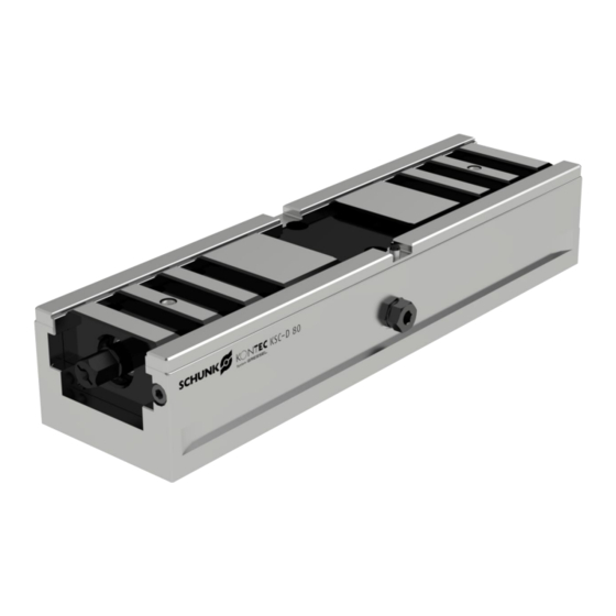
Double vice
KSC-D 80
H.-D. SCHUNK GmbH & Co.
Spanntechnik KG
Lothringer Strasse 23
D-88512 Mengen
schunk.com
XND.00034.002_B – 05/2022
1
Werbung
Inhaltsverzeichnis
Fehlerbehebung

Inhaltszusammenfassung für SCHUNK KSC-D 80
- Seite 1 _________________________________________________________________________________________ Montage- und Betriebsanleitung Installation- and operating instruction Doppelspanner Double vice KSC-D 80 H.-D. SCHUNK GmbH & Co. Spanntechnik KG Lothringer Strasse 23 D-88512 Mengen schunk.com XND.00034.002_B – 05/2022...
-
Seite 2: Inhaltsverzeichnis
10.3 Troubleshooting, eliminating faults ................29 10.4 Removing and replacing parts ..................33 10.5 Fitting the 6-fold reversible jaws ................33 Aluminium jaws ..................33 Fixed jaw vise ..................34 Taking out of service ................34 schunk.com XND.00034.002_B – 05/2022... -
Seite 3: User Information
Important for preventing more extensive material damage CAUTION Indicates a potentially dangerous situation. If the information is ignored, material damage will result. … points out a potentially dangerous situation that can lead to material damage if it is not avoided. schunk.com XND.00034.002_B – 05/2022... -
Seite 4: General Safety Instructions
Weight: KSC-D 80-300 without system jaws: 8.0 kg For further data, please see the catalogue >> Schunk stationary Workholding << 2.2 Reasonably foreseeable misapplication Any application that is not in accordance with the "Intended use" or exceeds such intended use is considered not in accordance with the regulations, and is forbidden. -
Seite 5: Residual Risk
who have completed appropriate induction for working with the machine. who have read and understood these operating instructions. The requirements of the EC Directive 2007/30/EC on the use of work machinery must be complied with. schunk.com XND.00034.002_B – 05/2022... -
Seite 6: Operator Duties
Compliance with the specified maintenance and lubrication intervals. Observance of the maximum service life. Any parts in contact with workpieces are not covered by the warranty. Warranty – maximum service life Warranty period 24 months Maximum service life [clamping cycles] 50,000 schunk.com XND.00034.002_B – 05/2022... -
Seite 7: Description Of The Clamping Device
Since the carriage have a maximum adjustment range of 31 mm, it is possible to clamp two workpieces with different sizes. If this is insufficient, the system jaws can be moved by 25 mm into another groove of the carriage. schunk.com XND.00034.002_B – 05/2022... -
Seite 8: Setting Up The Third-Hand Function
Push parts of the entire carriage unit from the base body to attach the vice. For this purpose, see Section 7 Removal and Section 8 Assembly. Important: The base body and entire carriage must not be interchanged. The parts have been manufactured together and are not interchangeable. schunk.com XND.00034.002_B – 05/2022... -
Seite 9: Corrosion
Important: When using VERO-S clamping bolts, make sure that a shortened screw is used, otherwise the slide may be damage. (See Schunk catalogue) Longitudinal grooves to attach clamping claws. Attachment thread M4 in the base body for alignment using alignment and centring sets. -
Seite 10: Servicing, Cleaning And Maintenance
Remove the central jaw and blow-out the body through the blow-out holes on the front carriager. (pos. 70) Important: Vice functions can exclusively be guaranteed if the central jaw has been installed. Cylinder screw (pos. 210) has not been removed. schunk.com XND.00034.002_B – 05/2022... -
Seite 11: Removal
Fully tighten the clamping screw (pos. 200) and undo by ½ turn. Install the front cylinder screw. (pos. 210) Install the system jaws in the carriages and tightened the cylinder screw (12.9) with a torque of 60 Nm. schunk.com XND.00034.002_B – 05/2022... -
Seite 12: Assembly Drawing
_________________________________________________________________________________________ Assembly drawing schunk.com XND.00034.002_B – 05/2022... -
Seite 13: Parts List
Pos. 10, 60 and 70 cannot be supplied as individual spare parts as these are designed and fitted at the factory to work together. Repairs can be provided by the manufacturer or an authorised service point. schunk.com XND.00034.002_B – 05/2022... -
Seite 14: Swivel And Adapter Plate
Check the peg for soiling. Check that the O-rings are correctly positioned. The upper O-ring must make good contact. Lubricate the entire system with grease and reassemble. schunk.com XND.00034.002_B – 05/2022... -
Seite 15: Removing And Replacing Parts
In view of the fact that clamping may be carried out in different ways, the setting-up technician is responsible for ensuring that adequate clamping cross sections exist and that the workpiece is safely clamped. schunk.com XND.00034.002_B – 05/2022... -
Seite 16: Fixed Jaw Vise
The disassembly to the double clamp is done in reverse order. 13 Taking out of service The clamping device and all accessories can be disposed of as scrap metal without any risk. schunk.com XND.00034.002_B – 05/2022... - Seite 17 _________________________________________________________________________________________ H.-D. Schunk GmbH & Co. Spanntechnik KG Lothringer Strasse 23 D-88512 Mengen Tel.: +49-7572-7614-0 Fax: +49-7572-7614-1099 info@de.schunk.com schunk.com schunk.com XND.00034.002_B – 05/2022...


