Match M 5.4DSP micro Bedienungsanleitung

Verwandte Anleitungen für Match M 5.4DSP micro


Inhaltszusammenfassung für Match M 5.4DSP micro
- Seite 1 M 5.4DSP micro 5-Kanal Miniatur-Verstärker mit 9-Kanal DSP 5-Channel miniature amplifier with 9-channel DSP...
-
Seite 2: Allgemeine Hinweise
MATCH Verstärkers mit integriertem DSP. überzeugende Anwendung ausgereifter Technolo- gien aus. MATCH setzt mit dem M 5.4DSP neue Maßstäbe im Bereich der Verstärkertechnik. Dabei profitieren Viel Freude an diesem Produkt wünscht Ihnen das Sie als Kunde direkt von unserer mehr als 30-jäh-... -
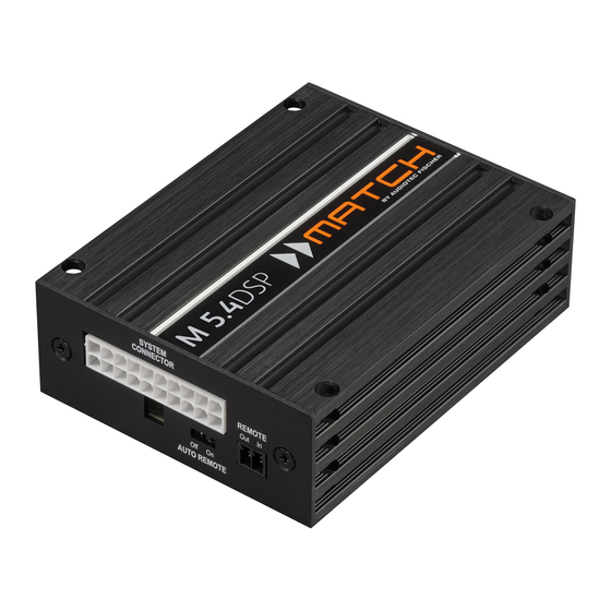
Seite 3: Anschluss- Und Bedienelemente
Anschluss- und Bedienelemente System Connector Remote In / Out Anschluss für den MATCH Kabelbaum. Der Remote-Eingang dient zum Einschalten Verwenden Sie ausschließlich ein MATCH der M 5.4DSP. Der Remote-Ausgang dient Original-Anschlusskabel, um den Verstärker zum Einschalten weiterer Verstärker bei Ver- mit dem Autoradio zu verbinden. - Seite 4 Kabel an die Stromversorgung des Fahr- MATCH Plug & Play Subwoofers, wie beispiels- zeugs angeschlossen werden. Eine ausführliche weise dem MATCH PP 7E-D oder PP 7S-D, eines Beschreibung des „HighPower“-Modus finden Sie herkömmlichen Subwoofers oder Lautsprechers. auf Seite 6.
-
Seite 5: Status Led
Remote-Ausgang sowie die Signalausgabe ab- geschaltet, bis ein sicherer Betrieb wieder gewähr- Dieser Multifunktionsanschluss dient zum Anschluss leistet werden kann. von MATCH Zubehörprodukten, wie beispielsweise grün langsam blinkend: Keine Betriebssoftware einer Fernbedienung mit deren Hilfe diverse Funk- auf dem DSP installiert. Verbinden Sie den Verstär- tionen des DSP-Verstärkers gesteuert werden kön-... -
Seite 6: Umschaltung Der Leistungsmodi
Stromaufnahme der USB-Verlängerung mit integriertem Repeater M 5.4DSP ermöglicht so einen einfachen Anschluss und kein passives USB-Kabel. mit einem optional erhältlichen MATCH-Kabelbaum Optional kann die Verbindung auch mit der (z.B. PP-ISO Kabel) an den Original-Kabelbaum WIFI CONTROL per WLAN hergestellt werden. -
Seite 7: Einbau Und Installation
+12 Volt Abb. 2: Subwoofer Anschlusskabel 8-poliger Molex Stecker – zum Anschluss 2-poliger Molex Stecker – zum Anschluss an eines MATCH Plug & Play Subwoofers den Subwoofer Output der M 5.4DSP ASIA-Steckverbindung Abb. 3: Line Output-to-RCA / Cinch Kabel MicroFit Stecker – zum Anschluss an den Line Output F - I der M 5.4DSP... - Seite 8 Einbau und Installation Der MATCH M 5.4DSP Verstärker wird wie nach- Die Impedanz pro Kanal darf 4 Ohm nicht folgend beschrieben an das Autoradio ange- unterschreiten, da sonst die Schutzschal- tung des Verstärkers aktiviert wird. schlossen. Achtung: Für die Durchführung der nachfolgenden...
- Seite 9 Radio über BTL-Ausgangsstufen verfügt. Schiebereglers die Eingangsempfindlich- keit, bis die Clipping Anzeige erlischt. 5. Konfiguration des Remote-Eingangs Die Einschaltung der MATCH M 5.4DSP erfolgt automatisch bei Ansteuerung über die Hoch- pegel-Lautsprechereingänge oder sobald ein Remote-Signal am Remote-Eingang (Remote 5. Erhöhen Sie die Eingangsempfindlichkeit In) anliegt.
- Seite 10 Folge. Der Pluspol ist bei den meisten Laut- An den Subwooferausgang (Subwoofer Out- sprechern gekennzeichnet. Die Impedanz des put) kann ein passiver MATCH Plug & Play angeschlossenen Lautsprechers darf 2 Ohm Subwoofer, wie beispielsweise ein MATCH nicht unterschreiten, da sonst die Schutzschal- PP 7E-D oder PP 7S-D, ein handelsüblicher...
- Seite 11 Anschluss mit Hilfe eines MATCH Plug & Play Kabels Um die Installation der M 5.4DSP an ein Werks- 4a. Stromversorgung über den Kabelbaum des oder Nachrüstradio deutlich zu vereinfachen, kann Fahrzeugs: der Verstärker auch mit Hilfe von optional erhält- Die Stromversorgung des Verstärkers wird über lichen MATCH Plug &...
- Seite 12 Anschluss mit Hilfe eines MATCH Plug & Play Kabels kabels an das Bordnetz muss die Autobat- Hinweis: MOST-Bus terie abgeklemmt werden. Das +12 V Strom- Bei einigen Fahrzeugen kann es notwendig sein, die kabel (gelb, Abb. 5 / min. 4 mm²) ist am Lichtleiterverbindung aus dem Original-Radioan- Pluspol der Batterie anzuschließen.
- Seite 13 Abb. 5: Direkte Stromversorgung – Voraussetzung für Betrieb im „HighPower“-Modus Diese Seite des Kabelbaums wird direkt an die Batterie angeschlossen. Dafür werden die dafür vorgesehenen Steckverbinder des Kabelbaums getrennt. Gelbe Leitung: +12 Volt Leitung zum Anschluss an den Pluspol der Autobatterie. Schwarze Leitung: Masse-Leitung zum Anschluss an den Minuspol der Autobatterie oder zum An- schluss an einen Massepunkt des Kfz-Chassis.
- Seite 14 PP 7S-D Rear R Full (Anschluss mit beilie- gendem Adapterkabel, + 12 V siehe Seite 10) Hinten Koax- oder Passivsystem Kanalrouting ohne Virtual Channel Processing im DSP PC-Tool für das Konfigurationsbeispiel 1 Für weitere Anwendungsfälle kontaktieren Sie bitte Ihren MATCH-Fachhändler.
- Seite 15 Beispiel 2: HighPower-Modus 5-Kanal Anwendung mit fullrange Frontsystem, fullrange Rearsy- stem und Plug & Play Subwoofer ohne Virtual Channel Processing (VCP) Vorne Passives Frontsystem Front L Full Front R Full MATCH Plug & Play Subwoofer wie z.B. Rear L Full PP 7S-D (Anschluss mit beilie- Rear R Full...
- Seite 16 Konfigurationsbeispiele Beispiel 3: HighPower-Modus 7-Kanal Anwendung mit zusätzlichem 2-Kanal Verstärker und Virtual Anwendungsbeispiel mit MATCH M 2.1AMP für BMW und Mercedes Soundsysteme: Fullrange Frontsystem, Vorne Passives Frontsystem Center 4-Kanal Anschluss vom Autoradio Front L Full Front R Full Speaker Output...
- Seite 17 Channel Processing: Rearsystem, Center und zwei 4 Ohm Subwoofer BMW Untersitz-Subwoofer MW 8BMW-D Vom Verstärker Mercedes Front-Subwoofer UP W8MB-S4 + 12 V 12 V Batterie Spannungs- versorgung Vom Verstärker Für weitere Anwendungsfälle kontaktieren Sie bitte Ihren MATCH-Fachhändler.
-
Seite 18: Anschluss An Den Computer
USB-Kabel an den Computer an. neun DSP Kanäle separat eingestellt werden. Wenn Sie längere Distanzen zu überbrücken Bevor Sie die MATCH M 5.4DSP das erste Mal an haben, verwenden Sie bitte eine aktive USB- Verlängerung mit integriertem Repeater oder einen Computer anschließen, gehen Sie auf unsere... - Seite 19 Virtual Channel Processing (VCP) Das Bedienkonzept des VCP Im Gegensatz zu bisherigen Methoden ist das Virtual Channel Processing (VCP) ein mehrstufiges Signalverarbeitungs-Konzept, welches die perfekte Konfiguration komplexer Soundsysteme ermöglicht und somit ganz neue Möglichkeiten des Klangtunings eröffnet. Die Funktion erweitert den bisherigen Umfang des Gerätes um eine neue Ebene an prozessierten Kanälen, welche sich zwischen den Ein- und Ausgängen befindet.
- Seite 20 Virtual Channel Processing (VCP) – Kanalübergreifender Gruppen-Equalizer Beispielanwendung: Aktives Mehrwege- System Wird ein Eingangssignal (bspw. Vorne links) erst auf einen virtuellen Kanal geroutet (Front L Full) und dieses Signal anschließend auf ein aktives Mehrwege-System geroutet (bspw. Vorne links – Hochtöner, Mitteltöner und Tieftöner), so ist es möglich, mit Hilfe des Equalizers des virtuellen Kanals alle nachgeschalteten einzelnen Kanäle gleichzeitig in ihrer Tonalität zu beeinflussen.
- Seite 21 Konfiguration des Virtual Channel Processing (VCP) Um das VCP zu konfigurieren, muss zuerst das „Virtual Channel Processing“ im DCM-Menü der DSP PC- Tool Software eingeschaltet werden. Gehen Sie dazu in den „Virtual Channel Processing“-Tab und klicken auf die rechte Box mit der VCP-Grafik. Anschließend erfolgt die Konfiguration in drei Schritten – hier am Beispiel einer 3-Wege Konfiguration mit einem 2-Wege Eingangssignal erläutert.
- Seite 22 Konfiguration des Virtual Channel Processing (VCP) Workflow-Schritt 2 – Ausgangsrouting Nachdem alle genutzten Eingangssignale in den jeweiligen Signal-Routing-Matrizen konfiguriert wurden, müssen die virtuellen Kanäle nun den physischen Ausgangskanälen zugeordnet werden. Hierbei kann ein virtuelles Signal (bspw. Front L Full) mehreren Ausgängen zugewiesen werden, wie beispielsweise dem vorderen linken Hochtöner, Mitteltöner und Tieftöner.
- Seite 23 Kanals gleichzeitig in ihrer Tonalität zu beeinflussen. Konfigurationshinweise für die DSP-Soundeffekte (SFX) Die MATCH M 5.4DSP bietet bei aktiviertem Virtual Channel Processing einzigartige DSP-Sound effekte wie das „Augmented Bass Processing“, den „RealCenter“ und mehr. Um in den Genuss der DSP-Soundeffekte zu kommen, müssen bei der Hard- und Softwarekonfiguration bestimmte Einstellungen vorgenommen werden.
- Seite 24 Konfiguration des Virtual Channel Processing (VCP) 2. Wechseln Sie in die „Virtual to Output Routing“ Matrix und routen den Kanal „Virtual E – Front Center Full“ auf den oder die gewünschten Ausgangskanäle (wie im Workflow-Schritt 2 beschrieben), auf wel- che das Center Processing angewendet werden soll. Hinweise zum Eingangsrouting siehe Workflow-Schritt 1 3.
-
Seite 25: Konfiguration Einer Subwoofer-Fernbedienung
Konfiguration einer Subwoofer-Fernbedienung Konfiguration einer Subwoofer-Fernbedienung Zunächst muss die entsprechende Fernbedienung im Tab „Erweiterte Einstellungen“ im DCM Menü der DSP PC-Tool Software aktiviert und je nach Modell konfiguriert werden. Bei nicht aktiviertem VCP ist die Subwoofer-Fernbedienung bei der M 5.4DSP fest den Ausgangskanälen E und F zugeordnet. - Seite 26 ACO Plattform-Features Neben den einzigartigen DSP-Sound effekten bietet Remote Output Configuration die ACO-Plattform der M 5.4DSP zusätzlich eine An dieser Stelle kann festgelegt werden, ob der Vielzahl an System-Features. Remote-Ausgang, angeschlossenen Im DCM Menü der DSP PC-Tool Software können Endstufen ein- bzw. ausschaltet, während eines für einige dieser System-Features individuelle Sound-Setup-Wechselvorgangs kurzzeitig deakti- Einstellungen vorgenommen werden.
- Seite 27 Flashspeichers Platz für 10 Sound Setups anstelle der üblichen zwei. Start-Stopfähigkeit Das Netzteil im MATCH M 5.4DSP stellt die interne Spannungsversorgung auch bei kurzfristigen Ein- brüchen bis hinab zu 6 Volt sicher. Damit ist gewährleistet, dass der MATCH M 5.4DSP...
-
Seite 28: Technische Daten
Technische Daten Leistung RMS - Kanal A - D ..............4 x 60 Watt @ 4 Ohm (HighPower) 4 x 35 Watt @ 4 Ohm (MidPower) - Sub Out ................1 x 90 Watt @ 4 Ohm (High- & MidPower) 1 x 160 Watt @ 2 Ohm (High- &... - Seite 56 Audiotec Fischer GmbH Hünegräben 26 · 57392 Schmallenberg · Germany Tel.: +49 2972 9788 0 · Fax: +49 2972 9788 88 E-mail: match@audiotec-fischer.com · Internet: www.audiotec-fischer.com...