Match UP 7DSP Einbau Und Installation

Verwandte Anleitungen für Match UP 7DSP


Inhaltszusammenfassung für Match UP 7DSP
- Seite 1 UP 7DSP U P G R A D E 7-Kanal Upgrade-Verstärker mit integriertem 8-Kanal 64 Bit DSP für universelle Anwendungen 7-channel upgrade amplifier with integrated 8-channel 64 Bit DSP for universal applications...
-
Seite 2: Allgemeine Hinweise
MATCH Verstärkers mit integriertem DSP. und eine überzeugende Anwendung ausgereifter Technologien aus. MATCH setzt mit dem UP 7DSP neue Maßstäbe im Viel Freude an diesem Produkt wünscht Ihnen das Bereich der Verstärkertechnik. Dabei profitieren Sie als Kunde direkt von unserer mehr als 30-jährigen... -
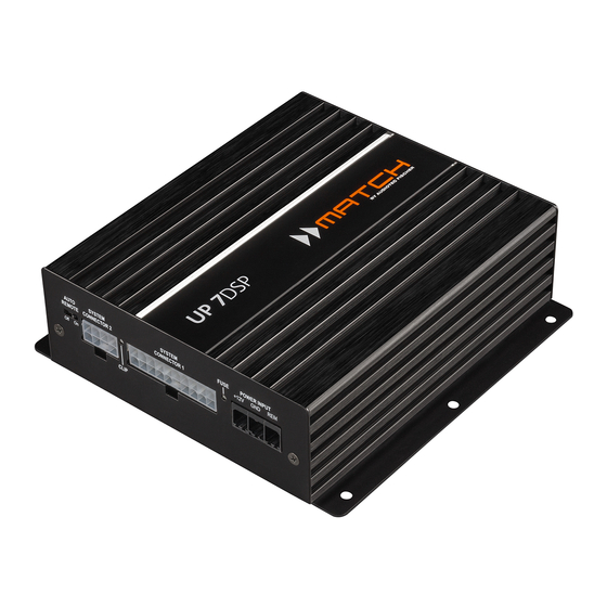
Seite 3: Anschluss- Und Bedienelemente
Control Input Mono-Vorverstärkerausgang zum Anschluss Multifunktionsanschluss - dient zum An- weiterer Verstärker. Zum Einschalten dieser schluss einer Fernbedienung und weiterem Verstärker muss der Remote-Ausgang ver- MATCH UP 7DSP Zubehör. wendet werden. Optical Input Optischer Eingang im SPDIF-Format für digi- tale Stereosignale. - Seite 4 8 REM schen der Garantie. Der Remote-Eingang dient zum Einschalten der 3 Clipping LED UP 7DSP, sofern die am System Connector 1 an- Diese LED leuchtet rot, wenn einer der vier Hoch- geschlossene Signalquelle die automatische Ein- pegel-Lautsprechereingänge übersteuert wird. Die...
- Seite 5 9 USB Eingang Die „Sampling Rate“ dieses Eingangs muss zwi- Mit Hilfe dieses Eingangs wird die UP 7DSP über schen 12 - 96 kHz liegen. Das Eingangssignal wird das beiliegende Kabel mit dem Computer verbun- automatisch an die interne Abtastrate angepasst.
- Seite 6 Spezielle Features der UP 7DSP Class HD Technologie Automatic Digital Signal Detection In der UP 7DSP werden die Vorteile der Class H- Die Umschaltung zwischen den analogen und dem Technologie mit dem Prinzip eines Class D Ver- Digitaleingang erfolgt signalgesteuert. Sobald ein stärkers kombiniert.
-
Seite 7: Einbau Und Installation
Einbau und Installation Abb. 1: Pinbelegung System Connector 1 und 2 21 22 23 24 25 26 27 28 11 12 13 14 15 16 17 18 19 20 System Connector 1 Highlevel-Lautsprechereingang hinten links (-) / C Highlevel-Lautsprechereingang hinten links (+) / C Highlevel-Lautsprechereingang vorne links (-) / A Highlevel-Lautsprechereingang vorne links (+) / A Highlevel-Lautsprechereingang vorne rechts (-) / B... - Seite 8 Einbau und Installation Der MATCH UP 7DSP Verstärker wird wie nach- Die Impedanz pro Kanal darf 4 Ohm nicht folgend beschrieben montiert und angeschlos- unterschreiten, da sonst die Schutzschal- sen. tung des Verstärkers aktiviert wird. 2. Anschluss des System Connector 2 Achtung: Für die Durchführung der nachfolgenden...
- Seite 9 Die Einschaltung der MATCH UP 7DSP erfolgt bedeutet, dass an sämtlichen Ausgängen der automatisch bei Ansteuerung über die Hoch- UP 7DSP der volle Pegel anliegt. Dies kann im pegel-Lautsprechereingänge des System Con- Extremfall die angeschlossenen Lautsprecher nectors 1 oder sobald ein Remote-Signal am zerstören.
-
Seite 10: Anschluss Mit Hilfe Des Pp-Iso Kabels
Signal zur Einschaltung externer Verstärker, um Ein- und Ausschaltgeräusche zu vermeiden. Anschluss mit Hilfe des PP-ISO Kabels Um die Installation der UP 7DSP an ein Werks- oder siehe Abb. 3 . Nachdem die Kabelverbin- Nachrüstradio deutlich zu vereinfachen, kann der dungen getrennt wurden müssen die offenen... - Seite 11 Kabelbaums (gelb und schwarz). Nachdem die Kabelverbindungen getrennt wurden, müssen die offenen Enden einzeln isoliert werden. Der Stromanschluss der UP 7DSP wird mit Hilfe eines geeigneten Kabels (Querschnitt min. 10 mm²) direkt an die Batterie angeschlossen - die Plusleitung muss kurz vor der Batterie noch einmal abgesichert werden.
-
Seite 12: Anschluss An Den Computer
Die Software sowie die dazugehörige Bedienungsan- aktuell ist, wird diese automatisch aktualisiert. leitung finden Sie auf www.audiotec-fischer.com. 4. Nun können Sie die UP 7DSP mithilfe der DSP Es wird dringend empfohlen die Bedienungsanlei- PC-Tool Software frei konfigurieren. Nützliche tung der Software (Sound Tuning Magazin) vor der Hinweise zur korrekten Einstellung entnehmen Sie z.B. -
Seite 13: Konfigurationshinweise Für Die Dsp-Soundeffekte
Konfigurationshinweise für die DSP-Soundeffekte Der MATCH UP 7DSP bietet einzigartige DSP- Hinweis: Das Center Processing wird ausschließ- Sound effekte wie das „Augmented Bass Proces- lich auf den Ausgangskanal G angewendet. sing“, den „StageXpander“, den „RealCenter“ und noch mehr. Hinweise für StageXpander- Um jedoch in den Genuss aller DSP-Soundeffekte ClarityXpander-Funktion zu kommen, müssen bei der Hard- und Software-... - Seite 14 Konfigurationsbeispiele 7-Kanal Anwendung mit Center und 2 x 2 Ohm Subwoofer 2-Wege Passivsystem + Koaxialsystem + Center + Subwoofer mit Doppelschwingspule (Dual Voice Coil) Vorne Links Rechts SW 1 SW 2 Links Rechts 2 x 2 Ohm Subwoofer Center Hinten SW = Schwingspule 7-Kanal Anwendung mit 2-Wege Aktivsystem, Center und zwei 1 x 2 Ohm Subwoofern Hochtöner + Tiefmitteltöner + Center + zwei Subwoofer mit einer Schwingspule (Single Voice Coil)
-
Seite 15: Einbau Einer Match Extension Card
Audio USB Soundkarte etc. erweitert wer- den. Zur Montage einer MEC muss das Seitenblech der UP 7DSP demontiert und gegen das der MEC bei- liegende Seitenblech ausgetauscht werden. Achtung: Installieren Sie ausschließlich für den UP 7DSP Verstärker vorgesehene MEC Module an der dafür vorgesehenen Position. -
Seite 16: Technische Daten
Technische Daten Leistung RMS / Max. - @ 4 Ohm ...............5 x 65 / 130 Watt (Front / Rear / Center Kanäle) - Subwooferausgang an 2 Ohm……………………………2 x 160 / 320 Watt Verstärkertechnologie ............Class HD Eingänge .................4 x Hochpegel-Lautsprechereingang 1 x Optisch SPDIF (12 - 96 kHz) 1 x MEC 1 x Remote In Eingangsempfindlichkeit ..........Hochpegel 5 - 11 Volt... - Seite 32 Audiotec Fischer GmbH Hünegräben 26 · 57392 Schmallenberg · Germany Tel.: +49 2972 9788 0 · Fax: +49 2972 9788 88 E-mail: match@audiotec-fischer.com · Internet: www.audiotec-fischer.com...