Inhaltsverzeichnis
Werbung
Verfügbare Sprachen
Verfügbare Sprachen
Werbung
Kapitel
Inhaltsverzeichnis

Verwandte Anleitungen für Carrier CRC2 - NTC


Inhaltszusammenfassung für Carrier CRC2 - NTC
- Seite 1 CRC2 - NTC Carrier Room Controller 2 2 WAY INSTALLATION MANUAL MONTAGE-INSTRUCTIES MANUALE DI INSTALLAZIONE MANUEL D’INSTALLATION MANUAL DE INSTALAÇÃO INSTALLATIONSANWEISUNG INSTALLATIONSMANUAL MANUAL DE INSTALACIÓN ASENNUSOHJE...
- Seite 2 NTC - Carrier Room Controller 2 ENGLISH Installation Manual ITALIANO Manuale di installazione FRANÇAIS Manuel d’installation DEUTSCH Installationsanweisung ESPAÑOL Manual de instalación NEDERLANDS Montage-Instructies PORTUGUÊS Manual de instalação SVENSKA Installationsmanual SUOMI Asennusohje...
-
Seite 3: Inhaltsverzeichnis
NTC Room Controller 2 Installation manual This control system only operates with all hydronic indoor units. Contents Page Aspect and display ............................General information ............................Choosing the installation site ........................Installation ................................. Electrical connections ........................... Room controller 2 confi guration ......................... Troubleshooting .............................. -
Seite 4: Aspect And Display
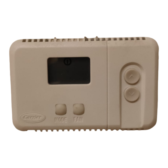
NTC Room Controller 2 Aspect and display A = Display C = Key for selecting the operating mode D = Key for increasing temperature/changing louver setting E = Button for selecting the fan speed F = Key for decreasing temperature/changing louver setting S = Room temperature sensor V = Back panel fi xing screws... -
Seite 5: General Information
NTC Room Controller 2 General information E N G L I S H IMPORTANT: Room Controller 2: Hydronic Fancoil Solutions Read the entire instruction manual before starting the installation. • For trouble-free installation, which should be carried out by a qualifi ed installer, follow the installation chart sequence. -
Seite 6: Installation
NTC Room Controller 2 Installation Mounting • Match and connect equipment wires to proper terminals in the connector block. Both power and communication wires must be connected correctly for proper Room Controller operation. WARNING: Before installing the Room Controller 2, turn off all power to the Unit that will supply power to the Room Controller 2. -
Seite 7: Electrical Connections
NTC Room Controller 2 Electrical connections and Room Controller 2 confi guration E N G L I S H Connection of Room Controller 2 to the NTC Remove the main board from the control panel box for easier access to electric connections. control panel box. -
Seite 8: Room Controller 2 Confi Guration
NTC Room Controller 2 Room Controller 2 confi guration, troubleshooting Confi guration table for NTC units Item Value Description Displayed °C Temperatures displayed in degrees C °F Temperatures displayed in degrees F System - CRC2 will be used with a communicating system Stand alone system - The CRC2 will be used with a non-communicating system Temperature displaying No temperature is displayed... -
Seite 9: Dimensioni (Mm)
NTC Room Controller 2 Manuale di installazione Questo sistema di controllo funziona con tutte le unità interne idroniche. Indice Pagina Aspetto e display ............................. Informazioni generali ............................ Scelta del luogo di installazione ........................Installazione ..............................Collegamenti elettrici ............................. Confi gurazione Room Controller 2 ......................Problemi e soluzioni ............................ -
Seite 10: Aspetto E Display
NTC Room Controller 2 Aspetto e display A = Display C = Selezione della modalità di funzionamento D = Incrementare la temperatura/modifi ca impostazioni louver E = Selezione velocità ventilatore F = Decrementare la temperatura/ modifi ca impostazione louver S = Sensore di temperatura ambiente V = Viti fi ssaggio pannello posteriore Spento Temperatura desiderata/temperatura ambiente... -
Seite 11: Informazioni Generali
NTC Room Controller 2 Informazioni generali I T A L I A N O IMPORTANTE: Leggere attentamente questo manuale prima di iniziare Room Controller 2 : Soluzioni con ventilconvettori idronici l’installazione. • L’installazione deve essere eseguita da personale specializzato rispettando la sequenza di operazioni indicata nello schema d’installazione. -
Seite 12: Installazione
NTC Room Controller 2 Installazione Montaggio • Collegare i cavi ai relativi terminali sulla morsettiera. I cavi di alimentazione e quelli di comunicazione devono essere collegati correttamente per un buon funzionamento del Room Controller 2. ATTENZIONE: Prima di installare il Room Controller 2, togliere l'alimentazione elettrica verso l'unità... -
Seite 13: Collegamenti Elettrici
NTC Room Controller 2 Collegamenti elettrici e confi gurazione Room Controller 2 I T A L I A N O Collegamento del Room Controller 2 al quadro Si consiglia di sfi lare la scheda principale dal quadro elettrico per consentire un miglior accesso alle connessioni elettriche. elettrico NTC. -
Seite 14: Confi Gurazione Room Controller
NTC Room Controller 2 Confi gurazione Room Controller 2, problemi e soluzioni Tabella di confi gurazione per le unità NTC Item Valore Descrizione Visualizzato °C Temperatura visualizzata in gradi C °F Temperatura visualizzata in gradi F Sistema - Il CRC2 sarà utilizzato su un sistema comunicante Stand alone system - Il CRC2 sarà... - Seite 15 NTC Room Controller 2 Manuel d'installation Ce dispositif de contrôle fonctionne uniquement avec toutes les unités intérieures hydrauliques. Table des Matières Page Aspect et affi chage ............................Informations générales ..........................Choix du site d’installation ..........................Installation ................................. Les branchements électriques ........................Confi guration du Room Controller 2 ......................
- Seite 16 NTC Room Controller 2 Aspect et affi chage A = Affi chage C = Touche pour la sélection de la modalité de fonctionnement D = Augmenter la température / modifi er paramétrage louver E = Touche pour la sélection de la vitesse de ventilation F = Diminuer la température / modifi er paramétrage louver S = Capteur de température ambiante V = Vis de fi xation du panneau arrière...
- Seite 17 NTC Room Controller 2 Informations générales F R A N Ç A I S IMPORTANT: Room Controller 2 : Solutions de ventilo-convecteurs hydrauliques Lire attentivement ce manuel d’instructions avant de commencer la mise en place de l’appareil. • Pour une installation sans problème, il est important de la faire exécuter par un installateur spécialisé...
- Seite 18 NTC Room Controller 2 Installation Montage • Connecter les câbles avec la borne correspondante sur la barrette de raccordement et les connecter. Il est nécessaire que les câbles d’alimentation et de communication soient branchés correctement pour que le Room Controller 2 fonctionne. AVERTISSEMENT: Avant d’installer le Room Controller 2, déconnecter toutes les sources d’énergie de l’unité...
- Seite 19 NTC Room Controller 2 Les branchements électriques et confi guration du Room Controller 2 F R A N Ç A I S Câblage du Room Controller 2 au panneau Il est conseillé de défi ler la carte principale du panneau électrique pour faciliter l’accès aux branchements électriques.
- Seite 20 NTC Room Controller 2 Confi guration du Room Controller 2, dépistage des problèmes de fonctionnement Tableau de confi guration pour les unités NTC Article Valeur Description Affi chée °C Températures affi chées en degrés C °F Températures affi chées en degrés F Système - CRC2 sera utilisé...
-
Seite 21: Abmessungen (Mm)
NTC Room Controller 2 Installationshandbuch Diese Kontrolleinheit funktioniert mit allen Hydronischen Innengeräten. Inhalt Seite Aussehen und Display ............................ Allgemeine Informationen .......................... Wahl des Installationsorts ..........................Installation ................................. Elektroanschlüsse ............................Room Controller 2-Konfi guration ....................... Störungsermittlung ............................INSTALLATIONSDIAGRAMM Handbuch lesen Room Controller 2 installieren Den Room Controller 2 und Gerät herstellen... -
Seite 22: Ntc Room Controller 2 Aussehen Und Display
NTC Room Controller 2 Aussehen und Display A = Display C = Taste zur Wahl der Betriebsweise D = Temperaturerhöhung/Änderung der Einstellung der Luftklappen E = Taste zur Wahl der Belüftungsgeschwindigkeit F = Temperaturreduzierung/ Änderung der Einstellung der Luftklappen S = Sensor der Raumtemperatur V = Befestigungsschrauben der hinteren Abdeckung Ausgeschaltet Gewünschte Temperatur/Raumtemperatur... -
Seite 23: Allgemeine Informationen
NTC Room Controller 2 Allgemeine Informationen D E U T S C H WICHTIG: Room Controller 2: Hydronische Umluftgebläseeinheiten Lesen Sie dieses Handbuch sorgfältig durch, bevor Sie das Gerät einschalten. • Die Reihenfolge des Installationsdiagramms befolgen, um eine problemlose Installation zu gewährleisten. Diese darf nur von einem Fachinstallateur vorgenommen werden. -
Seite 24: Installation
NTC Room Controller 2 Installation Montage • Die zusammengehörigen Gerätekabel an die korrekten Klemmen auf dem Klemmblock anschließen. Für korrekten Betrieb des Room Controllers 2 müssen sowohl Versorgungs- als auch Kommunikationskabel korrekt angeschlossen werden. ACHTUNG: Vor der Installation des Room Controllers 2 das Gerät, das den Room Controller 2 versorgt, ausschalten. -
Seite 25: Elektroanschlüsse
NTC Room Controller 2 Elektroanschlüsse und Room Controller 2 Konfi guration D E U T S C H Verbindung des Room Controllers 2 an das NTC Man empfi ehlt, die Hauptplatine von der Schalttafel herauszuziehen, um einen besseren Zugriff zu den elektrischen Anschlüssen zu Schaltbrett ermöglichen. -
Seite 26: Konfi Gurationstabelle Für Das Gerät Ntc
NTC Room Controller 2 Room Controller 2 Konfi guration, Störungsermittlung Konfi gurationstabelle für das Gerät NTC Pos. Wert Beschreibung Am Display angezeigt °C Temperaturen in Grad C angezeigt NEIN °F Temperaturen in Grad F angezeigt System: CRC2 wird mit einem kommunizierenden System benutzt NEIN System Stand Alone :CRC2 wird mit einem nicht kommunizierenden System benutzt Temperaturanzeige... -
Seite 27: Dimensiones (Mm)
NTC Room Controller 2 Manual de instalación Este dispositivo de control funciona con todos las unidades internas hidrónicas. Índice Página Aspecto y display ............................Informaciones generales ..........................Elección del lugar de instalación ........................ Instalación ................................ Conexiones eléctricas ........................... Confi guración del Room Controller 2 ....................... Localización de averías .......................... -
Seite 28: Aspecto Y Display
NTC Room Controller 2 Aspecto y display A = Display C = Selección de la modalidad de funcionamiento D = Aumentar la temperatura/modifi cación confi guración louver E = Selección velocidad del ventilador F = Disminuir la temperatura/modifi cación confi guración louver S = Sensor de temperatura ambiente V = Tornillos de sujeción panel trasero... -
Seite 29: Informaciones Generales
NTC Room Controller 2 Informaciones generales E S P A Ñ O L IMPORTANTE: Room Controller 2: Soluciones Fan Coil Hidrónicos Leer atentamente este manual de instruc ciones antes de iniciar la instalación del aparato. • Para una instalación sin problema, es importante que la colocación y conexión se hagan por parte de un instalador especializado siguiendo el orden de operaciones aquí... -
Seite 30: Instalación
NTC Room Controller 2 Instalación Montaje • Acoplar los cables con el borne correspondiente del bloque terminal y conectarlo. Para que el Room Controller funcione, es necesario que los cables de suministro y de comunicación estén conectados correctamente. ADVERTENCIA: Antes de instalar el Room Controller 2, desconectar todas las fuentes de energía de la unidad destinada a suministrar corriente al Room Controller 2. -
Seite 31: Conexiones Eléctricas
NTC Room Controller 2 Conexiones eléctricas y confi guración del Room Controller 2 E S P A Ñ O L Conexión del Room Controller 2 al cuadro Es aconsejable extraer la tarjeta principal del cuadro eléctrico para facilitar el acceso a las conexiones eléctricas. eléctrico NTC La conexión del Room Controller 2 debe ser realizada según el ADVERTENCIA: Antes de enchufar el Room Controller 2,... -
Seite 32: Confi Guración Del Room Controller
NTC Room Controller 2 Confi guración del Room Controller 2, localización de averías Tabla de confi guración para las unidades NTC Item Valor Descripción Visualización °C Temperaturas visualizadas en grados C °F Temperaturas visualizadas en grados F Sistema - CRC2 se utilizará con un sistema comunicante Sistema stand alone - CRC2 se utilizará... -
Seite 33: Afmetingen (Mm)
NTC Room Controller 2 Montage-Instructies Deze regelaars werken met alle typen ventilatorconvectoren uitgevoerd met een NTC regelaar: Inhoud Blz. Regelaar en display ............................. Algemene informatie ..........................Plaats van opstelling ........................... Montage ................................. Elektrische aansluitingen .......................... Confi guratie van de Room Controller 2 ....................Storingzoeken .............................. -
Seite 34: Regelaar En Display
NTC Room Controller 2 Regelaar en display A = Display C = Bedrijfstype D = Temperatuur verhogen/ wijzigen stand toevoerluchtrooster E = Keuze ventilatorsnelheid F = Temperatuur verlagen/ wijzigen stand toevoerluchtrooster S = Sensor ruimteluchttemperatuur V = Bevestigingsschroeven achterpaneel Gewenste temperatuur / Ruimteluchttemperatuur Niet gebruikt *Stand toevoerluchtrooster Ventilatorsnelheid... -
Seite 35: Algemene Informatie
Wanneer men zich niet houdt aan de montage-instructies dan vervalt de garantie. • Controleer de zending bij aankomst op transportschade. Meld eventuele zichtbare schade onmiddellijk telefonisch aan Carrier en laat de vervoerder een aantekening maken op de vrachtbrief. Installeer of gebruik geen beschadigde apparatuur. •... -
Seite 36: Montage
NTC Room Controller 2 Montage Montage • Sluit de bedrading van de unit aan op de juiste klemmen op de klemmenstrook. Zowel voedings- als communicatiekabels moeten correct worden aangesloten voor een goede werking van de Room Controller 2. WAARSCHUWING: Voordat u de Room Controller 2 gaat monteren moet de hoofdstroom worden uitgeschakeld. -
Seite 37: Elektrische Aansluitingen
NTC Room Controller 2 Elektrische aansluitingen en confi guratie van de Room Controller 2 N E D E R L A N D S Aansluiting Room Controller 2 op de-unit Voor betere toegang tot de elektrische aansluitingen raden wij u aan om de afdekpanelen van het regelpaneel te verwijderen. -
Seite 38: Storingzoeken
NTC Room Controller 2 Confi guratie van de Room Controller 2, Storingzoeken Confi guratietabel voor de NTC-eenheden Item Waarde Beschrijving Afgebeeld °C Temperatuur afgebeeld in graden C °F Temperatuur afgebeeld in graden F Communicerend systeem - CRC2 wordt gebruikt met een communicerend systeem Stand alone- systeem - CRC2 wordt gebruikt met een niet communicerend systeem Afbeelden van de temperatuur Er wordt geen temperatuur afgebeeld... - Seite 39 NTC Room Controller 2 ............................................................................................... 2 ) ....................... Room Controller 2 (mm) GR - 1...
- Seite 40 NTC Room Controller 2 GR - 2...
- Seite 41 NTC Room Controller 2 • • • • • • • • • 12 VDC • • • • • • • • : 150 GR - 3...
- Seite 42 NTC Room Controller 2 • 6 mm 6 mm • ) 2, LED. • • • • • • 5 mm, • ’ PVC, ø 30 mm. 30 mm GR - 4...
- Seite 43 NTC Room Controller 2 Room Controller2 : BELDEN 9842. ³ +12 V (P) • • (BELDEN 9842). mm2, (H03VV-F).(H03VV-F). • MODE 1− • 1− MODE. UP ( DOWN ( MODE ( 1−. • UP ( ) DOWN ( down MODE (3−, 4−...
- Seite 44 NTC Room Controller 2 Room Controller 2, °C (°C) °F (°F) : CRC2 CRC2 (set-point) 32 °C 90 °F) 1°, 26 °C 76 °F) 2°, 30 °C ; 80 °F) = 0° (C 0°, 0=0°C 0°F 22 °C 72 °F) = 1 °C 0,9 °F 1=0,5°C 0,9°F...
- Seite 45 NTC Room Controller 2 Manual de instalação Este sistema de controlo funciona com todas as unidades internas hidrónicas. Índice Página Aspecto e ecrã .............................. Informações gerais ............................Escolha do lugar da instalação ......................... Instalação ............................... Ligações eléctricas ............................Confi guração Room Controller 2 ......................Problemas e soluções ..........................
-
Seite 46: Aspecto E Ecrã
NTC Room Controller 2 Aspecto e Ecrã A = Ecrã C = Selecção da modalidade de funcionamento D = Incrementar a temperatura/alteração confi guração grelhas de alimentação (louver) E = Selecção da velocidade ventilador F = Decrementar a temperatura/alteração confi guração grelhas de alimentação (louver) S = Sensor de temperatura ambiente V = Parafusos de fi xação painel traseiro... -
Seite 47: Informações Gerais
NTC Room Controller 2 Informações gerais PORTUGUÊS IMPORTANTE: Antes de iniciar a instalação este manual deve ser lido com atenção. Room Controller 2: Soluções de Ventilo-convector hidrônico • A instalação deve ser efectuada por pessoal especializado, com o respeito da sequência de operações indicada no esquema de instalação. -
Seite 48: Instalação
NTC Room Controller 2 Instalação Instalação • Ligue os fi os aos relativos terminais na régua de bornes. Os fi os de alimentação e aqueles de comunicação devem ser ligados correctamente para um bom funcionamento do Room Controller 2. ATENÇÃO: Antes de instalar o Room Controller 2, tire a alimentação eléctrica na unidade que alimentará... -
Seite 49: Ligações Eléctricas
NTC Room Controller 2 Ligações eléctricas e confi guração Room Controller 2 PORTUGUÊS Ligação do Room Controller 2 no painel eléctrico Recomenda-se para extrair a placa principal do quadro eléctrico a fi m de permitir um melhor acesso às conexões eléctricas. NTC. -
Seite 50: Problemas E Soluções
NTC Room Controller 2 Confi guração do Room Controller 2, problemas e soluções Tabela de confi guração para as unidades NTC Item Valor Descrição Visualização °C Temperaturas visualizadas em graus C NÃO °F Temperaturas visualizadas em graus F Sistema - CRC2 deverá ser usado com um sistema de comunicação NÃO Sistema independente - O CRC2 será... - Seite 51 NTC Room Controller 2 Installationsmanual Detta kontrollsystem fungerar endast med de interna hydroniska enheterna. Innehållsförteckning Sida Utseende och display ..........................Allmän information ............................. Val av installationsplats ..........................Installation ..............................Elanslutningar .............................. Konfi gurering av Room Controller 2 ..................... Problem och lösningar..........................INSTALLATIONSSCHEMA Läsning av manualen Installation av...
- Seite 52 NTC Room Controller 2 Utseende och display A = Display C = Val av funktionssätt D = Höj temperaturen/ändra inställning av ventilationsgaller E = Val av fl äkthastighet F = Sänk temperaturen/ändra inställning av ventilationsgaller S = Temperatursensor för omgivning V = Fäsktskruvar bakre panel Släckt Önskad temperatur / omgivningstemperatur...
-
Seite 53: Val Av Installationsplats
NTC Room Controller 2 Allmän information S V E N S K A VIKTIGT! Läs denna manual noggrant innan installationen påbörjas. Room Controller 2: Hydroniska Fancoil-lösningar • Installationen ska utföras av specialiserad personal med respekt för ordningsföljden som anges i installationsschemat. •... - Seite 54 NTC Room Controller 2 Installation Montering • Anslut kablarna till respektive kabelfästen på kopplingsplinten. Matnings- och kommunikationskablarna ska anslutas på ett korrekt sätt för att Room Controller 2 ska fungera på ett bra sätt. OBSERVERA! Innan Room Controller 2 installeras ska elmatningen till enheten som strömförsörjer Room Controller 2 kopplas från.
- Seite 55 NTC Room Controller 2 Elanslutningar och konfi gurering av Room Controller 2 S V E N S K A Anslutning av Room Controller 2 till elskåp NTC. Det rekommenderas att dra ut huvudelkortet från elpanelen för att bättre komma åt elanslutningarna. Anslutningen av Room Controller 2 ska göras enligt ritningen till OBSERVERA! Innan någon typ av anslutning görs ska elmatningen till vänster.
-
Seite 56: Problem Och Lösningar
NTC Room Controller 2 Konfi gurering av Room Controller 2, problem och lösningar Konfi gurationstabell för NTC-enheterna Värde Beskrivning Display °C Temperatur visad i Celsius °F Temperatur visad i Farenheit System - CRC2 ska användas med ett kommunikationssystem St Fristående system - CRC2 ska användas på ett ej kommunicerande system Temperaturvisning Ingen temperatur visas på... - Seite 57 NTC Room Controller 2 Asennusohje Tämä ohjausjärjestelmä toimii ainoastaan kaikkien sisäyksiköiden kanssa. Sisältö Sivu Ulkomuoto ja näyttö ..........................Yleistiedot ..............................Asennuspaikan valinta ..........................Asennus................................. Sähkökytkennät ............................Room Controller 2:n asetukset ........................ Ongelmat ja ratkaisut..........................ASENNUSKAAVIO Oppaan lukeminen Room Controller 2:n asentaminen RC:n kytkeminen verkkoon...
- Seite 58 NTC Room Controller 2 Ulkomuoto ja näyttö A = Näyttö C = Toimintatilan valinta D = Lämpötilan lisääminen / säleikön asetusten muuttaminen E = Puhaltimen nopeuden valinta F = Lämpötilan pienentäminen / säleikön asetusten muuttaminen S = Ympäristön lämpötila-anturi V = Takapaneelin kiinnitysruuvit Pois päältä...
- Seite 59 NTC Room Controller 2 Yleistiedot ja asennuspaikan valinta S U O M I TÄRKEÄÄ: Lue tämä opas huolellisesti ennen asennuksen aloittamista. Room Controller 2: Hydroniset puhallinkonvektoriratkaisut • Asennuksen saa suorittaa ainoastaan pätevä henkilö asennuskaaviossa esitetyssä toimintajärjestyksessä. • Asennus on suoritettava noudattaen voimassa olevia kansallisia turvallisuusmääräyksiä.
- Seite 60 NTC Room Controller 2 Asennus Asennus • Liitä johdot kytkentäriman vastaaviin liittimiin. Syöttöjohdot ja yhteysjohdot on liitettävä oikein, jotta Room Controller 2 toimii hyvin. HUOM: Ennen Room Controller 2:n asentamista on katkaistava virransyöttö yksikköön, josta Room Controller 2 saa virran. Sähköiskut voivat aiheuttaa erittäin vakavan tapaturman.
- Seite 61 NTC Room Controller 2 Room Controller 2:n sähkökytkennät ja asetukset S U O M I Room Controller 2:n kytkeminen NTC- On suositeltavaa ottaa pääpiirilevy ulos sähkötaulusta, jotta sähkökytkennät olisi helpompi tehdä. sähkötauluun. Room Controller 2 on kytkettävä vasemmanpuoleisen kuvan HUOM.: mukaisesti.
- Seite 62 NTC Room Controller 2 Room Controller 2:n asetukset, ongelmat ja ratkaisut NTC-yksiköiden asetusten taulukko Asetus Arvo Kuvaus Näytetään °C Lämpötilat näytetään celsiusasteina °F Lämpötilat näytetään fahrenheitasteina Järjestelmä : CRC2:ta käytetään toisiin järjestelmiin yhteydessä olevan järjestelmän kanssa Erillisjärjestelmä: CRC2:ta käytetään erillisenä järjestelmänä, joka ei ole yhteydessä toisiin järjestelmiin Lämpötilanäyttö...
- Seite 64 L010126H69 - 0209 Carrier EMEA Replacement Components Division, route de Thil, 01120 Montluel France www.carrier-ercd.com The manufacturer reserves the right to change any product specifi cations without notice. La cura costante per il miglioramento del prodotto può comportare senza preavviso, cambiamenti o modifi che a quanto descritto.