Herunterladen Inhalt Inhalt Diese Seite drucken
Inhaltsverzeichnis

Werbung

Verfügbare Sprachen

Verfügbare Sprachen

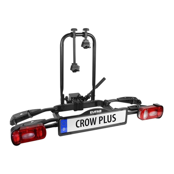
Art.-Nr.: 11582
Fahrradträger CROW PLUS, erweiterbar
Bedienungsanleitung .......................................... 3
Article number 11582
Bicycle rack CROW PLUS, can be expanded
Operating instructions ........................................ 8
11582_manual_ML_Eufab_EAL_11.2020_neu.indd 1
© EAL GmbH, 11582, 11.2020
Réf. 11582
Porte-vélos CROW PLUS, extensible
Manuel de l'opérateur ........................................ 13
Cod. art. 11582
Portabiciclette CROW PLUS, espandibile
Istruzioni per l'uso ................................................. 18
1
04.11.20 14:10
04.11.20 14:10

Werbung

Inhaltsverzeichnis
loading

Inhaltszusammenfassung für Eufab CROW PLUS

  • Seite 1 Porte-vélos CROW PLUS, extensible Bedienungsanleitung .......... 3 Manuel de l‘opérateur ........13 Article number 11582 Cod. art. 11582 Bicycle rack CROW PLUS, can be expanded Portabiciclette CROW PLUS, espandibile Operating instructions ........8 Istruzioni per l‘uso ..........18 11582_manual_ML_Eufab_EAL_11.2020_neu.indd 1 11582_manual_ML_Eufab_EAL_11.2020_neu.indd 1...
  • Seite 2 11582_manual_ML_Eufab_EAL_11.2020_neu.indd 2 11582_manual_ML_Eufab_EAL_11.2020_neu.indd 2 04.11.20 14:10 04.11.20 14:10...
  • Seite 3: Inhaltsverzeichnis

    3.1 KUPPLUNGSVORAUSSETZUNGEN Fahrradträger CROW PLUS, erweiterbar • Die Anhängerkupplung muss bauartgenehmigt sein. • Kugel und Kugelstange müssen einteilig geschmiedet sein. INHALT • Montieren Sie den Fahrradträger nur an eine Kupplung aus Stahl St52-3, BESTIMMUNGSGEMÄSSER GEBRAUCH _________________ 3 Grauguß GGG52 oder besserer Güte.
  • Seite 4: Bedienungsanleitung

    Personen- oder Sachschaden durch überstehende Teile • Über den Rand des Fahrzeugs bzw. Fahrradträgers stehende Teile können während der Fahrt Personen- oder Sachschäden verursachen. • Montieren Sie nur Teile, die nicht über den Rand des Fahrzeugs heraus- ragen. Personen- oder Sachschaden durch Überladen •...
  • Seite 5: Montage Des Spannhebels

    5.1.3 MONTAGE DES SPANNHEBELS Stellen Sie Ihr Fahrzeug auf einer ebenen Fläche ab. Ziehen Sie die Hand- bremse an. Ziehen Sie den Sicherungsbolzen des Schnellverschlusses heraus und ver- drehen ihn um 90° um zu verhindern, dass er wieder einrastet. Öffnen Sie den Schnellverschluss durch das Hochklappen des Spannhebels.
  • Seite 6: Montage Der Kurzen Spanngurte

    Klappen Sie den Fahrradträger, wie auf den folgenden Bildern dargestellt, Ohne diesen Sicherheitsgurt darf der Fahrradträger auseinander. nicht benutzt werden. 1. Ausklappen der rechten Rückleuchte Bild 15: Spanngurte Vorderrad 2. Ausklappen der linken Rückleuchte 3. Ausklappen der rechten Radschienen Sicherheitsgurt 4.
  • Seite 7: Usammenklappen Des Fahrradträgers

    5.7 ZUSAMMENKLAPPEN DES FAHRRADTRÄGERS Klappen Sie zuerst die Radschienen zurück auf den Trägertisch. Schieben Sie die Verriegelung der Rückleuchte (Position 1 in Bild 18) nach außen, schwenken Sie dann den Leuchtenträger zurück (Position 2 in Bild 18). Drücken Sie ihn fest an den Trägertisch, bis er deutlich spürbar einrastet. Auf der anderen Trägerseite verfahren Sie entsprechend.
  • Seite 8: Proper Use Of The Product

    With the expansion unit, article number 11583, the CROW PLUS bicycle rack • Adjust your speed to the new driving characteristics. can be expanded to create a position for an additional bicycle.
  • Seite 9: Operating Instructions

    Personal injury or property damage due to overloading. • Exceeding the maximum payload of the bicycle rack and the permitted supporting load of the trailer tow bar or permitted overall weight may lead to serious accidents. Figure 2: Assembly of •...
  • Seite 10: Mounting The Bicycle Rack On The Trailer Tow Bar

    CAUTION Fit the spring washer (8a) onto the thread of the tension lever (8). Screw the tension lever into the tension lever mount (7) of the quick closure, Figure Always make sure that the counter nut on the 7. Screw the tension lever (8) into the tension lever mount (7) of the quick adjusting screw is correctly tightened! closure.
  • Seite 11: Mounting The Short Tensioning Straps

    5.4 MOUNTING THE SHORT TENSIONING STRAPS 5.6 FOLDING MECHANISM If you wish to operate the folding mechanism, always hold the U-shaped bracket or the bicycles with one hand to ensure that the rack is not able to fold out suddenly. (Risk of injury) Figure 13: 6 x short tensioning strap Bild 14: Montage Spanngurte Insert the short tensioning strap from the inside to the outside below the...
  • Seite 12: Maintenance And Care

    6. MAINTENANCE AND CARE • After use, store the bicycle rack in a clean and dry place. Wash any mud or other dirt off using water. • Keep the trailer tow bar clean and free of grease. • Keep the raack coupling clean and free of grease. •...
  • Seite 13: Utilisation Conforme

    • Pour votre propre sécurité, utilisez exclusivement les Avec l’ e xtension, référence 11583, le porte-vélo CROW PLUS peut être complété accessoires ou pièces de rechange qui sont indiqué(e) avec un autre emplacement pour un vélo.
  • Seite 14: Notice D'utilisation

    Dommages matériels ou corporels en cas de porte-vélos 5. NOTICE D‘UTILISATION partiellement monté. 5.1 MONTAGE DU PORTE-VÉLOS • Conduire avec des porte-vélos partiellement montés peut provoquer des Le porte-vélo doit maintenant être monté. Retirez toutes les pièces de l accidents. ‘emballage et disposez-les clairement.
  • Seite 15: Montage Du Levier De Serrage

    Le cadenas est toujours nécessaire lors de l‘utilisation Les attaches de montage (5) pour la fixation de la plaque du porte-vélos Le porte-vélos ne doit être utilisé que d‘immatriculation se trouvent dans le support de plaque d‘immatriculation. Cassez deux des attaches. Glissez la plaque si le cadenas est correctement inséré...
  • Seite 16: Montage Des Sangles De Serrage Courtes

    Dépliez le porte-vélos comme indiqué sur les figures suivantes. Le porte-vélos ne doit pas être utilisé sans cette ceinture de sécurité. 1. Dépliage du feu arrière de droite Figure 15 : Sangles de sécurité de la roue avant 2. Dépliage du feu arrière de gauche 3.
  • Seite 17: Repliage Du Porte-Vélos

    5.7 REPLIAGE DU PORTE-VÉLOS Repliez d‘abord les rails de roues sur le plateau porteur. Faites glisser le verrouillage du feu arrière (position 1, figure 18) vers l‘extérieur, puis rabat- tez le support d’ é clairage vers l‘arrière (position 2, figure 18). Maintenez- le fermement contre le plateau porteur jusqu’à...
  • Seite 18: Uso Conforme

    Tramite l’ e spansione, codice articolo 11583, è possibile ampliare il porta- ricambio indicati nelle istruzioni o consigliati dal produttore! biciclette CROW PLUS con una posizione supplementare per un’ulteriore bicicletta. Danni a persone o cose derivanti da una diversa tenuta di strada Questo dispositivo non è...
  • Seite 19: Istruzioni Per L'uso

    Danni a persone o cose derivanti da portabiciclette non 5.1.1 MONTAGGIO DELLA STAFFA A U completamente montati 1 Dado zigrinato M8 3 Vite a testa tonda M8 x 60 • Viaggiare con portabiciclette non assemblati completamente può causare 2 Rondella M8 4 Staffa a U con bracci di fissaggio incidenti.
  • Seite 20: Montaggio Della Leva Di Bloccaggio

    5.1.3 MONTAGGIO DELLA LEVA DI BLOCCAGGIO Posteggiare il veicolo su una superficie piana. Tirare il freno a mano. Estrarre il perno di fissaggio dell‘aggancio rapido e ruotarlo di 90° per impedire che si blocchi di nuovo. Aprire l‘aggancio rapido sollevando la leva di bloccaggio.
  • Seite 21: Montaggio Delle Cinghie Di Fissaggio Corte

    Aprire il portabiciclette come illustrato nelle seguenti figure. Il portabiciclette non si deve utilizzare senza questa cinghia di sicurezza. 1. Apertura del fanale posteriore di destra Figura 15: Cinghie di fissaggio ruota anteriore 2. Apertura del fanale posteriore di sinistra 3.
  • Seite 22: Chiusura Del Portabiciclette

    5.7 CHIUSURA DEL PORTABICICLETTE Innanzitutto ribaltare i binari indietro sul piano di supporto. Spingere il bloccaggio del fanale posteriore (posizione 1 in figura 18) verso l‘esterno, quindi richiudere il supporto lampade (posizione 2 in figura 18). Premerlo sul piano di supporto fino a quando non scatta in posizione. Sull‘altro lato del supporto, procedere allo stesso modo.
  • Seite 23 11582_manual_ML_Eufab_EAL_11.2020_neu.indd 23 11582_manual_ML_Eufab_EAL_11.2020_neu.indd 23 04.11.20 14:10 04.11.20 14:10...
  • Seite 24 EAL GmbH Otto-Hausmann-Ring 107 +49 (0)202 42 92 83 0 info@eal-vertrieb.com 42115 Wuppertal +49 (0) 202 42 92 83 – 160 www.eal-vertrieb.com Deutschland 11582_manual_ML_Eufab_EAL_11.2020_neu.indd 24 11582_manual_ML_Eufab_EAL_11.2020_neu.indd 24 04.11.20 14:10 04.11.20 14:10...
Diese Anleitung auch für:

11582

Inhaltsverzeichnis