Herunterladen Inhalt Inhalt Diese Seite drucken

Werbung

Verfügbare Sprachen

Verfügbare Sprachen

Dachs - MSR1/MSR2
A
nleitung zur
DE
T
hermosTaTpumpe
i
nstructions for the
GB
T
of the
hermosTaTic
i
struzione per l
IT
p
T
ompa
ermosTaTica
i
nstrucciones pArA lA instAlAción y el Ajuste de lA
ES
B
T
omBa
ermosTáTica
i
nstAllAtion und
i
nstAllAtion And
p
ump
'
instAllAzione e lA regolAzione dellA
e
instellung der
A
djustment
DE
GB
IT
ES
2-7
8-13
14-19
20-28
1

Werbung

Inhaltsverzeichnis
loading

Inhaltszusammenfassung für Grundfos MSR1

  • Seite 1 Dachs - MSR1/MSR2 nleitung zur nstAllAtion und instellung der hermosTaTpumpe nstructions for the nstAllAtion And djustment 8-13 of the hermosTaTic struzione per l instAllAzione e lA regolAzione dellA 14-19 ompa ermosTaTica nstrucciones pArA lA instAlAción y el Ajuste de lA...
  • Seite 2: Allgemeine Hinweise

    deutsch Allgemeine Hinweise Sicherheit Bei der Montage, Inbetriebnahme und Wartung sind die einschlägigen Sicherheitsbestimmungen nach DIN, DVGW, VDE, TAB und der EU zu beachten und einzuhalten. Sicherheit Dieses Zeichen steht vor allen wichtigen Sicherheitshinweisen. Befolgen Sie diese, um Gefahren und Schäden für Mensch und Sachwerte auszuschließen.
  • Seite 3: Anwendungsbereiche

    deutsch Anwendungsbereiche Die Thermostatpumpe wird eingesetzt bei: Einmodulanlagen mit Pufferspeicher, wenn eine Vordruckpumpe erforderlich ist (z.B. große Leitungslängen, Systemtrennung, Wärmemengenzähler) Mehrmodulanlagen mit Pufferspeicher (bis 3 Dachse je Pumpenthermostat) um den Pufferspeicher mit ca. 70-80 °C warmen Wasser zu beschicken, damit die Schichtung des Spei- chers gewährleistet ist.
  • Seite 4 Anlagenschema 3: Mehrmodulanlage (bis 3 Dachse) Puffer- speicher M3 / Modulbezeichnung M2 / für MSR2: schwarz L1 / für MSR1: grau (Leitregler) Anlagenschema 4: Mehrmodulanlage (mehr als 3 Dachse) Puffer- speicher M6 / M5 / M4 / M3 /...
  • Seite 5: Hydraulische Einbindung

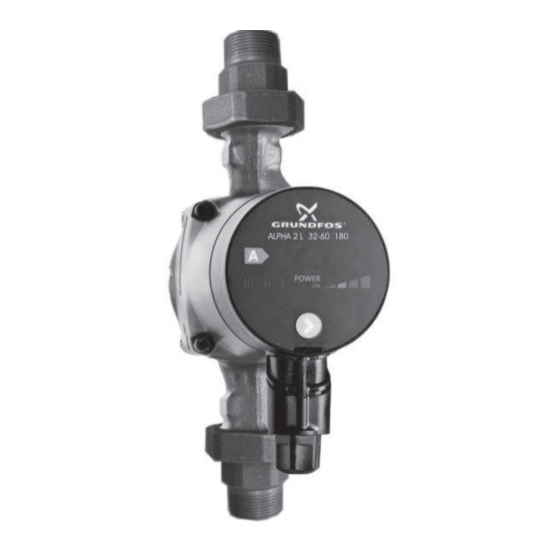
    deutsch Hydraulische Einbindung Die Montage- und Betriebsanleitung des Pumpen- herstellers ist zu beachten! Pumpenverschraubungen von der Pumpe lösen und in die Rohrleitungen eindichten. Wichtig: Die farblich markierte Pumpenverschraubung ist, zur Aufnahme des Thermostats, modifiziert und muss auf der Pumpensaugseite montiert werden.
  • Seite 6: Elektrischer Anschluss

    230V AC F11 4A/T F12 4A/T F13 4A/T F14 4A/T Freigabe prog. Wartung Störung Wärmeerz. Ausgang 1 elektrischer Anschluss (MSR1) der elektrischer Anschluss (MSR2) der Thermostatpumpe bei Einmodulanlagen Thermostatpumpe bei Einmodulanlagen Mehrmodulbetrieb (MSR1) Mehrmodulbetrieb (MSR2) externe Versorgungsspannung Fremdspannung Aktoren extern...
  • Seite 7: Reglereinstellungen

    Reglereinstellungen Die notwendigen Reglereinstellungen zur Thermostatpumpenfunktion sind detailliert in der Bedien- und Einstellanleitung zum MSR1 bzw. MSR2 sowie in der Montageanleitung zum Dachs beschrieben! Isolieren des Pumpengehäuses Über das Pumpengehäuse und die Rohrleitungen geht Wärme verloren. Diese Wärmeverluste sollten durch Isolierung des Pumpengehäuses und der Rohrleitung reduziert werden.
  • Seite 8: General Instructions

    english General Instructions Safety During assembly, commissioning and maintenance the relevant safety regulations must be observed. Safety This symbol is placed in front of all important safety instructions. Follow these in order to prevent danger and damage to persons and material. EC-Conformity and national regulations, directives and standards Our Dachs-products with CE-mark are developed and manufactured pursuant to the current EC-directives effective at the date of inspection.
  • Seite 9: Areas Of Application

    english Areas of application The thermostatic pump is employed mainly in: Single module systems with hot water cylinders where a booster pump is required (e.g. long pipe runs, system separation, heat meters). Multi-module systems with hot water cylinders (up to 3 Dachses per pump thermostat), for feeding the cylinder with hot water at approx.
  • Seite 10 System schematic 3: Multi-module system (up to 3 Dachses) buffer vessel M3 / Module designation M2 / for MSR2: black L1 / for MSR1: grey (Master controller) System schematic 4: Multi-module system (more than 3 Dachses) buffer vessel M6 / M5 / M4 /...
  • Seite 11: Hydraulic Connections

    english Hydraulic connections The pump manufacturer's installation and operating instructions must be observed! Unfasten the couplings from the pump and fit them to the pies. Important: The colour-coded pump coupling has been modi- fied to accept the thermostat and must be fitted on the inlet side of the pump.
  • Seite 12: Electrical Connection

    english Electrical connection The pump manufacturer's installation and operating instructions must be observed! 230V AC X5 2 30V AC F11 4A/T F12 4A/T F13 4A/T F14 4A/T Single systems (MSR 2) black: Controller terminal strip X6/8* X6/6-8 X6/9-10 X6/11-12 X6/3-5 blue: Neutral terminal green/yellow:...
  • Seite 13 Controller Settings The necessary controller settings for thermostatic pump functioning are described in detail in the operating and adjustment manual for the MSR1 and MSR2, as well as in the Dachs installation manual. Isolation of the pump housing Through the pump housing and the piping heat gets lost. This heat losses are to be reduced by isolating the pump housing and the piping.
  • Seite 14: Avvertenze Generali

    itAliAno Avvertenze generali Sicurezza Durante il montaggio, la messa in funzione e la manutenzione attenersi alle disposizioni di sicurezza contenute nelle norme EN, UNI, CEI e ISPESL, ed alle prescrizioni del distribuitore di energia elettrica per l’allacciamento in parallelo alla rete pubblica. Sicurezza Tutte le indicazioni relative alla sicurezza sono contrassegnate da questo simbolo.
  • Seite 15: Campi Di Applicazione

    itAliAno Campi di applicazione La pompa termostatica viene montata in: impianti con modulo singolo con memoria tampone, nel caso si richieda una pompa con pressione all'entrata del regolatore (ad es. grandi impianti di conduzione, interruzione di sistema, contatore quantità di calore). impianti plurimodulari con memoria tampone (fino a 3 Dachs per termostato pompa) rifornire la memoria tampone con ca.
  • Seite 16 Schema di installazione 3: impianto plurimodulare (fino a 3 Dachs) Accumu- latore M3 / Indicazione modulare M2 / per MSR2: nero L1 / per MSR1: grigio (Master) Schema di installazione 4: impianto plurimodulare (più di 3 Dachs) Accumu- latore M6 / M5 / M4 / M3 /...
  • Seite 17 itAliAno Allacciamento idraulico Osservare le Istruzioni per il montaggio e il funzionamento fornite dal produttore delle pompe! Allentare le viti delle pompe e sigillare ermeticamente le tubature. Importante: Al montaggio del termostato la chiusura a vite delle pom- pe, contrassegnata con dei colori, è modificata e deve essere montata sul lato aspirante della pompa.
  • Seite 18: Collegamento Elettrico

    itAliAno Collegamento elettrico Osservare le Istruzioni per il montaggio e il funzionamento fornite dal produttore delle pompe! 230V AC X5 2 30V AC F11 4A/T F12 4A/T F13 4A/T F14 4A/T Impianti singoli (MSR 2) X6/9-10 X6/11-12 X6/3-5 X6/6-8 campo di regolazione X6/8 morsetto d'attacco N ve/gia: morsetto d'attacco PE...
  • Seite 19 Impostazioni del regolatore Le impostazioni necessarie del regolatore per il funzionamento delle pompe termostatiche sono descritte dettagli- atamente nelle Istruzioni di installazione e utilizzo del MSR1 o MSR2 e nelle Istruzioni di montaggio del Dachs! Isolazione del corpo della pompa Attraverso il corpo della pompa e la tubazione va perduto del calore.
  • Seite 20: Indicaciones Generales

    espAÑol Indicaciones generales Seguridad Durante el montaje, la puesta en marcha y el mantenimiento es preciso observar las normativas de se- guridad DIN, DVGW, VDE, TAB y de la UE. Seguridad Este símbolo aparece delante de todas las indicaciones de seguridad importantes. Siga dichas indicaciones para descartar peligros y daños en las personas y bienes materiales.
  • Seite 21: Ámbitos De Aplicación

    espAÑol Ámbitos de aplicación La bomba termostática se emplea en: centrales unimodulares con acumulador intermedio si se precisa un bomba de presión previa (p. ej. grandes longitudes de tuberías, separación de sistemas, contador de cantidades de calor). centrales multimodulares con acumulador intermedio (hasta 3 Dachs por cada termostato de bomba) a fin de alimentar el acumulador intermedio con agua caliente a aprox.
  • Seite 22 Acumulador intermedio M3 / Designación de M2 / módulo para MSR2: negro L1 / para MSR1: gris (Regulador principal) Esquema de la instalación 4: Central multimodular (más de 3 Dachs) Acumulador intermedio M6 / M5 / M4 / M3 / Designación de...
  • Seite 23 espAÑol Integración hidráulica ¡Observar las instrucciones de montaje y uso del fabricante de la bomba! Soltar los racores de la bomba y sellarlos en las tuberías. Importante: El racor de bomba marcado con color está modificado para alojar el termostato y debe montarse en el lado de succión de la bomba.
  • Seite 24: Conexión Eléctrica

    espAÑol Conexión eléctrica ¡Observar las instrucciones de montaje y uso del fabricante de la bomba! 230V AC X5 2 30V AC F11 4A/T F12 4A/T F13 4A/T F14 4A/T Centrales únicas (MSR 2) X6/6-8 X6/9-10 X6/11-12 X6/3-5 negro: Panel de conexiones del regulador X6/8* azul: Borna de conexión N verde/ amarillo: Borna de conexión PE...
  • Seite 25 Ajustes del regulador ¡Los ajustes de regulador requeridos para el funcionamiento de la bomba termostática están descritos al detalle en las instrucciones de manejo y ajuste de la MSR1 o MSR2 así como en las instrucciones de montaje del Dachs! Aislamiento del cuerpo de la bomba A través del cuerpo de la bomba y la tubería sale calor.
  • Seite 26 Dachs - MSR1/MSR2 NOTIZEN: ..........................................................................................................................................................................................................................................................................................................................................................................................................................................................................................................................................
  • Seite 27 Dachs - MSR1/MSR2 NOTIZEN: ..........................................................................................................................................................................................................................................................................................................................................................................................................................................................................................................................................
  • Seite 28 Dachs - MSR1/MSR2 KRAFT - WÄRME - ENERGIESYSTEME C a r l Z e i s s S t r . 9 7 4 2 4 S c h w e i n f u r t F o n :...

Diese Anleitung auch für:

Msr2

Inhaltsverzeichnis