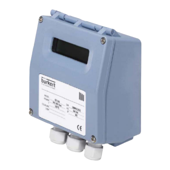
bürkert SE56 Bedienungs- Und Installationsanleitung
Urchfluss-transmitter
Vorschau ausblenden
Andere Handbücher für SE56:
- Bedienungsanleitung (120 Seiten) ,
- Bedienungsanleitung (96 Seiten) ,
- Bedienungsanleitung (125 Seiten)

Verwandte Anleitungen für bürkert SE56


Inhaltszusammenfassung für bürkert SE56
- Seite 37 BEDIENUNGS- UND INSTALLATIONSANLEITUNG Durchfluss-Transmitter SE56 Basic...
- Seite 38 SE 56 INHALTSVERZEICHNIS EINLEITUNG ____________________________________________________ 3 BESTIMMUNGSGEMÄßE VERWENDUNG ________________________________ 3 INBETRIEBNAHME UND WARTUNGSANWEISUNGEN _____________________ 4 IN DIESEM HANDBUCH VERWENDETE SYMBOLE ________________________ 4 GRUNDLEGENDE SICHERHEITSHINWEISE _____________________________ 5 INSTALLATION UND VERKABELUNG __________________________________ 6 TECHNISCHE DATEN ______________________________________________ 7 ELEKTRISCHER ANSCHLUSS ________________________________________ 9 STATUSANZEIGEN UND BEDEUTUNG VON LED-WARNUNGEN ______________ 13 ZUGZNG ZU DEN KONFIGURIERUNGSTASTEN __________________________ 14 ZUGANG ZUM TASTENFELD DES TRANSMITTERS _______________________ 15 AUFRUFEN DER KONFIGURATIONSMENÜS ____________________________ 18...
-
Seite 39: Einleitung
SE 56 EINLEITUNG Dieses Handbuch ist integraler Bestandteil des Geräts. Lesen Sie die hierin enthaltenen Anweisungen sorgfältig durch, da sie wichtige Hinweise zur sicheren Verwendung und zur Wartung enthalten. Unangekündigte Änderungen der technischen Informationen und der in diesem Handbuch behandelten Geräte sind vorbehalten. Der Durchflussmesser muss gemäß... -
Seite 40: Inbetriebnahme Und Wartungsanweisungen
SE 56 INBETRIEBNAME UND WARTUNGSANWEISUNGEN Überprüfen Sie vor der Inbetriebnahme des Geräts Folgendes: Die Versorgungsspannung muss mit der auf dem Typenschild angegebenen Spannung übereinstimmen. Alle Elektroanschlüsse müssen gemäß den Angaben auf Seiten 8-9 ausgeführt werden. Die Erdungsanschlüsse müssen gemäß den Angaben auf Seite 8 ausgeführt ... -
Seite 41: Grundlegende Sicherheitshinweise
SE 56 GRUNDLEGENDE SICHERHEITSHINWEISE Diese Sicherheitshinweise berücksichtigen keine: Zufälligkeiten und Ereignisse, die bei Montage, Betrieb und Wartung der Geräte auftreten können. Ortsbezogene Sicherheitsbestimmungen, für deren Einhaltung, auch in Bezug auf das Installations- und Wartungspersonal, der Betreiber verantwortlich ist. GEFAHR Allgemeine Gefahrensituationen. -
Seite 42: Installation Und Verkabelung
SE 56 INSTALLATION UND VERKABELUNG Verletzungsgefahr bei unsachgemäßer Installation! Fluidische elektrische Installationen dürfen durch autorisiertes Fachpersonal geeignetem Werkzeug durchgeführt werden! Verwenden unbedingt geeignete Sicherheitsvorrichtungen (ordnungsgemäß dimensionierte Sicherungen und/oder Schutzschalter). Beachten Sie die Montageanweisungen des verwendeten Fittings. Verletzungsgefahr durch ungewolltes Einschalten der Anlage und unkontrollierten Wiederanlauf! Anlage vor unbeabsichtigtem Betätigen sichern. -
Seite 43: Technische Daten
SE 56 TECHNISCHE DATEN ELEKTRISCHE DATEN Schutzklasse des Transmitters: Klasse I, IP 65, Anlagenkategorie II Stromversorgungs Versorgungs- Stromfrequenz Max. Leistung versionen spannung Hochspannung 100-240 VAC +/- 10% 44-66 Hz 12-60 VDC +/- 10% Niederspannung 18-45 VAC +/- 10% 44-66 Hz ISOLATION DER EIN-/AUSGÄNGE Die Ein-/Ausgänge sind bis 500 V isoliert. -
Seite 44: Abmessungen
SE 56 ABMESSUNGEN WERKSTOFFE NYLON, Dichtung aus NBR POLYCARBONATE, Dichtung aus NBR NYLON POLYAMIDE, Dichtung aus NBR Hülse aus Messing, Schraube aus Edelstahl AISI 304L POLYAMIDE, Dichtung aus NBR Diese Werkstoffe sind mit der Umbegung in Kontakt. Keiner der Werkstoffe des Geräts sind mit der Flüssigkeit in Kontakt. -
Seite 45: Elektrischer Anschluss
SE 56 ELEKTRISCHER ANSCHLUSS ERDUNGSANWEISUNGEN Damit der Transmitter ordnungsgemäß funktioniert, MÜSSEN Sensor und Flüssigkeit immer das gleiche Potenzial aufweisen. Erden Sie Sensor und Transmitter also IMMER. STROMVERSORGUNG DES TRANSMITTERS Stellen Sie vor dem Anschließen der Stromversorgung unbedingt sicher, dass die Versorgungsspannung in dem auf dem Typenschild angegebenen Bereich liegt. -
Seite 46: Innenansicht Des Transmitters
SE 56 INNENANSICHT DES TRANSMITTERS Stromversorgung IF2: Anschluss für Programmierstecker Anzeige-LED: Bedeutung siehe Seite 12 Gefährliche Spannung an Klemmen 12-13: - 60 Vdc max. - 250 V max. bei Spulenkommutierung (Schalten) Tastenfeld Versorgungsspannung >NS< >HS< 18-45VAC 100-240VAC 12-60VDC ELEKTRISCHER ANSCHLUSS DES SENSORS SPULEN OUT2 OUT1... -
Seite 47: Digitaleingang
SE 56 DIGITALEINGANG Externe Stromversorgung Interne Stromversorgung 10 K 5 (+) 10 K 3/40 Vdc (ON) 0/1,5 Vdc (OFF) 6 (-) BETRIEB BEI EINGANG EIN/AUS Auto-Kalibrierung Tmin < T < 1 s = Autokalibrierung T > 1 s = Auto-Null AUTOCALIB. -
Seite 48: Ausgangsanschluss
SE 56 AUSGANGSANSCHLUSS Digitalausgang Optisch isolierter Ausgang mit potentialfreien 16 (out1) Kollektor- und Emitteranschlüssen, die beliebig 18 (out2) verschaltet werden können. Maximale Schaltspannung: 40 Vdc Maximaler Schaltstrom: 100 mA Maximale Sättigungsspannung zwischen Kollektor und Emitter bei 100 mA: 1,2 V Maximale Schaltfrequenz (Last an Kollektor oder ... -
Seite 49: Statusanzeigen Und Bedeutung Von Led-Warnungen
SE 56 STATUSANZEIGEN UND BEDEUTUNG VON LED-WARNUNGEN STATUSKÜRZEL BEDEUTUNG DES KÜRZELS STATUSKÜRZEL BESCHREIBUNG Max.-Alarm aktiviert Min.-Alarm aktiviert - Unterbrechung Spulenkreis / Signalfehler / Leere Rohrleitung Kalibrierung läuft Simulation Sättigung des Impulsausgangs (reduziert ZEITIMPULS) HINWEIS: Wenn die Summenzählerseiten angezeigt werden, wird rechts die Statusanzeige „!“ sichtbar. BEDEUTUNG DER LED DAUERLEUCHTEN: Initialisierung BLINKLICHT (1 s): Normalbetrieb... -
Seite 50: Zugzng Zu Den Konfigurierungstasten
SE 56 INBETRIEBNAHME ACHTUNG! Verletzungsgefahr bei unsachgemäßer Inbetriebnahme! Nicht sachgemäßer Betrieb kann zu Verletzungen sowie Schäden am Gerät und seiner Umgebung führen. - Vor der Inbetriebnahme muss gewährleistet sein, dass der Inhalt der Bedienungsanleitung dem Bedienungspersonal bekannt ist und vollständig verstanden wurde. -
Seite 51: Zugang Zum Tastenfeld Des Transmitters
SE 56 ZUGANG ZUM TASTENFELD DES TRANSMITTERS Das Tastenfeld ist nach Lösen der 4 Schrauben der Abdeckung und Öffnen der Frontabdeckung des Transmitters zugänglich. Neben der Klemmleiste der Stromversorgung befinden sich drei TASTEN, mit denen der Benutzer angezeigte Daten und KEYBOARD Funktionen auswählen kann. -
Seite 52: Aufrufen Der Transmitter-Funktionen Beim Starten (Einschalten) )
SE 56 AUFRUFEN DER TRANSMITTER-FUNKTIONEN BEIM STARTEN (Einschalten) ) Beispiel der beim Starten angezeigten Seiten Wird der Transmitter direkter Sonneneinstrahlung ausgesetzt, kann die Flüssigkristallanzeige (LCD) beschädigt werden. Hinweis: Beim Einschalten des Transmitters erscheint die links dargestellte Anzeige. Aktive Skala Verwenden Sie die Tasten des * Direkte/umgekehrte Tastenfelds wie in der Mitte Summenzähleranzeige... - Seite 53 SE 56 DURCHFLUSSANZEIGE Mit dem ML110 kann eine 5-stellige Digitalanzeige der Durchflusseinheiten angezeigt werden. Dies bedeutet, dass der maximale Durchflusswert, der auf dem Display angezeigt werden kann, 19999 beträgt (unabhängig Kommaposition), und das Minimum 0,025. Die Berechnung des Transmitters basiert auf der folgenden Formel: DN x DN x 0,008 Die Ergebnisse der obigen Berechnung ergeben den maximalen Durchfluss bei 10m/s Geschwindigkeit gemäß...
-
Seite 54: Zugangscodes Für Die Einstellung Der Transmitter-Funktion
SE 56 ZUGANGSCODES FÜR DIE EINSTELLUNG DER TRANSMITTER-FUNKTION Werkseitig voreingestellte Zugangscodes Benutzerdefinierte Zugangscodes Der Transmitter wird mit dem Standard- Funktionen im „Hauptmenü“ des Transmitters Zugangscode für L2 (Level 2) ausgeliefert. werden durch die Zugangscodes aktiviert. Die Der Code ist für den Aufruf der Informationen in diesem Handbuch beziehen „Hauptmenü“-Funktionen vom sich auf alle Funktionen, die in Zugangsstufe L2... - Seite 55 SE 56 BEISPIEL: „Quickstartmenü“ Funktionsänderung. Skalenendwert 1 (Fs1) von 4 dm³/s auf 5 dm³/s. Rufen Sie das Rufen Sie die „Quickstartmenü“ auf. Funktion „Fs1“ durch Die bei jedem Schritt zu kurzes (< 1 s) drückende Taste wird durch Drücken der das Symbol vor einer der angegebenen Taste drei Tasten des Tastenfelds...
- Seite 56 SE 56 BEISPIEL: „Hauptmenü“ Funktionsänderung. Skalenendwert 1 (Fs1) von 4 dm³/s auf 5 dm³/s. (Quickstartmenü aktiviert) Drücken Sie die Rufen Sie das Rufen Sie das angegebene „Quickstartmenü“ „Hauptmenü“ durch Taste, um von der auf. Drücken der Quickmenüseite Von irgendeiner der angegebenen Taste Startseiten Hauptmenüseite...
-
Seite 57: Hauptmenügruppen Und Funktionsbeschreibungen
SE 56 HAUPTMENÜGRUPPEN UND FUNKTIONSBESCHREIBUNGEN. Das Hauptmenü wird im Quickstartmenü ausgewählt, indem die Taste gedrückt und der werkseitige Code (11111) eingegeben wird. Grau dargestellte Funktionen werden nur mit anderen Funktionen (Einzelheiten zu den Funktionen mit dem Symbol „*” finden Sie angezeigt, oder mit optionalen Modulen. - Seite 58 SE 56 4.1 Prozentsatz des max. Direktdurchflusses, bei der ein Alarm erzeugt wird 4.2 Prozentsatz des max. Umkehrdurchflusses, bei der ein Alarm erzeugt wird 4.3 Hysteresegrenze für den Alarm bei minimalem und maximalem Durchfluss 4.1 Maximum flow rate value alarm setting 4.5*Stromausgangswert bei Störung (Funktionsinfo und Änderung Seite 24) 4.2 Minimum flow rate value alarm setting 4.6*Frequenzausgangswert bei Störung (Funktionsinfo und Änderung Seite 25)
- Seite 59 SE 56 10.1* Kalibrierung des Konverters (einmalig bei jeder Auswahl der Funktion) 10.2* Autotest des Konverters (einmalig bei jeder Auswahl der Funktion) 10.3* Aktivieren der Durchflusssimulation 10.1* Calibration of the converter (single occurrence each time function is selected) 10.4 Service-Funktionen: erfordert L3-Code 10.2* Converter auto test (single occurrence each time function is selected) 10.5 Service-Funktionen: erfordert L3-Code 10.3* Flow rate simulation enabling...
-
Seite 60: Programmierung Der Hauptmenü-Funktionen
SE 56 PROGRAMMIERUNG DER HAUPTMENÜ-FUNKTIONEN (Beschreibung der Funktionen mit einem Zugangscode < 3; Hinweis: die Funktionen der Stufe 3 sind dem Service vorbehalten) Identifikation der Funktion (nicht auf dem Display MENÜ 1 - SENSOR (POS. 1) Nenndurchmesser des Sensors [ND= XXXX] Transmitteranforderung Auf dem Transmitter angezeigtes Menü... - Seite 61 SE 56 Unterscheidung zwischen den britischen und den amerikanischen Einheiten erfolgt durch Groß- und Kleinbuchstaben. Cubic inch Ounce Kubikzentimeter American gallon Pound Milliliter British gallon Short tons Liter Cubic foot Kubikdezimeter Standard barrel Dekaliter Gramm Oil barrel Hektoliter Kg Kilogramm Cubic yard Kubikmeter Tonne...
-
Seite 62: (Pos. 4.5) Stromausgangswert Bei Störung
SE 56 des Geräts in zwei Fällen: Zuerst wird eine Schwankung des Durchflusses von 0 bis 10 % vollständig vom Effekt der Zeitkonstanten kompensiert. Im zweiten Fall wird eine Schwankung von 10 % bis 100 %, die die Beschleunigungsgrenze überschreitet, sofort an den Ausgang gesendet. - Seite 63 SE 56 Wert amerikanischen Maßeinheiten beträgt damit folgenden Diagnosefunktionen ermöglicht: Strom < 2 mA - 5 %: Leitung unterbrochen, Ausfall der Stromversorgung oder defekter Transmitter; 2 mA -5 % ≤ Strom ≤ 2 mA + 5 %: Hardware-Alarm; ...
-
Seite 64: (Pos. 6.3) Einschaltdauer Für Impulse/Frequenzausgang
SE 56 (POS. 6.3) Einschaltdauer für Impulse/Frequenzausgang [Duty cycle=% XX] [OUT.1=XXXXXX] Die Einschaltdauer definiert das Zeitverhältnis zwischen An- und Abschaltung bei Verwendung von Frequenzausgängen: 50 % bedeutet, dass die AN-Phase gleich lang ist wie die AUS-Phase. 60 % bedeutet, dass die AN-Phase 60 % und die AUS-Phase 40 % der Gesamtzeit ausmachen. Wenn Impulsausgänge verwendet werden, definiert die Einschaltdauer nur die AUS-Phase, da die AN-Phase bereits mit der Funktion „IMPULSDAUER“... -
Seite 65: (Pos. 8.7-8.8-8.9-8.10) Summenzähler/Teilzähler - Rücksetzen Aktivieren [T/P/-/+ Reset]
SE 56 MENÜ 8 - ANZEIGE (POS. 8.5) Summenzähler-Änderung aktivieren [Tot.modif.=ON/OFF] Aktivieren Sie diese Funktion, um den Summenzähler zu ändern. Gehen Sie, ausgehend von den Anzeigeseiten, wie folgt vor: 1) Drücken Sie die Taste , stellen Sie den L2-CODE ein, falls erforderlich (andernfalls weiter bei Schritt 2) und drücken Sie dann die Taste 2) Positionieren Sie den Cursor mit der Taste auf dem zu ändernden Zahlenwert, drücken Sie die... -
Seite 66: Alarmmeldungen, Ursachen Und Gegenmassnahmen Wartung Und Fehlerbehebung
SE 56 ALARMMELDUNGEN, URSACHEN UND GEGENMASSNAHMEN WARTUNG UND FEHLERBEHEBUNG Sicherheitshinweise GEFAHR! Verletzungsgefahr durch hohen Druck in der Anlage! - Vor dem Lösen der Prozessanschlüsse die Flüssigkeitszirkulation stoppen und den Druck ablassen. Verletzungsgefahr durch Stromschlag ! - Schalten Sie vor Beginn der Arbeiten in jedem Fall die Spannung ab und sichern Sie diese vor Wiedereinschalten! - Beachten Sie geltende Unfallverhütungs- und Sicherheitsbestimmungen für elektrische Geräte. -
Seite 67: Fehlercodes
SE 56 FEHLERCODES CODES STÖRUNGSBESCHREIBUNG DURCHZUFÜHRENDE MASSNAHME 0001 Problem mit der Überwachungsschaltung 0002 Falsch konfigurierte Arbeitsdaten im EEPROM 0004 Falsch konfigurierte Sicherheitsdaten im EEPROM 0008 Defektes EEPROM Defekte Tastatur (eine oder mehrere Tasten beim 0010 Test gedrückt) MELDUNG BEIM KUNDENDIENST Versorgungsspannung (+3,3) außerhalb des zul. -
Seite 68: Konformitätserklärung
SE 56 KONFORMITÄTSERKLÄRUNG erklärt in eigener Verantwortung, dass das Produkt Modell Konverter SE 56 Modell Sensoren: S051 – S054 – S055 – S056 auf das sich diese Erklärung bezieht, konform ist zu den folgenden harmonisierten Europäischen Normen: CEI EN 61010-1 (2001) ... - Seite 69 SE 56...
- Seite 70 SE 56...
- Seite 71 SE 56...
- Seite 72 110_DE_BU_3_3_6X.doc Die Versionsnummer dieses Handbuch wird durch die vierte Nummer von Rechts angegeben. Die letzten drei Zeichen des Dateinamens identifizieren die Software- Version, auf die sich dieses Handbuch bezieht. Die Software-Version des Transmitters wird während des Einschaltens angezeigt.