Herunterladen Inhalt Inhalt Diese Seite drucken
bürkert SE 56 Bedienungsanleitung
Vorschau ausblenden Andere Handbücher für SE 56:
Inhaltsverzeichnis

Werbung

Verfügbare Sprachen

Verfügbare Sprachen

INSTRUCTION MANUAL
TRANSMITTER WITH DISPLAY
SE 56
Version Jun2009/01

Werbung

Inhaltsverzeichnis
loading

Inhaltszusammenfassung für bürkert SE 56

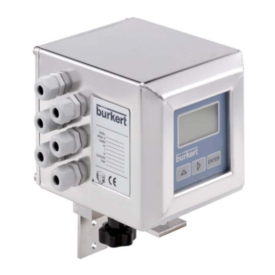
  • Seite 1 INSTRUCTION MANUAL TRANSMITTER WITH DISPLAY SE 56 Version Jun2009/01...
  • Seite 2: Inhaltsverzeichnis

    SE 56 TABLE OF CONTENTS Introduction ___________________________________________p.3 Symbol Used on the manual ________________________________________ p.3 Technical characteristics ________________________________p.4 Electrical characteristics ___________________________________________ p.4 Environmental conditions of use _____________________________________ p.4 Operating temperature_____________________________________________ p.4 Overall dimensions _______________________________________________ p.5 Grounding instructions _____________________________________________ p.6 Transmitter power supply___________________________________________ p.6 Electrical connections _____________________________________________ p.
  • Seite 3: Introduction

    SE 56 INTRODUCTION This manual is integral part of the product. Read carefully the instructions contained since they give important indications for the safe use and maintenance. Technical information and relative products in this manual could undergo modifications without any previous notice.
  • Seite 4: Technical Characteristics

    SE 56 TECHNICAL CHARACTERISTICS ELECTRIC CHARACTERISTICS Classification of the instrument: class I, IP 67, category of installation II Power supply Power supply Power supply Current Pmax versions voltage frequency 90÷265 Vac 44÷66 Hz 20W/25VA 0,25 A 18÷45 Vac/dc 0-44÷66 Hz...
  • Seite 5: Overall Dimensions

    SE 56 OVERALL DIMENSIONS COMPACT VERSION WALL-MOUNTED VERSION PANEL-MOUNTED VERSION IP65 (OPTIONAL)
  • Seite 6: Grounding Instructions

    SE 56 Grounding instructions For the correct operation of the transmitter is NECESSARY that sensor and liquid are equipotential, so ALWAYS connect sensor and transmitter to the ground TRANSMITTER POWER SUPPLY Wall-mounted Before connecting the power supply, verify that version...
  • Seite 7: Electrical Connections

    SE 56 ELECTRICAL CONNECTIONS TERMINAL BLOCK M1 FOR COMPACT AND WALL-MOUNTED VERSIONS Power supply IF2 socket LOCK 2 3 4 5 6 7 8 9 10 Signalling LED: interpretation at page 18 11 12 13 14 15 16 17 18 19 20...
  • Seite 8 SE 56 ELECTRICAL CONNECTIONS SENSOR TO TRANSMITTER TERMINAL BLOCK M1 WALL-MOUNTED VERSION ELECTRODES INPUT RS485 4-20mA 9 10 11 12 13 14 15 16 17 18 19 20 Sudden movements of the electrodes COILS OUT1 OUT2 cable, can cause noises on measure.
  • Seite 9: Inputs/Outputs

    SE 56 INPUTS/OUTPUTS (BLOCK M2) LEGEND OPTIONAL MODULES (relay modules at next page) SC: Cable shield, electrically connected to ground and to the casing 2 programmable on/off outputs + 1 on/off input CTS: Input terminal of the signal “CLEAR TO SEND” of the RS232 port...
  • Seite 10: Optional Relay Modules

    SE 56 INPUTS/OUTPUTS (BLOCK M2) CONT’D LEGEND OPTIONAL RELAY MODULES SC: Cable shield, electrically 2 relay outputs with 1 NO contact + 1 connected to ground and to the NC contact each, 2A 60Vac, casing 60W/125Va C: relay – common...
  • Seite 11: Input

    SE 56 INPUT External power supply Internal power supply 10 K 5 (+) 10 K 3/40 Vdc (ON) 0/1,5 Vdc (OFF) 6 (-) The functions referring to the inputs can be divided in three groups: Functions only assignable to the input 1 (page 12)
  • Seite 12 SE 56 OPERATION ON INPUT ON/OFF INPUT OPERATION STAGE (GENERIC FUNCTIONS) Auto-calibration Tmin<T<1sec. = autocalibration T > 1 sec. = Auto zero AUTOCALIB. OFF Necessary conditions for enabling the function 3-40 V POS. 5.7 ON POS. 5.9 (batch on input 1) OFF 0-1,5 V POS.
  • Seite 13 SE 56 OPERATION STAGE ON INPUT 1 OR 2 (BATCH FUNCTION) Start batch from remote input Necessary conditions for enabling the 3-40 V function 0-1,5 V POS. 5.9 ON or POS. 5.10 on “Batch” Opening Closing valve valve POS. 6.1 ÷ 6.4 on “end batch”...
  • Seite 14 SE 56 OPERATION STAGE ON INPUT 1 AND 2 (BATCH FUNCTION) Start batch on remote input 1 Stop from output selection formula 00 or Necessary conditions for enabling the function 01 from remote input 2 Start 3-40 V 0-1,5 V POS.
  • Seite 15 SE 56 OUTPUTS WIRING Output on/off 1250 Hz Opto-insulated output with collector and emitter 16 (out1) terminals floating and freely connectable 18 (out2) Maximum switching voltage: 40 Vdc Maximum switching current: 100mA Maximum saturation voltage between collector and emitter at 100mA: 1,2V Maximum switching frequency (load on the collector or emitter, RL=470Ω, VOUT=24Vdc): 1250Hz...
  • Seite 16: Start Up And Maintenance Of The Devices

    SE 56 START UP AND MAINTENANCE OF THE DEVICES Before starting up the device please verify the following: Power supply voltage must correspond to that specified in the name plate Electric connections must be done as described at page 8...
  • Seite 17: Transmitter Visualization

    SE 56 VISUALIZATION PAGES The direct exposure of the trasnmitter to the solar rays, could damage the liquid crystals display. N.B. Contrast set see page 32 pos. 8.3 Flow rate value Analogical bar of flow rate variations % full scale...
  • Seite 18: Flags Interpretation And Led

    SE 56 Flags and LED interpretation FLAGS INTERPRETATION OF THE FLAGS FLAG DESCRIPTION Alarm max activated Alarm min activated - Interruption coils circuit - Signal error - Empty pipe Calibration running Simulation Pulse output saturation (reduce TIME PULSE ) LOCK...
  • Seite 19 SE 56 KEYBOARD SHORT PRESS (< 1 SECOND): Increases the digital value or the parameter selected by the cursor Goes to the previous menu position Batch start/stop (when enabled) LONG PRESS (> 1 SECOND): Decreases the digital value or the parameter selected by the cursor Goes to the next menu position SHORT PRESS (<...
  • Seite 20 SE 56 MENU Some of the most used functions can be accessed directly using the “Quick start menu” by pressing the “ENTER” key. The Quick start menu can be disabled by the function 8.6 in the display menu: if the Quick start menu is disabled, pressing the “ENTER” key gives access to the main menu.
  • Seite 21 SE 56 SE56 Functions (functions with symbol “*” are detailed at page 27 and following) Attention : The functions in grey are visualized on the display only with other active functions or with optional modules Enter the Nominal Diameter on sensor label (0-3000 mm)
  • Seite 22 SE 56 5.1* Total direct (positive) flow totaliser reset enabling 5.2* Partial direct (positive) flow totaliser reset enabling 5.3* Total reverse (negative) flow totaliser reset enabling 5.4* Partial reverse (negative) flow totaliser reset enabling Reset above totalisers set to “ON”, through pulse from input 1 (see page 12) Totaliser counting lock command (see page 12) 5.7*...
  • Seite 23 SE 56 9.1* Date and time set Automatic data logger enable Interval time for the data logging function: 1, 2, 3, 6, 8, 12, 24, 48 hours Displaying of the data stored in the data logger Displaying of the last 64 alarms stored in the data logger...
  • Seite 24: Access The Configuration Menus

    SE 56 ACCESS TO THE CONFIGURATION MENUS The access to the configuration menu can take place in two different modes: The “Quick start menu” allows direct access to some of the principal functions The “Main menu” allows access to all the functions with access code ≤ 2 We show below some examples relating to the change of the value in the “Fs1”...
  • Seite 25 SE 56 EXAMPLE: modifying the full scale value from 4 dm³/s to 5 dm³/s From the “Main Menu” (quick start menu enabled) Enter in the Access to the “Main “Quick start menu” Menu” 5 TIMES Press Access to the Access to the function repeatedly “Scales”...
  • Seite 26: Access Codes

    SE 56 ACCESS CODES FACTORY PRE-SETTINGS ACCESS CODES Some functions in the transmitter are enabled by the access codes. The information within this manual is related to all The transmitter is delivered with access the functions available with L2 level. All the...
  • Seite 27: Functions Description

    SE 56 FUNCTIONS DESCRIPTION (description of the functions with access code < 3) Identification of the function (not visualized on display) MENU 1.SENSOR (POS. 1) Nominal diameter of sensor [ND= XXXX] Transmitter Menu visualized on the transmitter ( from 1 to Synthetic description of the function N.B.: only some functions of the transmitter are detailed hereafter...
  • Seite 28 SE 56 Available units of mass and volume: Cubic centimetre Cubic inch Gram Millilitre American gallon Kilogram Liter British gallon Cubic decimeter Cubic foot Decalitre Standard barrel Ounce Hectolitre Oil barrel Pound Cubic metre Cubic yard short tons KAmerican gallon...
  • Seite 29 SE 56 (POS. 3.4) Peak cut off threshold [PEAK THR=% XXX] Anomalous signal peak cut off threshold set. This parameter allows setting the maximum value of deviation of the actual measure sample by comparison with the average one. If the new value is higher than the set limit, than such a value is “cut”...
  • Seite 30 SE 56 N.B.: Setting this parameter to zero corresponds to disable the alarm (POS. 4.8) Frequency output value in case of failure [Hz VAL.FAULT=%XXX] Setting of the frequency value to assign to the on/off output in one or more of the following cases: Empty pipe ;...
  • Seite 31 SE 56 MENU 6.OUTPUT (POS. 6.1-6.2-6.3-6.4) Function corresponding to on/off outputs 1-2-3-4 [OUT1=XXXXXX] To choose the function associated to digital Output 1. The functions are listed in the table below. The outputs 3-4 are optional, furthermore output 4 is the only output, which can reach a 12.5 KHz frequency.
  • Seite 32 SE 56 (POS. 6.6-6.7) Function and range of current output n.1-2 [OUT.mA1-2=X÷XX±] To choose the function and the range of current output N.1-2. The current output N.1 is optional and is mounted on the main board. There are three fields to modify this function: Scale zero: 4 or 0 mA ;...
  • Seite 33 SE 56 MENU 8.DISPLAY (POS. 8.3) Display contrast set [CONTRAST=X] Display visual contrast set. The contrast can change according to the room temperature. The set values are from 0 to 15. The entered value has effect only when leaving the function itself.
  • Seite 34 SE 56 MENU 12.BATCH Menu visualized if with batch feature active (output on batch and/or pos. 5.9 enabled or 5.10 on batch) (POS. 12.1) Number of batch samples [N.SAMPLES=XXX] Number of batch cycles to be done to define the value of compensation. This function allows to automatically determine the average value for automatic compensation of system delay (POS.
  • Seite 35: Batch

    SE 56 BATCH FUNCTION ENABLE BATCH Enable one of the following functions to enable and program the batch on the transmitter: POS. 5.9-5.10: START/STOP batch from input POS. 6.1-6.2: assign one of the functions to one of the two outputs Some examples of operation of such functions are visualized at page 11 and following.
  • Seite 36: Start Stop Batch

    SE 56 START STOP BATCH START: it is possible to activate the start of batch in two different ways: from a remote input: assigning the functions of start/stop batch to input 1 (POS. 5.9) or input 2 (POS. 5.10) and using the input/s like visualized at page 12 and following.
  • Seite 37: Alarm Messages

    SE 56 Alarm messages, causes and actions to be taken Messages ANOMALIES ACTION TO TAKE NO ALARMS All works regularly ----- Check the maximum flow rate threshold set and the MAX ALARM The flow rate is higher than the maximum threshold set...
  • Seite 38: Appendix 1

    SE 56 APPENDIX 1 Display rotation Fixing screw Pic.4 of board Pic.5 Pic.1 Display Rotate the display in the desired position, Unscrew the screws suitable in pic. 1 ensure the seal is correctly fitted and the contact surfaces are clean, then insert the display in the lodging.
  • Seite 39: Declaration Of Conformity

    SE 56 DECLARATION OF CONFORMITY declares under the own responsibility that the product Model transmitter SE 56 Model sensors: S051 – S054 – S055 – S056 to which this declaration refers, is in compliance with the following Harmonized European Norms:...
  • Seite 40 SE 56...
  • Seite 41 MANUEL D’UTILISATION TRANSMETTEUR DE DEBIT AVEC AFFICHEUR SE 56 Version Jun2009/01...
  • Seite 42 SE 56 Table des matières Introduction __________________________________________ p. 3 Symboles utilisés dans le manuel ____________________________________ p. 3 Caractéristiques techniques ____________________________ p. 4 Caractéristiques électriques_________________________________________ p. 4 Conditions ambiantes d'utilisation ____________________________________ p. 4 Température de fonctionnement _____________________________________ p. 4 Dimensions générales _____________________________________________ p.5 Instructions de mise à...
  • Seite 43: Introduction

    SE 56 INTRODUCTION Le présent manuel fait partie intégrante du produit. Lisez attentivement les instructions qu’il contient car elles donnent des indications importantes pour une utilisation et un entretien en toute sécurité. Les informations techniques et produits correspondants du manuel peuvent être modifiées sans avertissement préalable.
  • Seite 44: Caractéristiques Techniques

    SE 56 CARACTÉRISTIQUES TECHNIQUES CARACTÉRISTIQUES ÉLECTRIQUES Classification de l’appareil : classe I, IP 67, catégorie d’installation II Type Tension Fréquence du Courant Pmax d’alimentation d’alimentation secteur max. 90÷265 Vac 44÷66 Hz 20W/25VA 0,25 A 18÷45 Vac/dc 0-44÷66 Hz 20W/25VA 1,6 A 10÷35 Vdc...
  • Seite 45: Dimensions Générales

    SE 56 DIMENSIONS GÉNÉRALES VERSION COMPACTE VERSION A MONTAGE MURAL VERSION ENCASTRABLE IP65 (OPTIONAL)
  • Seite 46: Instructions De Mise À La Terre

    SE 56 Instructions de mise à la terre Pour le bon fonctionnment du transmetteur, il est nécessaire que le capteur et le fluide aient le même potentiel : reliez toujours le capteur et le transmetteur à la même terre. ALIMENTATION DU TRANSMETTEUR Version à...
  • Seite 47: Branchements Électriques

    SE 56 BRANCHEMENTS ELECTRIQUES BORNIER M1 POUR LES VERSIONS COMPACTES ET À MONTAGE MURAL Alimentation électrique Port IF2 LOCK 2 3 4 5 6 7 8 9 10 Voyant de signalisation: interprétation page 18 11 12 13 14 15 16 17 18 19 20 Commutateur DIP pour activer les niveaux d’accès...
  • Seite 48 SE 56 BRANCHEMENTS ÉLECTRIQUES RACCORD-CAPTEUR ET TRANSMETTEUR VERSION À MONTAGE BORNIER M1 MURAL ÉLECTRODES ENTRÉE RS485 4-20mA 9 10 11 12 13 14 15 16 17 18 19 20 Des mouvements brusques du câble des BOBINES OUT 1 OUT 2 électrodes peuvent provoquer des bruits...
  • Seite 49: Entrées/Sorties

    SE 56 ENTRÉES/SORTIES (BLOC M2) LÉGENDE MODULES EN OPTION (modules relais page suivante) SC : blindage de câble, branché électriquement à la terre et au boîtier 2 sorties on/off programmables + 1 entrée on/off CTS : borne d’entrée du signal « PRÊT À...
  • Seite 50: Modules Relais En Option

    SE 56 ENTRÉES/SORTIES (BLOC M2) (suite) LÉGENDE MODULES RELAIS EN OPTION SC : blindage de câble, branché 2 sorties relais avec 1 contact NO électriquement à la terre et au boîtier (normalement ouvert) + 1 contact NC (normalement fermé) C : relais – commun chacune, 2A 60Vac, 60W/125Va NC : contact normalement fermé...
  • Seite 51: Entrée

    SE 56 ENTRÉE Alimentation électrique Alimentation électrique externe interne 10 K 5 (+) 10 K 3/40 Vdc (ON) 0/1,5 Vdc (OFF) 6 (-) Les fonctions faisant référence aux entrées peuvent être divisées en trois groupes : fonctions uniquement attribuables à l’entrée 1 (page 12) fonctions agissant directement sur les entrées indépendamment de l’entrée...
  • Seite 52 SE 56 FONCTIONNEMENT DE L’ENTRÉE ON/OFF FONCTIONS GÉNÉRIQUES Calibration automatique Tmin<T<1sec. = calibration automatique T > 1 sec. = auto-zéro AUTOCALIB. OFF Conditions nécessaires pour activer la fonction 3-40 V POS. 5.7 ACTIVÉE POS. 5.9 (dosage à l’entrée 1) DÉSACTIVÉE 0-1,5 V POS.
  • Seite 53 SE 56 FONCTIONNEMENT DE L’ENTRÉE 1 OU 2 (FONCTION DOSAGE) Démarrer dosage à partir de l’entrée distante Conditions nécessaires pour activer la 3-40 V fonction 0-1,5 V POS. 5.9 ACTIVÉE ou POS. 5.10 réglée sur « dosage » Ouverture Fermeture...
  • Seite 54 SE 56 FONCTIONNEMENT DES ENTRÉES 1 et 2 (FONCTION DOSAGE) Démarrer dosage sur l’entrée distante 1 Arrêt à partir de la sortie sélection des formules Conditions nécessaires pour activer la 00 ou 01 à partir de l’entrée distante 2 fonction Début...
  • Seite 55 SE 56 CÂBLAGE DES SORTIES Sortie on/off 1250 Hz Sortie opto-isolée avec bornes flottantes de collecteur 16 (out1) et émetteur pouvant être connectées librement 18 (out2) Tension de commutation maximale : 40 Vdc Courant d’interruption maximal: 100mA Tension de saturation maximale entre le collecteur et l’émetteur à...
  • Seite 56: Démarrage Et Entretien Des Appareils

    SE 56 DÉMARRAGE ET ENTRETIEN DES APPAREILS Avant de démarrer l’appareil, vérifier que : La tension d’alimentation correspond à celle indiquée sur la plaque d’identification Les branchements électriques sont réalisés comme décrit à la page 8 Les connexions de masse sont réalisées Vérifier périodiquement :...
  • Seite 57: Pages De Visualisation Du Transmetteur

    SE 56 PAGES DE VISUALISATION L’exposition directe du transmetteur aux rayons du soleil risque d’endommager l’affichage à cristaux liquides. N.B. Réglage du contraste voir page 33 pos. 8.3 Valeur de débit Barre analog. des variations de débit % pleine échelle Direction du débit...
  • Seite 58: Interprétation Des Indicateurs Et Du Voyant

    SE 56 Interprétation des indicateurs et du voyant INDICATEURS INTERPRÉTATION DES INDICATEURS INDICATEUR DESCRIPTION Alarme max activée Alarme min activée - Circuit bobine interrompu - Erreur de signal - Tuyau vide Calibration en cours Simulation Saturation de la sortie impulsion (réduire DURÉE D’IMPULSION)
  • Seite 59 SE 56 CLAVIER APPUI BREF (< 1 SECONDE): Augmente la valeur numérique ou le paramètre sélectionné par le curseur Accède à la position de menu précédente Démarrage/arrêt du dosage (si activé) APPUI LONG (> 1 SECONDE): Diminue la valeur numérique ou le paramètre sélectionné par le curseur Accède à...
  • Seite 60 SE 56 MENU Il est possible d’accéder directement à certaines des fonctions les plus utilisées à l’aide du menu «QUICKSTART» (Démarrage rapide) en appuyant sur la touche «ENTER». Ce menu peut être désactivé au moyen de la fonction 8.6 du menu affichage : si le menu Quickstart est désactivé, appuyez sur «ENTER»...
  • Seite 61 SE 56 Fonctions du SE 56 (les fonctions suivies de l’astérisque sont détaillées à partir de la page 27) Attention : les fonctions grisées apparaissent uniquement à l'écran si d'autres fonctions sont actives ou si le module optionnel associé est équipé.
  • Seite 62 SE 56 5.1* Autoriser réinit. totalisateur du débit direct total (positif) 5.2* Autoriser réinit. totalisateur du débit direct partiel (positif) 5.3* Autoriser réinit. totalisateur du débit inverse total (négatif) 5.4* Autoriser réinit. totalisateur du débit inverse partiel (négatif) Réinitialiser totalisateur interne d’impulsions à partir de l’entrée 1 Commande verr.
  • Seite 63 SE 56 9.1* Régler la date et l’heure Enregistreur de données (data logger) automatique activé Intervalle pour la fonction enregistrement des données : 1, 2, 3, 6, 8, 12, 24, 48 heures Affichage des données enregistrées dans l’enregistreur de données Affichage des 64 dernières alarmes stockées dans l’enregistreur de données...
  • Seite 64: Accès Aux Menus De Configuration

    SE 56 ACCÈS AUX MENUS DE CONFIGURATION L'accès au menu de configuration peut se faire de deux manières : Par le menu Quickstart permettant d’accéder directement à certaines fonctions principales Par le menu principal permettant d’accéder à l’ensemble des fonctions avec un code d’accès ≤...
  • Seite 65 SE 56 EXEMPLE : modification de la valeur pleine échelle de 4dm³/s à 5dm³/s à partir du menu principal (menu Quickstart activé) Accéder au menu Accéder au menu principal Quickstart 5 FOIS Appuyer Accéder au menu Accéder à la fonction « Fs1 »...
  • Seite 66: Codes D'accès

    SE 56 CODES D’ACCÈS PRÉRÉGLAGE USINE DU CODE D’ACCÈS Certaines fonctions du transmetteur sont activées à l’aide des codes d’accès. Les informations du présent manuel ont trait à Le transmetteur est fourni avec un code toutes les fonctions proposées au niveau L2.
  • Seite 67: Description Des Fonctions

    SE 56 DESCRIPTION DES FONCTIONS (Description des fonctions avec niveau d’accès < 3) Identification de la fonction (pas visualisé à l’écran) MENU 1. CAPTEUR (POS. 1) DN du capteur [ND= XXXX] Invitation à saisie Menu visualisé sur le transmetteur (de 1 à 11) Description succincte de la fonction N.B.: seules quelques fonctions sont détaillées ci-après...
  • Seite 68 SE 56 Unités de masse et de volume disponibles : Centimètre cube Pouce cube Gramme Millilitre Gallon américain Kilogramme Litre Gallon britannique Tonne Décimètre cube Pied cube Décalitre Baril standard Once Hectolitre Baril de pétrole Livre Mètre cube Yard cube Tonne kGallon américain...
  • Seite 69 SE 56 constante de temps et une variation de 10 à 100 % dépassant le seuil d'accélération et envoyée ensuite directement à la sortie. En fait, il existe toujours une durée minimale entre l'acquisition de la mesure et la mise à jour des sorties.
  • Seite 70 SE 56 sorte que, dans les cas susmentionnés, la valeur du courant soit de 2 mA, permettant les diagnostics suivants : courant < 2 mA moins 5%: ligne interrompue, alimentation ou transmetteur défectueux ; 2 mA moins 5% ≤ courant ≤ 2 mA plus 5%: alarme liée au matériel ;...
  • Seite 71 SE 56 (POS. 5.10) Fonctions assignées à l’entrée 2 [ING.2=XXXXXX] Permet de choisir la fonction à associer à l'entrée 2. Les fonctions sont répertoriées dans le tableau suivant. FONCTIONS POUR L’ENTRÉE 2 OFF : DÉSACTIVÉ T+ RESET: RÉINITIALISER TOTALISATEUR DE L’ÉCOULEMENT DIRECT TOTAL (+) P+ RESET: RÉINITIALISER TOTALISATEUR DE L’ÉCOULEMENT DIRECT PARTIEL (+)
  • Seite 72 SE 56 (POS. 6.6-6.7) Fonction et plage du débit de courant n°1-2 [OUT.mA1-2=X÷XX±] Permet de choisir la fonction et la plage du débit de courant n°1-2. Le débit de courant n°1 est en option et monté sur la carte mère. Trois champs permettent de modifier cette fonction : Point zéro : 4 ou 0 mA ;...
  • Seite 73 SE 56 MENU 8. AFFICHAGE (POS. 8.3) Réglage du contraste [CONTRAST=X] Configuration du contraste de l’affichage. Il peut changer en fonction de la température de la pièce. Les valeurs définies sont comprises entre 0 et 15. La valeur saisie est appliquée dès que vous quittez la fonction.
  • Seite 74 SE 56 MENU 12. DOSAGE Menu visualisé uniquement si la fonction dosage est active (sortie réglée sur «dosage» et/ou pos. 5.9 activée ou 5.10 réglée sur «dosage») (POS. 12.1) Nombre d’échantillons de dosage [N.SAMPLES=XXX] Nombre de cycles de dosage nécessaires pour définir la valeur de compensation. Cette fonction permet de déterminer automatiquement la valeur moyenne de la compensation automatique du retard...
  • Seite 75: Dosage

    SE 56 FONCTION DE DOSAGE ACTIVER LE DOSAGE L’une des fonctions suivantes permet d’activer et programmer le dosage sur le transmetteur : Pos. 5.9 / -5.10 : DÉBUT/ARRÊT du dosage à partir de l’entrée Pos. 6.1 / -6.2 : assigner l’une des fonctions à l’une des deux sorties Quelques exemples sont illustrés à...
  • Seite 76: Démarrer/Arrêter Le Dosage

    SE 56 DÉMARRER/ARRÊTER LE DOSAGE DÉMARRER : il est possible de démarrer un dosage de deux façons différentes : à partir d’une entrée distante : assigner les fonctions de démarrage/arrêt de dosage à l’entrée 1 (POS. 5.9) ou 2 (POS. 5.10) et utiliser les entrées comme indiqué aux pages 11 et suivantes.
  • Seite 77: Causes Et Mesures À Prendre

    SE 56 Messages d’alarme, causes et mesures à prendre Messages ANOMALIES Mesure à prendre NO ALARMS Tout fonctionne correctement ----- Contrôler le seuil défini pour le débit maximal et les MAX ALARM Le débit est supérieur au seuil maximal défini conditions de processus Contrôler le seuil défini pour le débit minimal et les...
  • Seite 78: Appendice 1

    SE 56 APPENDICE 1 Rotation de l’écran Vis de fixation de la Im.4 Im.5 carte électronique Im.1 Écran Faites pivoter l’écran dans la position voulue, Dévissez les vis conformément à l’image 1 assurez-vous que le joint est fixé correctement et que les surfaces de contact sont propres, puis insérez l’écran dans son logement.
  • Seite 79: Déclaration De Conformité

    SE 56 DÉCLARATION DE CONFORMITÉ déclare sous sa propre responsabilité que les produits ci-dessous Modèle de transmetteur SE 56 Modèles de capteurs : S051 – S054 – S055 – S056 auxquels la présente déclaration fait référence est conforme aux normes européennes harmonisées suivantes:...
  • Seite 80 SE 56...
  • Seite 81: Durchfluss-Transmitter Mit Anzeige Typ Se

    BEDIENUNGSANLEITUNG DURCHFLUSS-TRANSMITTER MIT ANZEIGE TYP SE 56 Version Jun2009/01...
  • Seite 82 SE 56 INHALTSVERZEICHNIS Einleitung ___________________________________________ Seite 3 Im Handbuch verwendete Symbole __________________________________ Seite 3 Technische Daten ____________________________________ Seite 4 Elektrische Daten________________________________________________ Seite 4 Umgebungsbedingungen__________________________________________ Seite 4 Betriebstemperatur ______________________________________________ Seite 4 Außenmaße ____________________________________________________ Seite 5 Erdungsanweisungen ____________________________________________ Seite 6 Stromversorgung des Transmitters __________________________________ Seite 6 Elektrische Anschlüsse ___________________________________________ Seite 7...
  • Seite 83: Einleitung

    SE 56 EINLEITUNG Dieses Handbuch ist Bestandteil des Geräts. Lesen Sie die hierin enthaltenen Anweisungen sorgfältig durch, da sie wichtige Hinweise zur sicheren Verwendung und zur Wartung enthalten. Unangekündigte Änderungen an den technischen Informationen und den in diesem Handbuch behandelten Geräten sind vorbehalten.
  • Seite 84: Technische Daten

    SE 56 TECHNISCHE DATEN ELEKTRISCHE DATEN Schutzklasse des Geräts: Klasse I, IP 67, Anlagenkategorie II Stromversor- Versorgungs- Max. Stromfrequenz gungsversionen spannung Stromstärke 90÷265 V~ 44÷66 Hz 20 W/25 VA 0,25 A 18÷45 V~/= 0-44÷66 Hz 20 W/25 VA 1,6 A 10÷35 V=...
  • Seite 85: Außenmaße

    SE 56 AUßENMAßE KOMPAKTAUSFÜHRUNG WANDMONTAGE- AUSFÜHRUNG SCHALTTAFEL- AUSFÜHRUNG IP65 (OPTIONAL)
  • Seite 86: Erdungsanweisungen

    SE 56 Erdungsanweisungen Damit der Transmitter ordnungsgemäß funktioniert, MÜSSEN Sensor und Flüssigkeit immer das gleiche Potenzial aufweisen. Erden Sie Sensor und Transmitter also IMMER. STROMVERSORGUNG DES TRANSMITTERS Wandmontage - Stellen Sie vor dem Anschließen der Ausführung Stromversorgung unbedingt sicher, dass die Versorgungsspannung in dem auf dem Typenschild angegebenen Bereich liegt.
  • Seite 87: Elektrische Anschlüsse

    SE 56 ELEKTRISCHE ANSCHLÜSSE KLEMMENLEISTE M1 FÜR MODELL IN KOMPAKTAUSFÜHRUNG UND ZUR WANDMONTAGE Stromversorgung IF2-Dose 2 3 4 5 6 7 8 9 10 Anzeige-LED: Bedeutung siehe Seite 18 11 12 13 14 15 16 17 18 19 20 Dip-Schalter zur Änderung der Sperrstufe Gefährliche Spannung an...
  • Seite 88: Elektrische Anschlüsse Zwischen Sensor Und Transmitter

    SE 56 ELEKTRISCHE ANSCHLÜSSE ZWISCHEN SENSOR UND TRANSMITTER KLEMMENLEISTE M1 WANDMONTAGE ELEKTRODEN EIN- RS485 4-20mA GANG 9 10 11 12 13 14 15 16 17 18 19 20 Plötzliche Bewegungen der SPULEN AUS 1 AUS2 Elektrodenkabel können Messungsrauschen verursachen Max. Kabellänge: 20 m AUSFÜHRUNG MIT...
  • Seite 89: Optionale Module (Außer Relaismodule)

    SE 56 EINGÄNGE/AUSGÄNGE (BLOCK M2) LEGENDE OPTIONALE MODULE (Relaismodule nächste Seite) SC: Kabelabschirmung elektrisch mit Erde und Gehäuse verbunden 2 programmierbare Digital-Ausgänge + 1 Digital-Eingang CTS: Eingangsklemme für das Signal “CLEAR TO SEND” des RS232- 1 programmierbarer Digital-Ausgang + 1...
  • Seite 90: Optionale Relaismodule

    SE 56 EINGÄNGE/AUSGÄNGE (BLOCK M2) FORTS. LEGENDE OPTIONALE RELAISMODULE SC: Kabelabschirmung elektrisch mit 2 Relaisausgänge mit 1 NO-Kontakt + Erde und Gehäuse verbunden je 1 NC-Kontakt, 2 A 60 V~, 60 W/125 VA C: Relais – Common 2 Relaisausgänge mit 1 NO-Kontakt + NC: stromlos geschlossen (Öffner)
  • Seite 91: Eingang

    SE 56 EINGANG Externe Stromversorgung Interne Stromversorgung 10 K 5 (+) 10 K 3/40 Vdc (ON) 0/1,5 Vdc (OFF) 6 (-) Die Funktionen für die Eingänge lassen sich in drei Gruppen unterteilen: Funktionen nur für Eingang 1 (Seite 12) Funktionen, die unabhängig vom gewählten Eingang (Seite 13) direkt auf die Eingänge wirken...
  • Seite 92 SE 56 ANSTEUERUNG DES DIGITAL-EINGANGS EINGANGSBETRIEBSSTUFE (GENERISCHE FUNKTIONEN) Auto-Kalibrierung Tmin<T<1 Sek. = Autokalibrierung AUTOCALIB. OFF T > 1 sek. = Auto-Null Voraussetzungen für die Aktivierung der 3-40 V POS. 5.7 ON POS. 5.9 (Dosierung an Eingang 1) OFF POS.5.10) Dosierfunktionen für Eingang 2...
  • Seite 93: Pos. 12.7 (Zustimmungsmodus) On

    SE 56 BETRIEBSSTUFE AN EINGANG 1 ODER 2 (DOSIERFUNKTION) Start Dosierung nach entferntem Eingang Voraussetzungen für die Aktivierung der 3-40 V Funktion 0-1,5 V POS. 5.9 ON oder POS. 5.10 auf „Batch“ Ventil Ventil öffnen schließen POS. 6.1 ÷ 6.4 auf „End batch“...
  • Seite 94: Betriebsstufe An Eingang 1 Oder 2 (Dosierfunktion)

    SE 56 BETRIEBSSTUFE AN EINGANG 1 ODER 2 (DOSIERFUNKTION) Start Dosierung am entfernten Eingang 1 Stopp vom Ausgang der Auswahlformel Voraussetzungen für die Aktivierung der 00 oder 01 aus entferntem Eingang 2 Funktion Start 3-40 V 0-1,5 V POS. 5,9 ON...
  • Seite 95: Digital-Ausgang 1250 Hz

    SE 56 AUSGANGSSCHALTUNG Digital-Ausgang 1250 Hz Optisch isolierter Ausgang mit Kollektor- und Emitteranschluss potenzialfrei und frei belegbar 16 (out1) 18 (out2) Maximale Schaltspannung: 40 V= Maximaler Schaltstrom: 100mA Maximale Sättigungsspannung zwischen Kollektor und Emitter bei 100 mA: 1,2V Maximales Schaltfrequenz (Last an Kollektor oder Emitter RL=470Ω, VOUT = 24 V=): 1.250Hz...
  • Seite 96: Inbetriebnahme Und Wartung Der Geräte

    SE 56 INBETRIEBNAHME UND WARTUNG DER GERÄTE Überprüfen Sie Folgendes vor der Inbetriebnahme des Geräts: Die Versorgungsspannung stimmt mit der auf dem Typenschild angegebenen Spannung überein. Alle Elektroanschlüsse wurden gemäß den Angaben auf Seite 8 ausgeführt. Erdungsanschlüsse vorgenommen. Überprüfen Sie Folgendes in regelmäßigen Abständen: Unversehrtheit der Netzkabel, Schaltungen und anderer angeschlossener Teile Unversehrtheit des Gehäuses (es darf keine Beulen und sonstigen Schäden...
  • Seite 97: Anzeigeseiten Des Transmitters

    SE 56 ANZEIGESEITEN Die LCD-Anzeige des Transmitters kann durch direkte Sonneneinstrahlung beschädigt werden. Hinweis: Kontrasteinstellung siehe Seite 32 Pos. 8.3 Analoge Balkenanzeige der Durchflussratenwert Durchflussratenschwankungen % Vollausschlag Strömungsrichtung +/- Siehe: Fehlercodes und Datum/Zeit oder Alarm Bedeutung der Flags Direkt-/Umkehrsummenzähler C=Kalibrierung...
  • Seite 98: Bedeutung Der Flags And Leds

    SE 56 Bedeutung der Flags and LED FLAGS BEDEUTUNG DER FLAGS FLAG BESCHREIBUNG Alarmmaximum aktiviert Alarmminimum aktiviert - Unterbrechung der Spulenschaltung - Signalfehler - Rohr leer Kalibrierung wird durchgeführt Simulation Impulsausgangssättigung (ZEITIMPULS verringern) LOCK 1 2 3 4 5 6 7 8 9 10...
  • Seite 99 SE 56 TASTATUR KURZ DRÜCKEN (< 1 SEKUNDE): Erhöht den digitalen Wert oder den Parameter, der mit dem Cursor markiert wurde Zurück zur vorigen Menüoption Dosierung Start/Stopp (sofern aktiviert) LANG DRÜCKEN (> 1 SEKUNDE): Vermindert den digitalen Wert oder den Parameter, der mit dem Cursor markiert wurde Weiter zur nächsten Menüoption...
  • Seite 100: Funktionen Im Quickstartmenü

    SE 56 MENÜ Auf einige der am häufigsten verwendeten Funktionen kann mit dem "Quickstartmenü" durch Drücken der Eingabe-Taste direkt zugegriffen werden. Das Quickstartmenü kann mit der Funktion 8.6 im Bildschirmmenü deaktiviert werden: Wenn das Quickstartmenü deaktiviert ist, können Sie mit der Eingabetaste auf das Hauptmenü zugreifen.
  • Seite 101 SE 56 Funktionen des SE56 (Die mit * gekennzeichneten Funktionen werden ab Seite 27 genauer beschrieben) ACHTUNG: Die grau dargestellten Funktionen werden nur dann angezeigt, wenn bestimmte andere Funktionen aktiv sind oder wenn optionale Module installiert sind 1.1 Tragen Sie den Nenndurchmesser auf dem Typenschild des Sensors (0- 3000 mm) ein.
  • Seite 102 SE 56 5.1* Gesamtaktivierung für Zurücksetzung des Direktdurchfluss-Summenzählers (positiv) 5.2* Teilaktivierung für Zurücksetzung des Direktdurchfluss-Summenzählers (positiv) 5.3* Gesamtaktivierung für Zurücksetzung des Umkehrdurchfluss-Summenzählers (negativ) 5.4* Teilaktivierung für Zurücksetzung des Umkehrdurchfluss-Summenzählers (negativ) Zurücksetzen der obigen, aktivierten Summenzähler durch Impuls von Eingang 1 (siehe Seite 12) Sperrbefehl für Summenzähler (siehe Seite 12)
  • Seite 103 SE 56 9.1* Datum und Uhrzeit eingestellt Aktivieren der automatischen Datenprotokollierung Zeitintervall für die Datenprotokollierung: 1, 2, 3, 6, 8, 12, 24, 48 Stunden Anzeigen der Daten aus dem Datenprotokoll Anzeigen der letzten 64 Alarme aus dem Datenprotokoll Anzeigefunktion für den Minimal- und Maximalpeak der Durchflussrate Funktion zum Abbrechen der Datenprotokollierung Zurücksetzen der Alarmereignisse...
  • Seite 104: Zugang Zu Den Konfigurationsmenüs

    SE 56 ZUGANG ZU DEN KONFIGURATIONSMENÜS Der Zugang zum Konfigurationsmenü kann auf zweierlei Weise erfolgen: Das "Quickstartmenü" ermöglicht direkten Zugriff auf einige der Hauptfunktionen Über das "Hauptmenü" ist der Zugriff auf alle Funktionen mit Zugangscode ≤ 2 möglich BEISPIEL: Ändern des Skalenendwerts von 4 dm³/s auf 5 dm³/s über das "Quickstartmenü"...
  • Seite 105 SE 56 BEISPIEL: Ändern des Skalenendwerts von 4 dm³/s auf 5 dm³/s Über das "Hauptmenü" (bei aktiviertem Quickstartmenü) Öffnen des Öffnen des "Quickstartmenüs" "Hauptmenüs" 5 MAL Drücken Öffnen des Zugang zu Funktion "Fs1" Menüs "Skala" Ändern des Lang drücken Neuen Wert Wertes bestätigen...
  • Seite 106: Werkseitige Voreinstellung: Zugangscodes

    SE 56 WERKSEITIGE ZUGANGSCODES VOREINSTELLUNG: ZUGANGSCODES Einige Funktionen des Transmitters werden mithilfe von Zugangscodes aktiviert. Die Informationen in diesem Handbuch beziehen Der Transmitter wird mit dem folgenden sich auf die Funktionen mit Zugangsstufe L2. Zugangscode für L2: Funktionen mit höherer Zugangsstufe sind geschützt und stehen nur dem...
  • Seite 107: Beschreibung Der Funktionen

    SE 56 BESCHREIBUNG DER FUNKTIONEN (Beschreibung der Funktionen mit Zugangscode < 3) Funktionskennung (nicht angezeigt) MENÜ 1.SENSOR (POS. 1) Nenndurchmesser des Sensors [ND= XXXX] Transmitteranforderung Menü angezeigt auf dem Transmitter (von 1 bis 11) Synthetische Beschreibung der Funktion Hinweis: Nur einige der Funktionen des Transmitters werden im Folgenden beschrieben (siehe Hinweise auf Seite 20) MENÜ...
  • Seite 108 SE 56 Verfügbare Einheiten für Masse und Volumen: Kubikzentimeter Cubic inch Gramm Milliliter American gallon Kilogramm Liter British gallon Tonnen Kubikdezimeter Cubic foot Dekaliter Standard barrel Ounce Hektoliter Oil barrel Pound Kubikmeter Cubic yard Short Tons KAmerican gallon KBritish gallon Wenn eine Einheit der Masse eingestellt wird, aktiviert das System automatisch die Dichtefunktion.
  • Seite 109 SE 56 Diagramm zeigt die Reaktion des Geräts in zwei Fällen: Schwankung der Durchflussrate von 0 bis 10 % wird vollständig vom Effekt der Zeitkonstanten absorbiert, und eine Schwankung von 10 % bis 100 % überschreitet die Beschleunigungsgrenze und wird sofort an den Ausgang gesendet. In der Tat gibt es immer eine Minimalzeit zwischen der Erfassung der Messung und der Aktualisierung der Ausgänge.
  • Seite 110 SE 56 Alarmsignalwert für den Stromausgang von weniger als 3,6 mA (<18%) oder mehr als 21 mA (>105%). Es wäre dann vorzuziehen, den Wert dieser Funktion auf 10 % einzustellen, sodass der aktuelle Wert bei den Amerikanischen Maßeinheiten 2 mA beträgt und damit die folgenden Diagnosefunktionen ermöglicht:...
  • Seite 111: Funktion Für Eingang

    SE 56 (POS. 5.8) Externer Befehl für Bereichswechsel: aktivieren/deakt. [RANGE CHANGE=ON/OFF] Wenn diese Funktion aktiv ist, wechselt der Transmitter zum zweiten Messbereich (Fs2), sobald eine Spannung an die An/Aus-Eingangsklemmen angelegt wird. Hinweis: Bei Einsatz von Autorange kann der Messbereich nicht mehr manuell geändert werden (siehe Pos.
  • Seite 112 SE 56 (POS. 6.5) Einschaltdauer für Impulse/Frequenzausgang [OUT.1=XXXXXX] Die Einschaltdauer definiert die Zeit zwischen der An- und Abschaltung bei Verwendung von Frequenzausgängen: 50 % bedeutet, dass die AN-Phase gleich lang ist wie die AUS-Phase. 60 % bedeutet, dass die AN-Phase 60 % und die AUS-Phase 40 % der Gesamtzeit ausmachen.
  • Seite 113 SE 56 Bei Vorliegen eines Hardwarealarms HW ALARM (unterbrochene Spulen, Leerrohr, Messfehler) wird der aktuelle Wert mit der Funktion "mA VAL. FAULT" (Pos. 4.7) programmiert und als Prozentsatz eines feststehenden Strombereichs ausgedrückt, wobei: 0 % = 0 mA und 110 % = 22 mA.
  • Seite 114 SE 56 MENU 9. DATENPROTOKOLL (POS. 9.1) Datum und Uhrzeit eingestellt = tt/mm/jj hh:mm] Datum und Uhrzeit eingestellt. Wenn das optionale Modul für die Echtzeituhr vorhanden ist, bleibt die Uhrzeit auch dann erhalten, wenn die Stromversorgung ausgeschaltet wird. Ansonsten bleibt die Uhr stehen, bis die Stromversorgung wieder funktioniert.
  • Seite 115 SE 56 MENÜ 12. BATCH Menü wird nur angezeigt, wenn die Dosierfunktion aktiv ist (Ausgang an Dosierung und/oder Pos. 5.9 aktiviert oder 5.10 auf Batch) (POS. 12.1) Anzahl der Dosierproben [N.SAMPLES=XXX] Anzahl der erforderlichen Dosierzyklen, um den Kompensationswert zu definieren. Mit dieser Funktion kann der Durchschnittswert für die automatische Kompensation der Systemverzögerung (POS.
  • Seite 116: Dosierung Aktivieren

    SE 56 DOSIERFUNKTION DOSIERUNG AKTIVIEREN Aktivieren Sie eine der folgenden Funktionen, um die Dosierung im Transmitter zu aktivieren und zu programmieren: POS. 5.9-5.10: START/STOP Dosierung nach Eingang POS. 6.1-6.2: Weisen Sie eine der Funktionen einem der zwei Ausgänge zu Einige Beispiele für die Wirkung solcher Funktionen sind ab Seite 11 dargestellt.
  • Seite 117: Dosierung Starten/Anhalten

    SE 56 DOSIERUNG STARTEN/ANHALTEN START: Sie können eine Dosierung auf zweierlei Weise starten: Von einem Remote-Eingang: Zuweisen der Start/Stopp-Funktionen zu Eingang 1 (POS. 5.9) oder Eingang 2 (POS. 5.10) und Verwenden der Eingänge wie auf Seite 12 ff. dargestellt. Von der Tastatur: Taste "UP" kurz drücken.
  • Seite 118: Ursachen Und Gegenmaßnahmen

    SE 56 Alarmmeldungen, Ursachen und Gegenmaßnahmen Meldungen BESONDERHEITEN GEGENMAßNAHME NO ALARM Alles arbeitet störungsfrei ----- Überprüfen der eingestellten maximalen MAX ALARM Durchflussrate höher als der eingestellte Maximalwert Durchflussrate und der Prozessbedingungen Überprüfen der eingestellten minimalen MIN ALARM Durchflussrate niedriger als der eingestellte Maximalwert Durchflussrate und der Prozessbedingungen Durchflussrate höher als der am Gerät eingestellte...
  • Seite 119: Anhang 1

    SE 56 ANHANG 1 Anzeigedrehung Befestigungsschraube Bild 4 Bild 5 der Platine Bild 1 Anzeigen Drehen Sie die Anzeige in die gewünschte Position, Lösen Sie die Schrauben in geeigneter Weise stellen Sie sicher, dass die Dichtung korrekt (Bild 1) angepasst ist und dass die Kontaktstellen sauber sind.
  • Seite 120: Konformitätserklärung

    SE 56 KONFORMITÄTSERKLÄRUNG erklärt in eigener Verantwortung, dass das Produkt Modell Transmitter SE 56 Sensortyp: S051 – S054 – S055 – S056 auf das sich diese Erklärung bezieht, konform zu den folgenden harmonisierten Europäischen Normen ist: CEI EN 61010-1 (2001) CEI EN 61326-1(2007) und deshalb die wesentlichen Anforderungen der folgenden EU-Verordnungen erfüllt:...

Inhaltsverzeichnis