Herunterladen Inhalt Inhalt Diese Seite drucken
Inhaltsverzeichnis

Werbung

Verfügbare Sprachen

Verfügbare Sprachen

Operating Instructions
LEVEL TRANSMITTER
8177
4 ... 20 mA/HART

Werbung

Inhaltsverzeichnis
loading

Inhaltszusammenfassung für bürkert 8177

  • Seite 1 Operating Instructions LEVEL TRANSMITTER 8177 4 … 20 mA/HART...
  • Seite 2: Inhaltsverzeichnis

    Disposal ....... . . 36 LEVEL TRANSMITTER 8177 • 4 … 20 mA/HART...
  • Seite 3 Dimensions ....... 41 Supplementary documentation Information: Supplementary documents appropriate to the ordered version come with the delivery. You can find them listed in chapter "Product description". LEVEL TRANSMITTER 8177 • 4 … 20 mA/HART...
  • Seite 4: About This Document

    List The dot set in front indicates a list with no implied sequence. à Action This arrow indicates a single action. Sequence Numbers set in front indicate successive steps in a procedure. LEVEL TRANSMITTER 8177 • 4 … 20 mA/HART...
  • Seite 5: For Your Safety

    During work on and with the device the required personal protective equipment must always be worn. 2.2 Appropriate use LEVEL TRANSMITTER 8177 is a sensor for continuous level measurement. You can find detailed information on the application range in chapter "Product description".
  • Seite 6: Safety Approval Markings And Safety Tips

    The parameter adjustment of the basic sensor functions is independ- ent of the software version. The range of available functions depends on the respective software version of the individual components. The software version of LEVEL TRANSMITTER 8177 can be determined as follows: on the type label of the electronics via the indicating and adjustment module 2.8 Safety instructions for Ex areas...
  • Seite 7: Product Description

    Housing with electronics Process fitting with transducer 3.2 Principle of operation LEVEL TRANSMITTER 8177 is an ultrasonic sensor for continuous Application area level measurement. It is suitable for liquids and solids in virtually all industries, particularly in the water and waste water industry.
  • Seite 8: Operation

    Prerequisite is a certain level of supply voltage. The data for power supply are specified in chapter "Technical data". 3.3 Operation LEVEL TRANSMITTER 8177 can be adjusted with different adjust- ment media: with indicating and adjustment module With a HART handheld The entered parameters are generally saved in LEVEL TRANS- MITTER 8177, optionally also in the indicating/adjustment module.
  • Seite 9 Protected against solar radiation Avoiding mechanical shock and vibration Storage and transport Storage and transport temperature see chapter "Supplement - temperature Technical data - Ambient conditions" Relative humidity 20 … 85 % LEVEL TRANSMITTER 8177 • 4 … 20 mA/HART...
  • Seite 10: Mounting 4.1 General Instructions

    Make sure that a min. distance - the so called dead zone - below the reference plane is maintained in which a measurement is not possible. The exact value of the dead zone is stated in chapter "Technical data". LEVEL TRANSMITTER 8177 • 4 … 20 mA/HART...
  • Seite 11 Pressure/Vacuum Gauge pressure in the vessel does not influence LEVEL TRANS- MITTER 8177. Low pressure or vacuum does, however, damp the ultrasonic pulses. This influences the measuring result, particularly if the level is very low. With pressures under -0.2 bar (-20 kPa) you should use a different measuring principle, e.g.
  • Seite 12: Mounting Instructions

    4 Mounting 4.2 Mounting instructions Screw LEVEL TRANSMITTER 8177 into the mounting socket with an Screwing in appropriate spanner applied to the hexagon of the process fitting. Max. torque see chapter "Technical data". Warning: The housing must not be used to screw the instrument in! Applying tightening force can damage internal parts of the housing.
  • Seite 13 Fig. 7: Recommended socket mounting If the reflective properties of the medium are good, you can mount LEVEL TRANSMITTER 8177 on sockets higher than the transducer length. You will find recommended values for socket heights in the following illustration. The socket end should be smooth and burr-free, if possible also rounded.
  • Seite 14 Fig. 9: Alignment in liquids To reduce the min. distance to the medium, you can also mount LEVEL TRANSMITTER 8177 with a beam deflector. By doing this, it is possible to fill the vessel nearly to maximum. Such an arrangement is suitable primarily for open vessels such as e.g.
  • Seite 15 If there are agitators in the vessel, a false echo storage should be carried out with the agitators in motion. This ensures that the interfering reflections from the agitators are saved with the blades in different positions. Fig. 12: Agitators LEVEL TRANSMITTER 8177 • 4 … 20 mA/HART...
  • Seite 16 If there are strong air currents in the vessel, e.g. due to strong winds in outdoor installations or air turbulence, e.g. by cyclone extraction you should mount LEVEL TRANSMITTER 8177 in a standpipe or use a different measuring principle, e.g. radar or guided radar (TDR).
  • Seite 17 Fig. 14: Standpipe in tank Vent hole ø 5 … 10 mm LEVEL TRANSMITTER 8177 can be used from tube diameters of 40 mm. Avoid large gaps and thick welding joints when connecting the tubes. Generally carry out a false echo storage.
  • Seite 18: Connecting To Power Supply

    (e. g. 1 nF, 1500 V). The low frequency potential equalisation currents are thus suppressed, but the protective effect against high frequency interfer- ence signals remains. LEVEL TRANSMITTER 8177 • 4 … 20 mA/HART...
  • Seite 19: Connection Procedure

    10 Connect the screen to the internal ground terminal, connect the outer ground terminal with potential equalisation 11 Tighten the compression nut of the cable entry. The seal ring must completely encircle the cable 12 Screw the housing cover on LEVEL TRANSMITTER 8177 • 4 … 20 mA/HART...
  • Seite 20: Wiring Plan, Single Chamber Housing

    Fig. 16: Electronics and connection compartment, single chamber housing Service interface Spring-loaded terminals for connection of an external indication Ground terminal for connection of the cable screen Spring-loaded terminals for voltage supply LEVEL TRANSMITTER 8177 • 4 … 20 mA/HART...
  • Seite 21: Switch On Phase

    Fig. 17: Wiring plan, single chamber housing Voltage supply/Signal output 5.4 Switch on phase After connecting LEVEL TRANSMITTER 8177 to power supply or after Switch on phase a voltage recurrence, the instrument carries out a self-check for approx. 30 seconds: Internal check of the electronics Indication of the instrument type, the firmware as well as the...
  • Seite 22: Set Up With The Indicating And Adjustment Module

    Screw housing cover with inspection window tightly back on Removal is carried out in reverse order. The indicating and adjustment module is powered by the sensor, an additional connection is not necessary. LEVEL TRANSMITTER 8177 • 4 … 20 mA/HART...
  • Seite 23 Fig. 18: Mounting the indicating and adjustment module Note: If you intend to retrofit the instrument with an indicating and adjustment module for continuous measured value indication, a higher cover with an inspection glass is required. LEVEL TRANSMITTER 8177 • 4 … 20 mA/HART...
  • Seite 24: Adjustment System

    The functions of the individual keys are shown in the above illustration. Approx. 10 minutes after the last pressing of a key, an automatic reset to measured value indication is triggered. Any values not confirmed with [OK] will not be saved. LEVEL TRANSMITTER 8177 • 4 … 20 mA/HART...
  • Seite 25: Setup Procedure

    6 Set up with the indicating and adjustment module 6.4 Setup procedure After connecting LEVEL TRANSMITTER 8177 to power supply or after Switch on phase a voltage recurrence, the instrument carries out a self-check for approx. 30 seconds: Internal check of the electronics Indication of the instrument type, the firmware as well as the...
  • Seite 26 (with liquids); dust generation, material cones and echoes from the vessel wall (with solids). To adapt the sensor to these different conditions, you should first select "Liquid" or "Solid". LEVEL TRANSMITTER 8177 • 4 … 20 mA/HART...
  • Seite 27 - e. g. with a cylindrical or spherical tank - and the indication or output of the volume is required. Corresponding linearization curves are preprogrammed for these vessels. They represent the correlation between the level percentage LEVEL TRANSMITTER 8177 • 4 … 20 mA/HART...
  • Seite 28 "Create new". Enter the actual distance from the sensor to the product surface. All false signals in this area are detected by the sensor and saved after confirming with [OK]. LEVEL TRANSMITTER 8177 • 4 … 20 mA/HART...
  • Seite 29 Max. adjustment Min. adjustment Meas. range end in m(d) Medium Liquid Vessel form not known Damping Linearisation linear Sensor-TAG Sensor Sensor-specific basic adjustment. Depending on the sensor type, see chapter "Technical data". LEVEL TRANSMITTER 8177 • 4 … 20 mA/HART...
  • Seite 30 You will find a detailed description of these menu items in the operating instructions manual "Indicating and adjustment module". Special parameters are parameters which are set customer-specifically on the service level with the adjustment software PACTware. LEVEL TRANSMITTER 8177 • 4 … 20 mA/HART...
  • Seite 31: Menu Plan Ultrasonic Sensor

    Service Info Displayed value Display unit Scaling Lighting 0 % = 0.0 m³ ▼ Scaled Volume Switched off 100 % = 100.0 m³ m³ Diagnostics Basic adjustment Display ▶ Diagnostics Service Info LEVEL TRANSMITTER 8177 • 4 … 20 mA/HART...
  • Seite 32 Basic adjustment Display Diagnostics Service ▶ Info Sensor type Date of manufacture Last change using PC Sensor characteristics 10. January 2008 Software version Display now? 3.50 10. January 2008 Serial number 12345678 LEVEL TRANSMITTER 8177 • 4 … 20 mA/HART...
  • Seite 33: Saving The Parameter Adjustment Data

    They are hence available for multiple use or service purposes. If LEVEL TRANSMITTER 8177 is equipped with an indicating and adjustment module, the most important data can be read out of the sensor into indicating and adjustment module. The procedure is described in the operating instructions manual "Indicating and...
  • Seite 34: Maintenance And Fault Rectification

    Current signal greater than 22 mA or less than 3.6 mA Electronics module defective à Exchange instrument or return instrument for repair In Ex applications, the regulations for the wiring of intrinsically safe circuits must be observed. LEVEL TRANSMITTER 8177 • 4 … 20 mA/HART...
  • Seite 35 à Exchange instrument or return instrument for repair Reaction after fault rec- Depending on the failure reason and measures taken, the steps tification described in chapter "Set up" must be carried out again, if necessary. LEVEL TRANSMITTER 8177 • 4 … 20 mA/HART...
  • Seite 36: Dismounting 8.1 Dismounting Steps

    Correct disposal avoids negative effects to persons and environment and ensures recycling of useful raw materials. Materials: see chapter "Technical data" If you have no possibility to dispose of the old instrument professionally, please contact us concerning return and disposal. LEVEL TRANSMITTER 8177 • 4 … 20 mA/HART...
  • Seite 37: Technical Data

    Measuring range up to 8 m (26.25 ft) Liquids up to 3.5 m (11.48 ft) Bulk solids 0.4 m (1.312 ft) Dead band LEVEL TRANSMITTER 8177 • 4 … 20 mA/HART...
  • Seite 38 Relating to the nominal range, incl. hysteresis and repeatability, determined according to the limit point method. Time to output the correct level (with max. 10 % deviation) after a sudden level change. LEVEL TRANSMITTER 8177 • 4 … 20 mA/HART...
  • Seite 39 EEx-ia instrument Permissible residual ripple < 100 Hz < 1 V 100 Hz … 10 kHz < 10 mV Load see diagram Tested according to the regulations of German Lloyd, GL directive 2. LEVEL TRANSMITTER 8177 • 4 … 20 mA/HART...
  • Seite 40 9 Supplement Ω 1000 Fig. 21: Voltage diagram HART load Voltage limit EEx-ia instrument Voltage limit non-Ex instrument Operating voltage Electrical protective measures IP 66/IP 67 Protection Overvoltage category Protection class LEVEL TRANSMITTER 8177 • 4 … 20 mA/HART...
  • Seite 41: Dimensions

    ø 74mm ") Fig. 23: LEVEL TRANSMITTER 8177 Dead zone: 0.4 m (1.312 ft) Measuring range: with liquids up to 8 m (26.25 ft), with solids up to 3.5 m (11.48 ft) LEVEL TRANSMITTER 8177 • 4 … 20 mA/HART...
  • Seite 42 9 Supplement LEVEL TRANSMITTER 8177 • 4 … 20 mA/HART...
  • Seite 43 9 Supplement LEVEL TRANSMITTER 8177 • 4 … 20 mA/HART...
  • Seite 44 The smart choice of Fluid Control Systems www.burkert.com Subject to change without prior notice 32059-EN-081121...
  • Seite 45: Mise En Service

    Mise en service LEVEL TRANSMITTER 8177 4 … 20 mA/HART...
  • Seite 46 Recyclage ....... . 37 LEVEL TRANSMITTER 8177 • 4 … 20 mA/HART...
  • Seite 47 Encombrement ......42 Documentation complémentaire Information: Suivant la version commandée, une documentation complémentaire fera partie de la livraison. Elle vous sera indiquée au chapitre "Description du produit". LEVEL TRANSMITTER 8177 • 4 … 20 mA/HART...
  • Seite 48: Propos De Ce Document

    à Etape de déroulement d'une action Cette flèche indique le pas de déroulement d'une action. Chronologie de déroulement d'une action Le déroulement d'une action est numéroté dans son ordre chronolo- gique. LEVEL TRANSMITTER 8177 • 4 … 20 mA/HART...
  • Seite 49: Pour Votre Sécurité

    Portez toujours l'équipement de protection personnel nécessaire en travaillant sur et avec l'appareil. 2.2 Définition de l'application Le LEVEL TRANSMITTER 8177 est un capteur pour la mesure de niveau continue. Vous trouverez des informations plus détaillées concernant le domaine d'application au chapitre "Description du produit".
  • Seite 50: Caractéristiques Et Remarques De Sécurité

    Respectez les consignes de sécurité spécifiques pour les applications Ex. Celles-ci font partie intégrale du manuel de mise en service et sont jointes avec agrément Ex à la livraison de chaque appareil Ex. LEVEL TRANSMITTER 8177 • 4 … 20 mA/HART...
  • Seite 51: Description Du Produit

    Ce manuel de mise en service Manuel de mise en service "Module de réglage et d'affichage" (en option) Le cas échéant d'autres certificats L'appareil LEVEL TRANSMITTER 8177 se compose des éléments Composants suivants : Transducteur avec thermosonde intégrée Boîtier avec électronique Couvercle du boîtier, en option avec module de réglage et...
  • Seite 52: Procédé De Fonctionnement

    HART Les paramètres saisis seront mémorisés dans le capteur LEVEL TRANSMITTER 8177 et en option également dans le module de réglage et d'affichage. 3.4 Emballage, transport et stockage Emballage Durant le transport jusqu'à...
  • Seite 53 Eviter des secousses mécaniques Température de stoc- Température de transport et de stockage voir au chapitre "Annexe kage et de transport - Caractéristiques techniques - Conditions ambiantes" Humidité relative de l'air 20 … 85 % LEVEL TRANSMITTER 8177 • 4 … 20 mA/HART...
  • Seite 54: Montage

    Veillez à ce qu'un écart minimum - appelé zone morte - soit respecté en dessous du niveau de référence. Dans cette zone morte, aucune mesure n'est possible. La valeur exacte de la zone morte vous sera indiquée au chapitre des "Caractéristiques techniques". LEVEL TRANSMITTER 8177 • 4 … 20 mA/HART...
  • Seite 55 Pression/sous vide Une surpression dans la cuve n'influence pas le capteur LEVEL TRANSMITTER 8177. Une dépression ou un vide atténue par contre les impulsions ultrasoniques. Ce qui influence le résultat de la mesure, LEVEL TRANSMITTER 8177 • 4 … 20 mA/HART...
  • Seite 56: Consignes De Montage

    Installez le LEVEL TRANSMITTER 8177 à une distance d'au moins Position de montage 200 mm (7.874 in) de la paroi de la cuve. Si le capteur est installé au centre d'une cuve torosphérique ou à...
  • Seite 57 Fig. 7: Montage sur rehausse recommandé Si les propriétés de réflexion de votre produit sont bonnes, vous pouvez installer le capteur LEVEL TRANSMITTER 8177 sur une rehausse qui pourra être plus haute que la longueur du transducteur. Vous trouverez les valeurs de référence des hauteurs de rehausse dans la figure suivante.
  • Seite 58 Fig. 9: Orientation du capteur dans les liquides Pour réduire la zone morte, vous pouvez installer le capteur LEVEL TRANSMITTER 8177 avec un réflecteur passif en matériau résistant à la corrosion. Ainsi, vous pourrez remplir votre cuve dans sa quasi totalité.
  • Seite 59 Si des agitateurs sont installés dans votre cuve, procédez à une mémorisation des échos parasites lorsque les agitateurs sont en marche. Ainsi, il sera possible de mémoriser les réflexions parasites causées par l'agitateur dans ses différentes positions. LEVEL TRANSMITTER 8177 • 4 … 20 mA/HART...
  • Seite 60 Si la mousse entraîne des erreurs de mesure, installez votre capteur dans un tube guide d'ondes ou utilisez des capteurs radar à impulsions guidées (TDR) qui sont mieux adaptés pour ce genre de mesure. LEVEL TRANSMITTER 8177 • 4 … 20 mA/HART...
  • Seite 61 à l'extérieur - ou encore de turbulences d'air dans le réservoir, dues par exemple à des aspirateurs cyclones, installez le capteur LEVEL TRANSMITTER 8177 dans un tube guide d'ondes ou utilisez un autre principe de mesure comme le radar à...
  • Seite 62: Raccordement À La Tension D'alimentation

    à la terre être raccordé directement à la borne de terre interne. La borne de terre externe se trouvant sur le boîtier doit être reliée à basse impédance au conducteur d'équipotentialité. LEVEL TRANSMITTER 8177 • 4 … 20 mA/HART...
  • Seite 63: Etapes De Raccordement

    10 Raccordez le blindage à la borne de terre interne et reliez la borne de terre externe à la liaison équipotentielle 11 Serrez bien l'écrou flottant du presse-étoupe. L'anneau d'étan- chéité doit entourer complètement le câble 12 Revissez le couvercle du boîtier LEVEL TRANSMITTER 8177 • 4 … 20 mA/HART...
  • Seite 64: Schéma De Raccordement Du Boîtier À Chambre Unique

    Fig. 16: Compartiment électronique et de raccordement du boîtier à chambre unique Interface de service Bornes auto-serrantes pour le raccordement d'un affichage externe Borne de terre pour le raccordement du blindage du câble Bornes auto-serrantes pour l'alimentation de tension LEVEL TRANSMITTER 8177 • 4 … 20 mA/HART...
  • Seite 65: Phase De Mise En Route

    Fig. 17: Schéma de raccordement du boîtier à chambre unique Alimentation de tension/sortie signal 5.4 Phase de mise en route Après le raccordement du LEVEL TRANSMITTER 8177 à la tension Phase de mise en route d'alimentation ou après un retour de celle-ci, l'appareil effectuera tout d'abord un autotest durant env.
  • Seite 66: Mise En Service Avec Le Module De Réglage Et D'affichage

    Vissez fermement le couvercle du boîtier avec hublot Le démontage s'effectue de la même façon, mais en sens inverse. Le module de réglage et d'affichage est alimenté par le capteur, un autre raccordement n'est donc pas nécessaire. LEVEL TRANSMITTER 8177 • 4 … 20 mA/HART...
  • Seite 67 Si le module de réglage et d'affichage doit demeurer définitivement dans votre appareil pour disposer en permanence d'un affichage des valeurs de mesure, il vous faudra un plus haut couvercle muni d'un hublot. LEVEL TRANSMITTER 8177 • 4 … 20 mA/HART...
  • Seite 68: Système De Réglage

    Un retour automatique à l'affichage des valeurs de mesure se fera env. 10 minutes après le dernier appui sur une touche. A ce moment là, les valeurs n'ayant pas encore été validées avec [OK] seront perdues. LEVEL TRANSMITTER 8177 • 4 … 20 mA/HART...
  • Seite 69: Etapes De Mise En Service

    6 Mise en service avec le module de réglage et d'affichage 6.4 Etapes de mise en service Après le raccordement du LEVEL TRANSMITTER 8177 à la tension Phase de mise en route d'alimentation ou après un retour de celle-ci, l'appareil effectuera tout d'abord un autotest durant env.
  • Seite 70 Pour les solides en vrac/ pulvérulents, il s'agit du dégagement de poussières, du talutage et des LEVEL TRANSMITTER 8177 • 4 … 20 mA/HART...
  • Seite 71 En règle générale, un temps de quelques secondes suffira pour apaiser largement votre affichage des valeurs de mesure. Atténuation LEVEL TRANSMITTER 8177 • 4 … 20 mA/HART...
  • Seite 72 Ceci doit se faire avec un faible niveau afin de pouvoir détecter toutes les réflexions parasites existantes. LEVEL TRANSMITTER 8177 • 4 … 20 mA/HART...
  • Seite 73 TAG capteur Valeur d'affichage Unité d'affichage Calibrage Sortie courant Unité de réglage Langue Il n'y aura pas de lecture et de saisie pour les données suivantes importantes à la sécurité : Mode HART LEVEL TRANSMITTER 8177 • 4 … 20 mA/HART...
  • Seite 74 Suivant le type de capteur, voir aux "Caractéristiques techniques". Les paramètres spéciaux sont des paramètres qui seront réglés selon les spécifications du client au niveau du menu service via le logiciel de con- figuration PACTware. LEVEL TRANSMITTER 8177 • 4 … 20 mA/HART...
  • Seite 75 . Une description plus détaillée de ces points de menus vous sera donnée dans la notice de mise en service du "Module de réglage et d'affichage". LEVEL TRANSMITTER 8177 • 4 … 20 mA/HART...
  • Seite 76: Plan Des Menus Capteur Ultrasonique

    Service Info Valeur d'affichage Unité d'affichage Calibrage Eclairage 0 % = 0.0 m³ Calibré(e) Volume Eteint ▼ 100 % = 100.0 m³ m³ Diagnostic Réglage de base Affichage ▶ Diagnostic Service Info LEVEL TRANSMITTER 8177 • 4 … 20 mA/HART...
  • Seite 77 Affichage Diagnostic Service ▶ Info Type d'appareil Date de l'étalonnage Dernière modification via PC Caractéristiques capteur 10 janvier 2008 Version logicielle Afficher maintenant ? 3.50 10 janvier 2008 Numéro de série 12345678 LEVEL TRANSMITTER 8177 • 4 … 20 mA/HART...
  • Seite 78: Sauvegarde Des Données De Paramétrage

    à des fins de maintenance. Si le LEVEL TRANSMITTER 8177 est équipé d'un module de réglage et d'affichage, les données les plus importantes pourront être lues du capteur vers le module de réglage et d'affichage. La procédure vous sera décrite dans la notice technique "Module de réglage et...
  • Seite 79: Entretien De L'appareil Et Élimination Des Défauts

    Tension de service trop basse ou résistance de charge trop haute à Vérifiez et adaptez si nécessaire Signal courant supérieur à 22 mA ou inférieur à 3,6 mA Préamplificateur défectueux à Remplacez l'appareil ou retournez-le au service réparation LEVEL TRANSMITTER 8177 • 4 … 20 mA/HART...
  • Seite 80 Suivant la cause du défaut et les mesures prises pour l'éliminer, il l'élimination des défauts faudra le cas échéant recommencer les étapes de déroulement d'une action décrites au chapitre "Mise en service". LEVEL TRANSMITTER 8177 • 4 … 20 mA/HART...
  • Seite 81: Démontage

    Matériaux : voir au chapitre "Caractéristiques techniques" Au cas où vous n'auriez pas la possibilité de faire recycler l'ancien appareil par une entreprise spécialisée, contactez-nous, nous vous conseillerons sur les possibilités de reprise et de recyclage. LEVEL TRANSMITTER 8177 • 4 … 20 mA/HART...
  • Seite 82: Caractéristiques Techniques

    écart entre la face inférieure du transducteur et la surface du produit Plage de mesure jusqu'à 8 m (26.25 ft) Liquides jusqu'à 3,5 m (11.48 ft) Solides en vrac/pulvérulents 0,4 m (1.312 ft) Zone morte LEVEL TRANSMITTER 8177 • 4 … 20 mA/HART...
  • Seite 83 Par rapport à la plage de mesure nominale, y compris l'hystérésis et la reproductibilité, calculée selon la méthode du point limite. Temps jusqu'à la sortie correcte (max. 10 % d'écart) du niveau lors d'une variation de niveau brusque. LEVEL TRANSMITTER 8177 • 4 … 20 mA/HART...
  • Seite 84 Appareil EEx-ia Ondulation résiduelle tolérée < 100 Hz < 1 V 100 Hz … 10 kHz < 10 mV Charge voir diagramme Contrôlée selon les réglementations du Germanischen Lloyd, courbe GL 2. LEVEL TRANSMITTER 8177 • 4 … 20 mA/HART...
  • Seite 85 Fig. 21: Diagramme de tension Charge HART Limite de tension appareil EEx-ia Limite de tension appareil non Ex Tension de service Mesures de protection électrique IP 66/IP 67 Protection Catégorie de surtensions Classe de protection LEVEL TRANSMITTER 8177 • 4 … 20 mA/HART...
  • Seite 86 ") ø 74mm ") Fig. 23: LEVEL TRANSMITTER 8177 Zone morte : 0,4 m (1.312 ft) Plage de mesure : pour liquides jusqu'à 8 m, pour solides en vrac/pulvérulents jusqu'à 3,5 m LEVEL TRANSMITTER 8177 • 4 … 20 mA/HART...
  • Seite 87 9 Annexe LEVEL TRANSMITTER 8177 • 4 … 20 mA/HART...
  • Seite 88 9 Annexe LEVEL TRANSMITTER 8177 • 4 … 20 mA/HART...
  • Seite 89 9 Annexe LEVEL TRANSMITTER 8177 • 4 … 20 mA/HART...
  • Seite 90 9 Annexe LEVEL TRANSMITTER 8177 • 4 … 20 mA/HART...
  • Seite 91 9 Annexe LEVEL TRANSMITTER 8177 • 4 … 20 mA/HART...
  • Seite 92 The smart choice of Fluid Control Systems www.burkert.com Sous réserve de modifications 32059-FR-081125...
  • Seite 93 Bedienungsanleitung LEVEL TRANSMITTER 8177 4 … 20 mA/HART...
  • Seite 94 Entsorgen ....... . 38 LEVEL TRANSMITTER 8177 • 4 … 20 mA/HART...
  • Seite 95 Maße........43 Ergänzende Dokumentation Information: Je nach bestellter Ausführung gehört ergänzende Dokumentation zum Lieferumfang. Diese finden Sie im Kapitel "Produktbeschreibung". LEVEL TRANSMITTER 8177 • 4 … 20 mA/HART...
  • Seite 96: Zu Diesem Dokument

    Dieses Symbol kennzeichnet besondere Hinweise für Ex-Anwendun- gen. Liste Der vorangestellte Punkt kennzeichnet eine Liste ohne zwingende Reihenfolge. à Handlungsschritt Dieser Pfeil kennzeichnet einen einzelnen Handlungsschritt. Handlungsfolge Vorangestellte Zahlen kennzeichnen aufeinander folgende Hand- lungsschritte. LEVEL TRANSMITTER 8177 • 4 … 20 mA/HART...
  • Seite 97: Zu Ihrer Sicherheit

    Fachpersonal durchgeführt werden. Bei Arbeiten am und mit dem Gerät ist immer die erforderliche persönliche Schutzausrüstung zu tragen. 2.2 Bestimmungsgemäße Verwendung Der LEVEL TRANSMITTER 8177 ist ein Sensor zur kontinuierlichen Füllstandmessung. Detaillierte Angaben zum Einsatzbereich finden Sie im Kapitel "Produktbeschreibung".
  • Seite 98: Sicherheitskennzeichen Und -Hinweise

    Die Parametrierung der Grundfunktionen des Sensors ist unabhängig von der Softwareversion möglich. Der Funktionsumfang richtet sich nach der jeweiligen Softwareversion der Einzelkomponenten. Die Softwareversion des LEVEL TRANSMITTER 8177 ist wie folgt feststellbar: Auf dem Typschild der Elektronik Über das Anzeige- und Bedienmodul 2.8 Sicherheitshinweise für Ex-Bereiche...
  • Seite 99: Produktbeschreibung

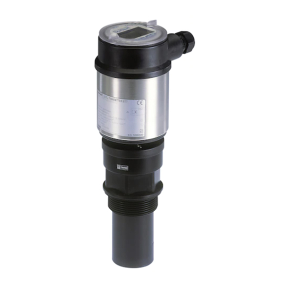
    Ultraschallsensor LEVEL TRANSMITTER 8177 Dokumentation Dieser Betriebsanleitung Betriebsanleitung "Anzeige- und Bedienmodul" (optional) Ggf. weiteren Bescheinigungen Der LEVEL TRANSMITTER 8177 besteht aus den Komponenten: Komponenten Schallwandler mit integriertem Temperaturfühler Gehäuse mit Elektronik Gehäusedeckel, optional mit Anzeige- und Bedienmodul Die Komponenten stehen in unterschiedlichen Ausführungen zur Verfügung.
  • Seite 100: Bedienung

    Mit dem Anzeige- und Bedienmodul Mit einem HART-Handbediengerät Die eingegebenen Parameter werden generell im LEVEL TRANS- MITTER 8177 gespeichert, optional auch im Anzeige- und Bedien- modul. 3.4 Verpackung, Transport und Lagerung Verpackung Ihr Gerät wurde auf dem Weg zum Einsatzort durch eine Verpackung geschützt.
  • Seite 101 Keinen aggressiven Medien aussetzen Vor Sonneneinstrahlung schützen Mechanische Erschütterungen vermeiden Lager- und Transport- Lager- und Transporttemperatur siehe Kapitel "Anhang - Techni- temperatur sche Daten - Umgebungsbedingungen" Relative Luftfeuchte 20 … 85 % LEVEL TRANSMITTER 8177 • 4 … 20 mA/HART...
  • Seite 102: Montieren

    Beachten Sie, dass unterhalb der Bezugsebene ein Mindestabstand - der sogenannte Totbereich - eingehalten werden muss, in dem keine Messung möglich ist. Den genauen Wert des Totbereichs finden Sie im Kapitel "Technische Daten". LEVEL TRANSMITTER 8177 • 4 … 20 mA/HART...
  • Seite 103 Wenn das Füllgut bis an den Schallwandler gelangt, können sich langfristig Anhaftungen am Schallwandler bilden, die später zu Fehlmessungen führen können. 100% Abb. 4: Messbereich (Arbeitsbereich) und maximale Messdistanz voll leer (maximale Messdistanz) Messbereich LEVEL TRANSMITTER 8177 • 4 … 20 mA/HART...
  • Seite 104: Montagehinweise

    Das Gehäuse darf nicht zum Einschrauben verwendet werden! Das Festziehen kann Schäden an der Drehmechanik des Gehäuses verursachen. Montieren Sie den LEVEL TRANSMITTER 8177 an einer Position, die Montageposition mindestens 200 mm (7.874 in) von der Behälterwand entfernt ist. Wenn der Sensor in Behältern mit Klöpper- oder Runddecken mittig montiert wird, können Vielfachechos entstehen, die durch einen...
  • Seite 105 Sensor in Behältermitte zu montieren, da die Messung dann bis zum Boden möglich ist. Abb. 6: Behälter mit konischem Boden Stutzen Bevorzugt sollte der Rohrstutzen so dimensioniert werden, dass die Unterseite des Schallwandlers mindestens 10 mm (0.394 in) aus dem Stutzen herausragt. LEVEL TRANSMITTER 8177 • 4 … 20 mA/HART...
  • Seite 106 4 Montieren Abb. 7: Empfehlenswerte Rohrstutzenmontage Bei guten Reflexionseigenschaften des Füllguts können Sie den LEVEL TRANSMITTER 8177 auch auf Rohrstutzen montieren, die höher als die Schallwandlerlänge sind. Richtwerte der Stutzenhöhen finden Sie in der nachfolgenden Abbildung. Das Stutzenende sollte in diesem Fall glatt und gratfrei, wenn möglich sogar abgerundet sein.
  • Seite 107 Abb. 9: Ausrichtung in Flüssigkeiten Um den Mindestabstand zum Füllgut zu verringern, können Sie den LEVEL TRANSMITTER 8177 auch mit einem Umlenkspiegel montie- ren. Dadurch können Sie Ihren Behälter fast vollständig befüllen. Diese Anordnung eignet sich in erster Linie für offene Behälter wie z. B.
  • Seite 108 Störreflektionen des Rührwerks in unterschiedlichen Positionen ab- gespeichert werden. Abb. 12: Rührwerke Einströmendes Füllgut Montieren Sie die Geräte nicht über oder in den Befüllstrom. Stellen Sie sicher, dass Sie die Füllgutoberfläche erfassen und nicht das einströmende Füllgut. LEVEL TRANSMITTER 8177 • 4 … 20 mA/HART...
  • Seite 109 Wenn starke Luftströmungen im Behälter auftreten, z. B. bei Montage im Freien und starkem Wind oder durch Luftturbulenzen im Behälter, z. B. durch Zyklonabsaugung, sollten Sie den LEVEL TRANSMITTER 8177 in einem Standrohr montieren oder ein anderes Messprinzip verwenden, z. B. Radar oder geführtes Radar (TDR). Standrohrmessung Durch den Einsatz in einem Standrohr (Schwall- oder Bypassrohr) sind Einflüsse von Behältereinbauten, Schaumbildung und Turbulenzen...
  • Seite 110 Abb. 14: Standrohr im Tank Entlüftungsbohrung ø 5 … 10 mm Der LEVEL TRANSMITTER 8177 ist ab Rohrdurchmessern von 40 mm einsetzbar. Vermeiden Sie große Spalte und starke Schweißnähte beim Ver- binden der Rohre. Führen Sie generell eine Störsignalspeicherung durch.
  • Seite 111: An Die Spannungsversorgung Anschließen

    Wenn geschirmtes Kabel notwendig ist, legen Sie den Kabelschirm beidseitig auf Erdpotenzial. Im Sensor muss der Schirm direkt an die dung innere Erdungsklemme angeschlossen werden. Die äußere Erdungs- klemme am Gehäuse muss niederimpedant mit dem Potenzialaus- gleich verbunden sein. LEVEL TRANSMITTER 8177 • 4 … 20 mA/HART...
  • Seite 112: Anschlussschritte

    Ziehen prüfen 10 Schirm an die innere Erdungsklemme anschließen, die äußere Erdungsklemme mit dem Potenzialausgleich verbinden 11 Überwurfmutter der Kabelverschraubung fest anziehen. Der Dichtring muss das Kabel komplett umschließen 12 Gehäusedeckel verschrauben LEVEL TRANSMITTER 8177 • 4 … 20 mA/HART...
  • Seite 113: Anschlussplan Einkammergehäuse

    Elektronik- und An- schlussraum Display I ² C 5 6 7 8 Abb. 16: Elektronik- und Anschlussraum Einkammergehäuse Serviceschnittstelle Federkraftklemmen zum Anschluss einer externen Anzeige Erdungsklemme zum Anschluss des Kabelschirms Federkraftklemmen für die Spannungsversorgung LEVEL TRANSMITTER 8177 • 4 … 20 mA/HART...
  • Seite 114: Einschaltphase

    Display I 2 C Abb. 17: Anschlussplan Einkammergehäuse Spannungsversorgung/Signalausgang 5.4 Einschaltphase Nach dem Anschluss des LEVEL TRANSMITTER 8177 an die Einschaltphase Spannungsversorgung bzw. nach Spannungswiederkehr führt das Gerät zunächst ca. 30 Sekunden lang einen Selbsttest durch: Interne Prüfung der Elektronik Anzeige des Gerätetyps, der Firmwareversion sowie des Sensor-...
  • Seite 115: In Betrieb Nehmen Mit Dem Anzeige- Und Bedienmodul

    Anzeige- und Bedienmodul auf die Elektronik setzen und leicht nach rechts bis zum Einrasten drehen Gehäusedeckel mit Sichtfenster fest verschrauben Der Ausbau erfolgt sinngemäß umgekehrt. Das Anzeige- und Bedienmodul wird vom Sensor versorgt, ein weiterer Anschluss ist nicht erforderlich. LEVEL TRANSMITTER 8177 • 4 … 20 mA/HART...
  • Seite 116 6 In Betrieb nehmen mit dem Anzeige- und Bedienmodul Abb. 18: Einbau des Anzeige- und Bedienmoduls Hinweis: Falls Sie das Gerät mit einem Anzeige- und Bedienmodul zur ständigen Messwertanzeige nachrüsten wollen, ist ein erhöhter Deckel mit Sichtfenster erforderlich. LEVEL TRANSMITTER 8177 • 4 … 20 mA/HART...
  • Seite 117: Bediensystem

    Die Funktionen der einzelnen Tasten entnehmen Sie bitte der vorhergehenden Darstellung. Ca. 10 Minuten nach der letzten Tastenbetätigung wird ein automatischer Rücksprung in die Messwertanzeige ausgelöst. Dabei gehen die noch nicht mit [OK] bestätigten Werte verloren. LEVEL TRANSMITTER 8177 • 4 … 20 mA/HART...
  • Seite 118: Inbetriebnahmeschritte

    Betriebsanleitung "Anzeige- und Bedienmodul". HART-Betriebsart Standard Adresse 0 Da es sich beim LEVEL TRANSMITTER 8177 um ein Distanzmess- Parametrierung gerät handelt, wird die Entfernung vom Sensor bis zur Füllgutober- fläche gemessen. Um die eigentliche Füllguthöhe anzeigen zu können, muss eine Zuweisung der gemessenen Distanz zur prozentualen Höhe erfolgen.
  • Seite 119 Passend zum Prozentwert den passenden Distanzwert in Meter für den vollen Behälter eingeben. Beachten Sie dabei, dass der maximale Füllstand unterhalb des Totbereiches liegen muss. Speichern der Einstellungen mit [OK] und wechseln mit [->] zur Mediumauswahl. LEVEL TRANSMITTER 8177 • 4 … 20 mA/HART...
  • Seite 120 Beachten Sie bitte, dass damit aber auch die Reaktionszeit der gesamten Messung länger wird und der Sensor auf schnelle Messwertveränderungen nur noch verzögert reagiert. In der Regel genügt eine Zeit von wenigen Sekunden, um die Messwertanzeige weit gehend zu beruhigen. LEVEL TRANSMITTER 8177 • 4 … 20 mA/HART...
  • Seite 121 Anlagen sollte zur genaueren Identifizierung der einzelnen Messstellen eine einmalige Bezeichnung eingegeben werden. Sensor-TAG Sensor Mit diesem Menüpunkt ist die Grundeinstellung abgeschlossen und Sie können nun mit der [ESC]-Taste ins Hauptmenü zurückspringen. LEVEL TRANSMITTER 8177 • 4 … 20 mA/HART...
  • Seite 122 Bedienmodul. Eine Beschreibung der Funktion finden Sie in der Betriebsanleitung "Anzeige- und Bedienmodul". Folgende Daten werden mit dieser Funktion ausgelesen bzw. ge- schrieben: Messwertdarstellung Abgleich Medium Behälterform Dämpfung Linearisierungskurve Sensor-TAG Anzeigewert Anzeigeeinheit Skalierung Stromausgang LEVEL TRANSMITTER 8177 • 4 … 20 mA/HART...
  • Seite 123 Die Werte folgender Menüpunkte werden mit dem "Reset" nicht auf die Resetwerte (siehe Tabelle) zurückgesetzt: Funktion Resetwert Beleuchtung kein Reset Sprache kein Reset HART-Betriebsart kein Reset Sensorspezifische Grundeinstellung. Je nach Sensortyp, siehe Kapitel "Technische Daten". LEVEL TRANSMITTER 8177 • 4 … 20 mA/HART...
  • Seite 124 Anzeigeskalierung, Simulation oder Trendkurvendarstellung sind im nachfolgenden Menüplan abgebildet. Eine nähere Beschreibung dieser Menüpunkte finden Sie in der Betriebsanleitung "Anzeige- und Bedienmodul". Spezialparameter sind Parameter, die mit der Bediensoftware PACTware auf der Serviceebene kundenspezifisch eingestellt werden. LEVEL TRANSMITTER 8177 • 4 … 20 mA/HART...
  • Seite 125: Menüplan Ultraschallsensor

    Diagnose Grundeinstellung Display ▶ Diagnose Service Info Schleppzeiger Messsicherheit Kurvenauswahl Echokurve Distanz min.: 0.234 m(d) 36 dB Distanz max.: 5.385 m(d) Gerätestatus Echokurve Darstellung der Echokurve T-min.: 16.5 °C T-min.: 37.5 °C LEVEL TRANSMITTER 8177 • 4 … 20 mA/HART...
  • Seite 126 Sensordaten kopieren? Jetzt aktivieren? Adresse 0 Info Grundeinstellung Display Diagnose Service ▶ Info Gerätetyp Kalibrierdatum letzte Änderung über PC Sensormerkmale 10. Januar 2008 Softwareversion Jetzt anzeigen? 3.50 10. Januar 2008 Seriennummer 12345678 LEVEL TRANSMITTER 8177 • 4 … 20 mA/HART...
  • Seite 127: Sicherung Der Parametrierdaten

    Betriebsanleitung, und anschließend zu archivieren. Sie stehen damit für mehrfache Nutzung bzw. für Servicezwecke zur Verfügung. Ist der LEVEL TRANSMITTER 8177 mit einem Anzeige- und Bedienmodul ausgestattet, so können die wichtigsten Daten aus dem Sensor in das Anzeige- und Bedienmodul gelesen werden. Die Vorgehensweise wird in der Betriebsanleitung "Anzeige- und Bedien-...
  • Seite 128: Instandhalten Und Störungen Beseitigen

    à Prüfen, ggf. anpassen Stromsignal größer 22 mA oder kleiner 3,6 mA Elektronikeinsatz defekt à Gerät austauschen bzw. zur Reparatur einsenden Bei Ex-Anwendungen sind die Regeln für die Zusammenschaltung von eigensicheren Stromkreisen zu beachten. LEVEL TRANSMITTER 8177 • 4 … 20 mA/HART...
  • Seite 129 Hardwarefehler, Elektronik defekt à Gerät austauschen bzw. zur Reparatur einsenden Verhalten nach Stö- Je nach Störungsursache und getroffenen Maßnahmen sind ggf. die rungsbeseitigung im Kapitel "In Betrieb nehmen" beschriebenen Handlungsschritte erneut zu durchlaufen. LEVEL TRANSMITTER 8177 • 4 … 20 mA/HART...
  • Seite 130: Ausbauen

    Mensch und Umwelt und ermöglicht eine Wiederverwendung von wertvollen Rohstoffen. Werkstoffe: siehe Kapitel "Technische Daten" Sollten Sie keine Möglichkeit haben, das Altgerät fachgerecht zu entsorgen, so sprechen Sie mit uns über Rücknahme und Entsorgung. LEVEL TRANSMITTER 8177 • 4 … 20 mA/HART...
  • Seite 131: Anhang

    Dämpfung (63 % der Eingangsgröße) NE 43 Erfüllte NAMUR-Empfehlung Eingangsgröße Messgröße Abstand zwischen Schallwandlerunterkante und Füllgutoberfläche Messbereich bis 8 m (26.25 ft) Flüssigkeiten bis 3,5 m (11.48 ft) Schüttgüter 0,4 m (1.312 ft) Totbereich LEVEL TRANSMITTER 8177 • 4 … 20 mA/HART...
  • Seite 132 -20 … 200 kPa/-0,2 … 2 bar (-2.9 … 29 psig) Prozessdruck Bezogen auf den Nennmessbereich, inkl. Hysterese und Wiederholbarkeit, ermittelt nach der Grenzpunktmethode. Zeit bis zur richtigen Ausgabe (max. 10 % Abweichung) des Füllstandes bei einer sprunghaften Füllstandänderung. LEVEL TRANSMITTER 8177 • 4 … 20 mA/HART...
  • Seite 133 20 … 30 V DC EEx-ia-Gerät Zulässige Restwelligkeit < 100 Hz < 1 V 100 Hz … 10 kHz < 10 mV Bürde siehe Diagramm Geprüft nach den Richtlinien des Germanischen Lloyd, GL-Kennlinie 2. LEVEL TRANSMITTER 8177 • 4 … 20 mA/HART...
  • Seite 134 9 Anhang Ω 1000 Abb. 21: Spannungsdiagramm HART-Bürde Spannungsgrenze EEx-ia-Gerät Spannungsgrenze Nicht-Ex-Gerät Betriebsspannung Elektrische Schutzmaßnahmen IP 66/IP 67 Schutzart Überspannungskategorie Schutzklasse LEVEL TRANSMITTER 8177 • 4 … 20 mA/HART...
  • Seite 135 2"NPT ø 50mm ") ø 74mm ") Abb. 23: LEVEL TRANSMITTER 8177 Totbereich: 0,4 m (1.312 ft) Messbereich: bei Flüssigkeiten bis 8 m (26.25 ft), bei Schüttgütern bis 3,5 m (11.48 ft) LEVEL TRANSMITTER 8177 • 4 … 20 mA/HART...
  • Seite 136 9 Anhang LEVEL TRANSMITTER 8177 • 4 … 20 mA/HART...
  • Seite 137 9 Anhang LEVEL TRANSMITTER 8177 • 4 … 20 mA/HART...
  • Seite 138 9 Anhang LEVEL TRANSMITTER 8177 • 4 … 20 mA/HART...
  • Seite 139 9 Anhang LEVEL TRANSMITTER 8177 • 4 … 20 mA/HART...
  • Seite 140 The smart choice of Fluid Control Systems www.buerkert.com Technische Änderungen vorbehalten 32059-DE-081114...

Inhaltsverzeichnis