bürkert 2002 Umbauanleitung
Umbau der steuerfunktion
Vorschau ausblenden
Andere Handbücher für 2002:
- Serviceanleitung (41 Seiten) ,
- Umbauanleitung (117 Seiten) ,
- Bedienungsanleitung (94 Seiten)

Verwandte Anleitungen für bürkert 2002


Inhaltszusammenfassung für bürkert 2002
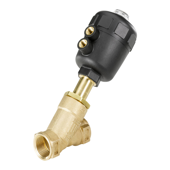
- Seite 1 Type 2000/2002/2012 Conversion of Control Function Umbau der Steuerfunktion Conversion Instructions Umbauanleitung...
- Seite 19 Anleitung für den Umbau der Steuerfunktionen von Ventilen des Typs 2000 / 2002 / 2012 Inhalt: 1. DIese anleItung ........................20 1.1. Darstellungsmittel .....................20 2. allgemeIne sIcherheItshInweIse ................ 21 3. teIlebezeIchnung ......................22 4. umbau Der steuerfunktIon ..................24 4.1. Änderung der Steuerfunktion A (Feder schließend) auf Steuerfunktion B (Feder öffnend) .................24 4.2. Änderung der Steuerfunktion A (Feder schließend) auf Steuerfunktion I (doppelt wirkender Antrieb) .............27...
-
Seite 20: Diese Anleitung
DIese anleItung Die Umbauanleitung beschreibt die Vorgehensweise für den Umbau der Steuerfunktion von Prozessventilen des Typs 2000, 2002 und 2012. Bewahren Sie diese Anleitung so auf, dass sie für jeden Benutzer gut zu- gänglich ist und jedem neuen Eigentümer des Gerätes wieder zur Verfügung steht. VorsIcht! Die Anleitung muss vor dem Beginn der Umbauarbeiten gelesen und verstanden werden. Lesen Sie deshalb die Umbauanleitung sorgfältig durch. Beachten Sie vor allem das Kapitel Allgemeine Sicherheits- hinweise 1.1. Darstellungsmittel In dieser Betriebsanleitung werden folgende Darstellungsmittel verwendet: markiert einen Arbeitsschritt, den Sie ausführen müssen. gefahr! bezeichnet eine unmittelbar drohende Gefahr. Wenn sie nicht gemieden wird, sind schwerste Verlet- zungen oder Tod die Folge. warnung! bezeichnet eine möglicherweise gefährliche Situation. Wenn sie nicht gemieden wird, können Tod oder schwerste Verletzungen die Folge sein. VorsIcht! bezeichnet eine möglicherweise gefährliche Situation. -
Seite 21: Allgemeine Sicherheitshinweise
• Gefahr durch hohen Druck! Bei Eingriffen in die Anlage besteht akute Verletzungsge- fahr. Schalten Sie den Druck ab, bevor Sie Leitungen und Ventile lösen!. • Gefahr durch elektrische Spannung! Bei Eingriffen in die Anlage besteht akute Verletzungsge- fahr. Schalten Sie vor Beginn der Arbeiten in jedem Fall die Spannung ab! Beachten Sie die geltenden Unfallverhütungs- und Sicherheitsbestimmungen für elektrische Geräte. warnung! • Unbeabsichtigtes Betätigen oder unzulässige Beeinträch- tigung können zu allgemeinen Gefahrensituationen bis hin zur Körperverletzung führen. Treffen Sie geeignete Maß- nahmen, um unbeabsichtigtes Betätigen oder unzulässige Beeinträchtigung auszuschließen! • Bei Installations- und Umbau- und Reparaturarbeiten können Gefahrensituationen entstehen. Diese Arbeiten dürfen nur durch autorisiertes Fachperso- nal und mit geeignetem Werkzeug durchgeführt werden! Verwenden Sie nur Originalersatzteile. • Gewährleisten Sie nach einer Unterbrechung der elektri- schen oder pneumatischen Versorgung einen definierten und kontrollierten Wiederanlauf des Prozesses! VorsIcht! Für den Umbau der Prozessventile gelten die allgemeinen Regeln der Technik! Beachten Sie die Regeln nicht, kön- nen Verletzungen entstehen und/oder das Gerät, ggf. auch dessen Umgebung, können beschädigt werden. Halten Sie die allgemeinen Regeln der Technik ein! 2000/2002/2012 - 21... -
Seite 22: Teilebezeichnung
Steuerfunktion A (SFA) Steuerfunktion B (SFB) 22 - 2000/2002/2012... - Seite 23 Detailzeichnung: Stopfbuchsensatz pos. bezeichnung Ventilgehäuse Spindel Pendelteller Dichtring Nippel Abstreifer (zu Stopfbuchsensatz) Rohr Verstärkungsring O-Ring Laufbuchse Stopfbuchsensatz einschließlich Pos. 7 und Pos. 39 Tellerfeder Schraube Füllkörper Zwischenscheibe O-Ring Kolben Kolbendichtung Stützscheibe Ventilgehäuse Typ 2012 Mutter Stellungsanzeige Druckfeder Druckfeder O-Ring Deckel O-Ring Druckfeder Stopfbuchsensatz Scheibe 2000/2002/2012 - 23...
-
Seite 24: Umbau Der Steuerfunktion
Der steuerfunktIon 4.1. änderung der steuerfunktion a (feder schließend) auf steuerfunktion b (feder öffnend) 4.1.1. montage Benötigte Teile: 1 Druckfeder (Pos. 35) 1 O-Ring (Pos. 30) 1 Graphit-Dichtung (Pos. 5) Ventilgehäuse Typ 2000 / 2002 Ventilgehäuse Typ 2012 Abb.: Darstellung der Steuerfunktionen SFA und SFB 24 - 2000/2002/2012... - Seite 25 • Mutter (Pos. 25) lösen. • Kolben (Pos. 22) mit Stützscheibe (Pos. 24) entnehmen. • Füllkörper (Pos. 19) mit Zwischenscheibe (Pos. 20) und O-Ring (Pos. 21) entnehmen (der Füllkörper wird für SFB nicht benötigt). • Neue Druckfeder SFB (Pos. 35) einsetzen. • Scheibe (Pos. 20) und O-Ring (Pos. 21) auf Spindelansatz aufstecken. • Kolben (Pos. 22) auf Spindel (Pos. 2) stecken. • Stützscheibe (Pos. 24) aufstecken. ® • Spindelgewinde mit Flüssigkleber "LOCTITE 274" benetzen. • Mutter (Pos. 25) auf Spindel schrauben. • Stellungsanzeige montieren. • Neuen O-Ring (Pos. 30) in Nut der Laufbuchse einlegen. • Dichtring (Pos. 5) prüfen und evtl. auswechseln. • bei Va-gehäuse: Nippelgewinde (Pos. 6) mit "Klüberpaste UH1 96-402" einfetten. • Gehäuse (Pos. 1) einspannen. • Nippel (Pos. 6) samt Antrieb in Gehäuse (Pos. 1) schrauben. VorsIcht! Beachten Sie das Drehmoment beim Einschrauben des Antriebes in das Gehäuse (siehe Tabelle). 2000/2002/2012 - 25...
- Seite 26 • nur bei antriebsgröße g-100 und h-125: Scheibe (Pos. 40) einlegen. • Deckel (Pos. 31) mit Spezialschlüssel verschrauben. • Ventil auf Funktion und Dichtheit prüfen. Tabelle: Umbausätze antrieb Ø [mm] best.-nr. C-40 229 900 D-50 012 090 E-63 011 946 F-80 011 955 G-100 011 957 H-125 011 964 Tabelle: Drehmomente werkstoff Drehmoment nippelge- (Richtwerte) [Nm] winde messing oder edelstahl 26 - 2000/2002/2012...
-
Seite 27: Änderung Der Steuerfunktion A (Feder Schließend) Auf Steuerfunktion I (Doppelt Wirkender Antrieb)
4.2. änderung der steuerfunktion a (feder schließend) auf steuerfunktion I (doppelt wirkender antrieb) Bei SFI (doppelt wirkender Antrieb) wird der Kolben ohne Federgegenkraft über beide Steueranschlüsse betätigt. Bei Steuerdruck auf den unteren Steueranschluss wird das Ventil geöffnet; bei Steuerdruck auf den oberen Steueranschluss geschlossen. Der Umbau beschränkt sich auf die Entnah- me im Antrieb vorhandener Druckfedern und den Einbau eines O-Ringes. 4.2.1. montage Benötigte Teile: 1 O-Ring (Pos. 30) Ventilgehäuse Typ 2000 / 2002 Ventilgehäuse Typ 2012 Abb.: Darstellung der Steuerfunktionen SFA und SFI 2000/2002/2012 - 27... - Seite 28 • Deckel (Pos. 31) mit Spezialschlüssel abschrauben, am Sechskant der Laufbuchse (Pos. 12) gegenhalten. VorsIcht! Kolbenantrieb vorsichtig öffnen - Unfallgefahr durch ge- spannte Federn. • nur bei antriebsgröße g-100 / h-125 mm: Scheibe (Pos. 40) entnehmen. • Druckfedern (Pos. 28, 29) entnehmen. • O-Ring (Pos. 30) in Nut der Laufbuchse einlegen. • Deckel (Pos. 31) mit Spezialschlüssel verschrauben. • Ventil auf Funktion und Dichtheit prüfen. Tabelle: Umbausätze antrieb Ø [mm] best.-nr. C-40 auf Anfrage D-50 11 965 E-63 12 103 F-80 11 976 G-100 11 977 H-125 11 980 28 - 2000/2002/2012...
-
Seite 29: Umbau Von Anströmung Über Sitz Auf Anströmung Unter Sitz
• Druckfedern (Pos. 28, 29) je nach An- trieb entnehmen und / oder einsetzen. • antrieb c-40, D-50, e-63, f-80: Druckfedern entnehmen und neue, stär- kere Federn einsetzen. • antrieb g-100, h-125: neue äußere Feder (Pos. 29) zusätzlich zur vorhandenen inneren Feder (Pos. 28) einbauen. Ventil- • Deckel (Pos. 31) mit Spezialschlüssel gehäuse verschrauben. Typ 2000 und 2002 • Ventil auf Funktion und Dichtheit prüfen. VorsIcht! Beachten Sie die veränderte Ventil- Durchflussrichtung und den gehäuse veränderten Druckbereich! Typ 2012 2000/2002/2012 - 29... - Seite 30 Tabelle: Umbausätze antrieb Ø [mm] best.-nr. D-50 012 016 E-63* 012 023 F-80 012 029 F-80** 012 059 G-100 012 071 G-100** 012 082 H-125 012 086 H-125** 012 089 * PA + PPS-Antrieb ** PPS-Antrieb 30 - 2000/2002/2012...
-
Seite 31: Umbau Von Anströmung Unter Sitz In Anströmung Über Sitz
• Druckfedern (Pos. 28, 29) je nach An- trieb entnehmen und / oder einsetzen. • antrieb c-40, D-50, e-63, f-80: Druckfedern entnehmen und neue, schwächere Federn einsetzen. • antrieb g-100, h-125: Ventil- Nur äußere Feder (Pos. 29) entnehmen, gehäuse inneren Feder (Pos. 28) verbleibt im Typ 2000 Antrieb. und 2002 • Deckel (Pos. 31) mit Spezialschlüssel verschrauben. • Ventil auf Funktion und Dichtheit prüfen. Ventil- VorsIcht! gehäuse Typ 2012 Beachten Sie die veränderte Durchflussrichtung und den veränderten Druckbereich! 2000/2002/2012 - 31... -
Seite 32: Empfohlene Hilfsstoffe
F-80 012 005 F-80** 012 011 G-100 Nur Außenfeder ausbauen! H-125 * PA + PPS-Antrieb ** PPS-Antrieb empfohlene hIlfsstoffe 5.1. produktbezeichnungen und hersteller In dieser Anleitung werden für die einwandfreie Wartung und Reparatur des Gerätes, folgende Hilfsstoffe empfohlenen: art des produkt- hersteller und Internetadresse hilfsstoffs bezeichnung Schmierpaste Klüberpaste UH1 Klüber Lubrication München KG 96-402 www.klueber.de ® Flüssigkleber LOCTITE 274 Henkel Loctite Deutschland GmbH www.loctite.de 32 - 2000/2002/2012... -
Seite 33: Werkzeugsätze
6.1. montageschlüssel montageschlüssel für die antriebe c-40, D-50 Antrieb Ø [mm] Best. Nr. C-40 639 175 D-50 639 175 montageschlüssel für antrieb e-63 Ø [mm] Best. Nr. 639 170 montageschlüssel für die antriebegrößen f-80, g-100, h-125 Antrieb Ø [mm] Best. Nr. F-80 639 171 G-100 639 712 H-125 639 713 2000/2002/2012 - 33... -
Seite 34: Montagehülsen
639 166 montagehülse für spindel Ø 10 mm antriebsgröße Ø [mm] maß D [mm] best. nr. E-63 20, 25, 32, 40, 50 Ø 6 639 167 F-80 25, 32, 40, 50, 65 Ø 8 639 168 montagehülse für spindel Ø 16 mm antriebgröße Ø [mm] maß D [mm] best. nr. G-100 32, 40, 50, 65 639 169 H-125 32, 40, 50, 65 639 169 34 - 2000/2002/2012... - Seite 35 2000/2002/2012 - 35...
- Seite 36 36 - 2000/2002/2012...